Safety valve technical blog · RFQ parameter validation Flanged Safety Valve RFQ Guide: Parameters Buyers Must Confirm A flanged safety valve is a pressure-relieving valve connected to equipment or piping by bolted flanges at the inlet, outlet, or both. The flange defines the mechanical interface; it does not prove that the valve opens at the …

Safety valve technical blog · RFQ parameter validation
Flanged Safety Valve RFQ Guide: Parameters Buyers Must Confirm
A flanged safety valve is a pressure-relieving valve connected to equipment or piping by bolted flanges at the inlet, outlet, or both. The flange defines the mechanical interface; it does not prove that the valve opens at the required pressure, passes the required relieving load, remains stable under back pressure, uses compatible materials, or carries the documentation required by the project. A technically usable RFQ must identify the protected equipment and relief scenario, then state the medium and phase, operating and design pressures, set pressure, required capacity, relieving temperature, back pressure, inlet and outlet flange details, materials, valve configuration, tests, and records. Do not approve a valve only because its flange size matches the existing nozzle.
Connection
Specify inlet and outlet size, standard, class or PN, facing, gasket, and mating-pipe requirements.
Protection duty
Confirm the governing relief scenario, required relieving capacity, pressure basis, medium, and temperature.
Acceptance evidence
Define the capacity basis, code marking, tests, material records, inspection scope, and traceability before quotation.
What Must Be Confirmed Before Buying a Flanged Safety Valve?
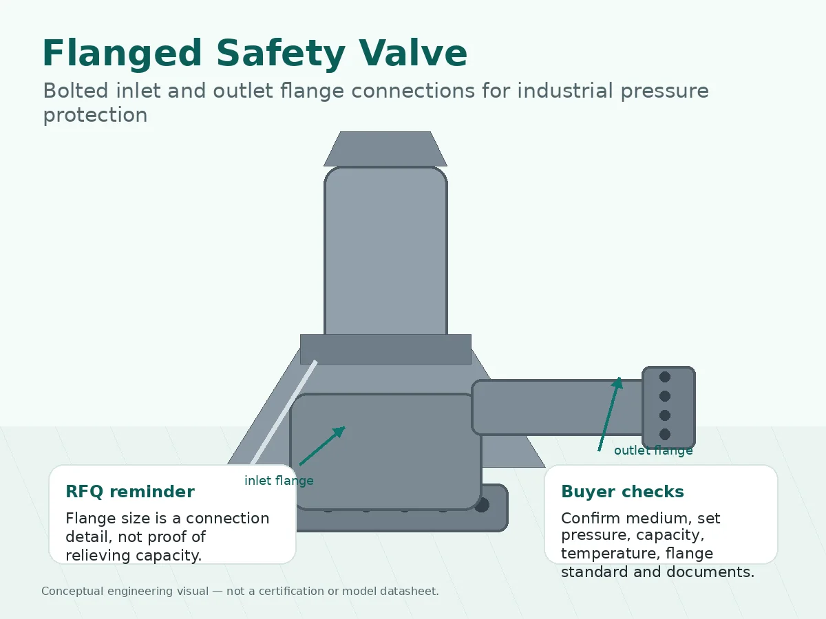
Confirm the protection duty before the connection. Begin with the protected equipment and credible overpressure case, then provide the medium and phase, operating pressure, MAWP or applicable design limit, set pressure, required relieving capacity, relieving pressure and temperature basis, back pressure, and installation arrangement. Only after that should the RFQ lock the inlet and outlet flange standard, nominal size, pressure class or PN, facing, material, gasket, bolting, valve type, seat, spring range, code marking, tests, and document package.
The flanged safety valves category can support product-family navigation, but a category page or model name is not a sizing calculation or approval record. For the capacity workflow, use the separate safety valve sizing and certified relieving capacity guide.
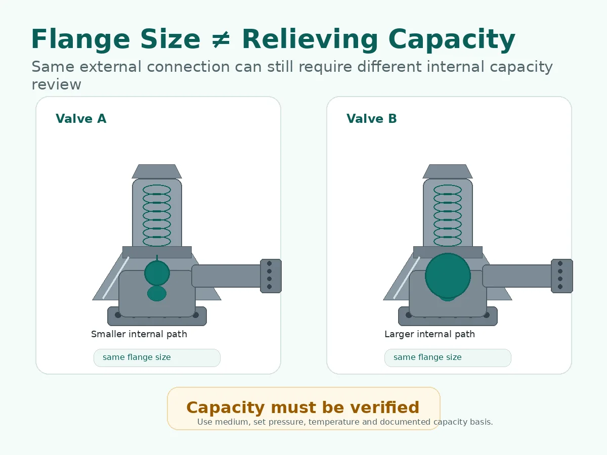
Decision boundary: same flange size, same pressure class, or the same set pressure does not establish equivalent relieving capacity. Steam, gas, liquid, and two-phase duties also require different capacity bases and cannot be interchanged by appearance.
What Is a Flanged Safety Valve?
A flanged safety valve is a pressure-relieving device whose inlet, outlet, or both use bolted flange connections. The flange provides a defined piping interface and pressure boundary. The safety function still depends on the internal nozzle or seat, disc, guide, spindle, spring or pilot system, lift characteristic, blowdown behavior, back-pressure response, materials, and documented capacity.
Terminology varies across industries and standards. “Safety valve,” “safety relief valve,” “pressure relief valve,” “pressure safety valve,” PSV, PRV, and SRV may overlap in commercial usage, but the product name alone is not a complete technical definition. In some contexts PRV also means pressure-reducing valve, which is a different device. The RFQ should therefore identify the opening characteristic, service fluid and phase, valve configuration, capacity basis, code marking, and applicable project definition. ZOBAI’s pressure relief valves page provides broader product terminology, while this article retains RFQ ownership for flanged connection and buyer-data validation.
What the flange connection confirms
The flange data can confirm nominal size, dimensional standard, rating system, facing, gasket interface, bolt pattern, and compatibility with the equipment nozzle or piping. A complete statement may identify an ASME, EN, DIN, JIS, GB, or project-specific standard; the inlet and outlet often require separate entries.
What the flange connection cannot confirm
The flange does not prove required or certified relieving capacity, correct set pressure, acceptable operating margin, stable operation under back pressure, suitable materials, seat tightness, or code compliance. A Class or PN designation is a pressure-temperature rating reference for the connection and material system; it is not the valve set pressure or the protected equipment MAWP.
Where Are Flanged Safety Valves Commonly Specified?
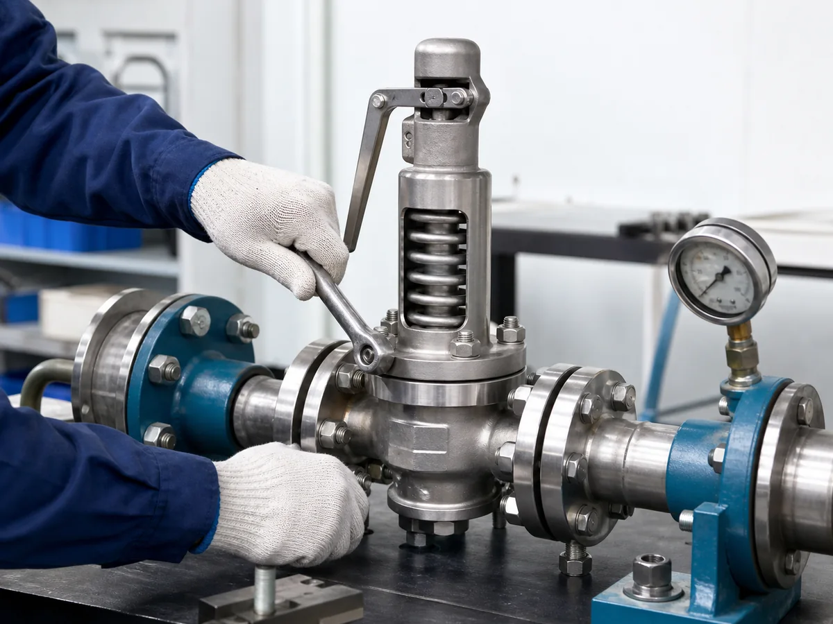
Flanged safety valves are commonly specified on pressure vessels, boilers, steam headers, compressors, process skids, reactors, heat exchangers, gas systems, chemical lines, and installations connected to vent or relief headers. These applications often use bolted plant piping, require repeatable removal for inspection, or need an outlet connection that can carry discharge piping.
The application name is only context. “Boiler valve,” “vessel PSV,” or “steam safety valve” does not identify the governing relief scenario or required load. A fire case, blocked outlet, regulator failure, tube rupture, thermal expansion, runaway reaction, and utility failure can produce different relieving conditions and may require different device and system reviews.
Protected equipment
Identify the vessel, boiler, compressor, exchanger, pipeline, skid, or other pressure system and the limit that must be protected.
Governing scenario
State the credible overpressure case and required relieving load rather than assuming the line or nozzle size defines the valve.
Installed system
Show inlet piping, outlet routing, headers, drains, supports, isolation arrangements, and maintenance access.
Use the broader safety valve selection guide when the main question is valve type or service suitability rather than flanged RFQ data.
When Is “Flanged Safety Valve” an Incomplete Specification?
“Flanged” is complete only as a connection-form statement. The table separates useful buyer information from statements that still leave a material engineering gap.
| Buyer statement | What it confirms | What remains unknown | Required action |
|---|---|---|---|
| “We need a flanged safety valve.” | The intended connection form. | Protected equipment, relief case, pressure basis, capacity, medium, temperature, flange details, materials, tests, and documents. | Request the full RFQ data set before model selection. |
| “The inlet is DN80 PN40.” | One nominal inlet size and rating designation. | Flange standard, facing, material group, temperature, outlet connection, set pressure, capacity, and piping loads. | Define both flange ends and verify the pressure-temperature basis. |
| “The replacement has the same face-to-face and flange size.” | Potential dimensional fit. | Orifice, certified capacity, spring range, trim, code marking, back-pressure response, and service history. | Compare nameplates, datasheets, certified data, and installed conditions. |
| “The valve passed its set-pressure test.” | The tested opening-pressure setting under the stated test condition. | Capacity, seat-tightness acceptance, stable lift, material condition, and installed-system suitability. | Do not treat a set-pressure test as a capacity or installation review. |
| “The outlet connects to a common header.” | Back pressure and discharge-system interaction are relevant. | Superimposed and built-up pressure, variability, simultaneous cases, drainage, support, and bonnet-vent routing. | Review the outlet system and the need for conventional, balanced-bellows, or pilot-operated configuration. |
Flanged Safety Valve RFQ Parameters Buyers Should Confirm
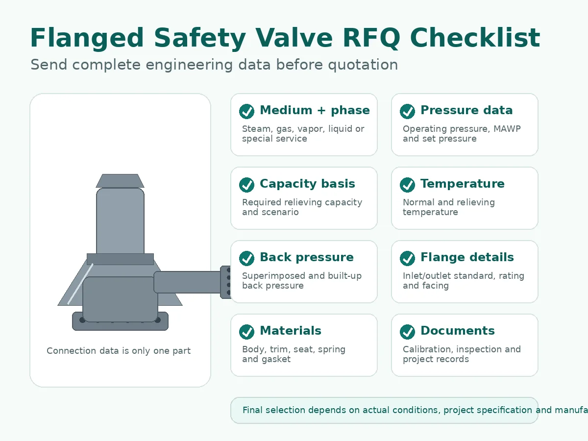
A quotation can only be technically meaningful when the supplier can trace the requested valve back to a defined protection duty. Mark unknown data as unknown; do not replace missing values with assumptions.
| RFQ parameter | Engineering effect | What to provide | Common misuse |
|---|---|---|---|
| Protected equipment and governing relief scenario | Defines what limit is protected and the load the valve must handle. | Equipment type, MAWP or applicable limit, P&ID or datasheet, and governing scenario or calculation basis. | Selecting from line size without identifying the relief case. |
| Medium, composition, and phase | Controls sizing method, coefficient basis, materials, seat, fouling risk, and discharge handling. | Steam, gas, vapor, liquid, flashing or two-phase condition; composition, density or other properties where required. | Using a gas capacity for liquid or two-phase duty. |
| Operating pressure and operating margin | Affects leakage, simmer, cycling, and stability below set pressure. | Normal and maximum expected operating pressure, including cycling or pressure pulsation. | Applying one fixed percentage to every valve type, medium, and code. |
| MAWP or applicable equipment design limit | Provides the protected-equipment pressure basis. | The value and governing construction code or project rule. | Substituting flange class or line design pressure for equipment MAWP without review. |
| Set pressure and CDTP where applicable | Set pressure defines the adjusted opening point; cold differential test pressure may account for specified service effects during shop setting. | Required set pressure, units, service temperature, back pressure, and project requirement for CDTP. | Treating set pressure or shop test pressure as proof of capacity. |
| Overpressure, accumulation, and relieving pressure basis | These values affect the relieving condition and capacity calculation but are not interchangeable terms. | Project-approved allowance and the resulting relieving pressure basis. | Applying a generic allowance without checking the equipment code, scenario, device type, and jurisdiction. |
| Required relieving capacity | Defines the minimum flow the selected valve must pass for the governing scenario. | Mass or volumetric flow, units, fluid basis, relieving conditions, and calculation reference. | Replacing required capacity with connection size or nominal valve size. |
| Relieving temperature | Affects fluid properties, flange rating, body and trim material, spring environment, gasket, and seat. | Normal, relieving, and relevant ambient or fire-exposure temperature data. | Checking material at normal temperature only. |
| Back pressure | Can change opening behavior, lift, stability, blowdown, capacity, and configuration suitability. | Superimposed and built-up values, constant or variable behavior, and header operating range. | Stating only “piped discharge” without pressure data or layout. |
| Inlet and outlet piping | Inlet pressure loss and outlet resistance can create instability or reduce performance; piping also transfers mechanical loads. | Line sizes, lengths, fittings, reducers, valves, elevation, drainage, support, and discharge destination. | Assuming the valve can correct a poor piping layout. |
| Inlet and outlet flange details | Determines dimensional fit, pressure-temperature suitability, gasket interface, and bolting arrangement. | Separate size, standard, class or PN, facing, material, gasket, and any project drilling or finish requirement. | Sending only DN or NPS. |
| Valve configuration and opening characteristic | Conventional, balanced-bellows, and pilot-operated designs respond differently to back pressure and contamination; pop, proportional, full-lift, and low-lift descriptions also require model-specific confirmation. | Required type or the conditions needed for the supplier to recommend one, plus service cleanliness and maintenance constraints. | Selecting a configuration from its commercial name alone. |
| Materials and seat | Body, bonnet, nozzle, disc, guide, spindle, spring, bellows, gasket, packing, soft seat, and O-ring may face different damage mechanisms. | Material specification, corrosion data, temperature, contaminants, sour-service requirement where applicable, and leakage acceptance. | Specifying only the body material. |
| Tests, marking, and documents | Determines project acceptance and traceability. | Required code marking, capacity evidence, set-pressure record, seat-tightness requirement, material records, inspection scope, nameplate, sealing, and document format. | Assuming every certificate or test is included with every model. |
The values above form an RFQ input set, not an approval by themselves. The responsible engineer must still confirm the governing code, relief calculation, selected model, manufacturer data, and installed-system design.
How Should Inlet and Outlet Flange Details Be Specified?
Treat each flange end as a separate line item. The inlet connects the device to the protected equipment or inlet piping; the outlet connects it to atmosphere, a vent stack, silencer, recovery line, scrubber, or common header. The two ends often have different sizes and ratings.
Inlet flange and inlet piping
State the nominal size, flange standard, class or PN, facing, material, gasket, and project-specific finish or drilling. Also review the inlet nozzle and piping because excessive loss, restrictions, pockets, poor alignment, or isolation-valve position can affect valve stability and the pressure seen at the inlet.
Outlet flange and discharge system
State the outlet flange data separately and identify the discharge destination. Outlet piping must be reviewed for resistance, built-up back pressure, reaction force, thermal expansion, support, drainage, liquid pockets, and safe routing. Heavy or misaligned piping should not load the valve body or flange joint.
Facing, gasket, bolting, and pressure-temperature rating
RF, FF, RTJ, and other facing arrangements are not interchangeable by label alone. The mating flange, gasket type, material, bolting, surface condition, assembly procedure, pressure, and temperature must be compatible. A nominal class or PN designation must be checked against the adopted flange standard, material group, and service temperature.
Replacement control: photographs help identify the connection, but the original datasheet, dimensional drawing, flange standard, material, nameplate, and piping specification remain the stronger evidence. Measure only after confirming that the existing installation itself was correct.
Why Flange Size Does Not Prove Relieving Capacity
Connection size answers “will it fit?” Relieving capacity answers “can it protect the equipment under the governing event?” These are different questions. Two valves with the same inlet and outlet flanges can use different effective orifice areas, actual bores, lift, internal geometry, coefficients, fluid bases, and certified or rated capacities.
Capacity terms that must remain separate
| Term | Engineering meaning | RFQ evidence | Do not confuse it with |
|---|---|---|---|
| Required relieving capacity | The load calculated for the governing overpressure scenario. | Calculation sheet or approved flow requirement with units and conditions. | Nominal connection size or catalog maximum. |
| Certified or rated relieving capacity | Documented device performance under defined test and rating conditions. | Applicable certified data, manufacturer rating data, code marking, and exact model/configuration identification. | Set-pressure calibration or seat-tightness test. |
| Effective orifice area | An area used in a defined sizing or standardization method. | Applicable standard designation and selected valve data. | Actual measured bore or flange bore. |
| Actual bore and internal geometry | Physical flow-path dimensions used by the specific design. | Manufacturer drawing and model-specific data where required. | A standardized effective area without checking the method. |
| Coefficient and fluid basis | The performance basis depends on the calculation method, test medium, phase, pressure, and temperature. | Applicable coefficient, fluid basis, and rating conditions. | Capacity for a different medium or phase. |
| Connection size | The physical interface to the inlet and outlet piping. | Flange size and standard. | Protection capacity. |
Composite engineering scenario: same flange, insufficient capacity
In a composite engineering scenario, a replacement valve matched the old 2 × 3 in flanges and set pressure, so it was initially treated as equivalent. Review of the selected model later showed a different internal orifice and a lower documented gas capacity than the governing relief load. The correction was to reopen the relief calculation, select a valve with adequate documented capacity, and then verify flange fit and discharge piping. The preventive control is to require capacity evidence and exact model configuration in every replacement comparison.
Where API-style flanged dimensions or effective-orifice designations are relevant, use the dedicated API 526 flanged safety valve guide; API 526 does not replace the relief calculation or the check between required and documented capacity.
What Back-Pressure and Piping Data Belong in the RFQ?
Back pressure is not one number unless the discharge system makes it one. Superimposed back pressure exists at the outlet before the valve opens; built-up back pressure develops from flow through the discharge system after opening. Either can be constant or variable. Their effect depends on valve design, pressure level, variability, discharge resistance, and the manufacturer’s documented limits.
| Condition | Possible consequence | Data to provide | Review implication |
|---|---|---|---|
| Superimposed back pressure | May shift opening or closing behavior and affect a conventional design. | Normal, minimum, and maximum outlet pressure before discharge; state whether constant or variable. | Check valve configuration and pressure-setting basis. |
| Built-up back pressure | May reduce lift or capacity and promote instability during flow. | Outlet hydraulic calculation, pipe size, length, fittings, silencer, header, and simultaneous cases. | Check outlet sizing and manufacturer limits. |
| Inlet pressure loss | Can decouple vessel pressure from valve-inlet pressure and contribute to cycling or chatter. | Inlet line geometry, fittings, branch connection, isolation arrangement, and calculated loss. | Review the installed system, not only the valve adjustment. |
| Liquid pockets or poor drainage | Can add static head, corrosion, freezing, water hammer, or discharge restriction. | Elevation, low points, drains, weather exposure, and fluid phase changes. | Correct routing and drainage before commissioning. |
| Discharge reaction and piping load | Can damage the valve, flange joint, support, or connected nozzle. | Support arrangement, flexibility, reaction calculation, alignment, and thermal movement. | Do not use the valve body as a pipe support. |
| Bellows bonnet vent or pilot sensing path | Incorrect routing, plugging, condensate, icing, or contamination can defeat the intended function. | Vent destination, sensing-line layout, cleanliness, heat tracing, and maintenance access. | Follow the selected manufacturer’s installation requirements. |
Composite engineering scenario: header modification and chatter
In a composite engineering scenario, a conventional spring-loaded valve began cycling after several outlets were connected to a common header. The valve had not changed; the discharge resistance and variable back pressure had. The correction combined a header hydraulic review, outlet-piping changes, and reassessment of whether a balanced-bellows or pilot-operated configuration was appropriate. The preventive control is management of change for every relief-header modification, with simultaneous discharge cases included where credible.
Chatter should not be assigned automatically to spring adjustment. Also check oversized selection, inlet pressure loss, insufficient sustainable flow, outlet resistance, mechanical loads, valve type, and process cycling. See the focused back pressure and bellows guide for the dedicated mechanism discussion.
Threaded vs Flanged Safety Valve: What Changes in the RFQ?
Both connection forms can be suitable when the valve is correctly sized, configured, installed, and documented. The comparison below is limited to procurement and installation interfaces; it does not assign capacity or compliance based on connection form.
| RFQ factor | Threaded safety valve | Flanged safety valve | Buyer control |
|---|---|---|---|
| Connection identification | Thread form, size, gender, sealing method, and engagement. | Inlet/outlet size, standard, class or PN, facing, gasket, and bolting. | Do not use nominal size without the connection standard. |
| Typical installation context | Often compact equipment or smaller piping, subject to actual service limits. | Often plant piping, equipment nozzles, larger valves, or piped discharge systems. | Use the installed system and maintenance method, not a generic size rule. |
| Mechanical installation risk | Thread damage, sealant contamination, orientation, and torsional load. | Misalignment, gasket selection, bolt loading, piping weight, and flange-face mismatch. | Specify the assembly method and support arrangement. |
| Replacement risk | NPT, BSPP, BSPT, G, Rc, or other thread mismatch. | Same size but different standard, class, facing, dimensions, material, or internal capacity. | Compare datasheets and nameplates, not appearance. |
| Protection performance | Requires the same relief-scenario, pressure, capacity, material, and installed-system review. | Requires the same relief-scenario, pressure, capacity, material, and installed-system review. | Connection form never replaces sizing or certification review. |
For the product-family comparison, review threaded safety valves. Keep “threaded vs flanged” comparison intent on the relevant comparison page rather than expanding this RFQ page into a full connection-selection article.
Which Procurement Mistakes Most Often Produce an Unusable Quote?
The highest-risk errors come from treating one visible parameter as a substitute for the complete pressure-protection basis.
Selecting by flange size and class only
“DN80 Class 300” does not state the relief scenario, medium, set pressure, required capacity, relieving temperature, back pressure, facing, material, or documentation. It can produce a dimensionally plausible quote that is technically unverified.
Confusing set pressure, overpressure, accumulation, and relieving pressure
These terms answer different questions. The RFQ should not use them as synonyms or apply a universal percentage. The adopted equipment code, scenario, valve type, jurisdiction, and project specification must define the permitted basis.
Using a set-pressure or seat-tightness test as capacity evidence
A set-pressure test checks the adjusted opening pressure under specified test conditions. A seat-tightness test evaluates leakage under its stated method. Neither establishes the required relieving load or proves certified capacity. The RFQ should identify each test purpose separately.
Ignoring the installed piping system
A correctly manufactured valve can still perform poorly with excessive inlet loss, high or variable outlet back pressure, liquid pockets, poor support, blocked vents, or heavy piping loads. Use the safety valve installation guide for installation-specific checks without transferring that page’s full maintenance intent into this RFQ guide.
Replacing by appearance without management of change
Review capacity, orifice, spring range, materials, seat, code marking, flange data, dimensions, back-pressure limits, discharge layout, and service history. If production rate, medium, relief scenario, equipment MAWP, header arrangement, or piping has changed, repeat the relevant sizing and system checks.
How Should Materials, Tests, and Documents Be Screened?
Material selection must follow the components exposed to pressure, process fluid, discharge fluid, temperature, corrosion, galling, deposits, and cyclic movement. Body material alone is not a complete material specification.
| Screening item | Engineering concern | RFQ input | Acceptance evidence |
|---|---|---|---|
| Body and bonnet | Pressure-temperature rating, external environment, corrosion, and construction. | Material grade, service temperature, environment, and project material specification. | Manufacturer datasheet, material record where required, and pressure-rating basis. |
| Nozzle, disc, guide, and spindle | Wetted corrosion, erosion, galling, sticking, wear, and seat damage. | Medium composition, contaminants, solids, corrosion mechanism, and required trim. | Exact component material list and model documentation. |
| Spring and bellows | Temperature stability, corrosion, fatigue, pressure balance, and vent environment. | Temperature, bonnet condition, back pressure, vent routing, and corrosion requirement. | Spring range, bellows material, configuration drawing, and manufacturer limits. |
| Gasket, packing, soft seat, and O-ring | Chemical compatibility, temperature, decompression, aging, leakage, and maintenance life. | Medium, pressure, temperature, cleaning chemicals, leakage criterion, and elastomer restrictions. | Material identification, model limit, and required conformity record. |
| Sour service where applicable | H₂S-related cracking and hardness/material-control requirements. | Explicit project adoption of NACE MR0175 / ISO 15156 or other governing sour-service requirement and the service data needed to apply it. | Component-level material, heat treatment, hardness, and project-required documentation. |
| Tests and traceability | Opening-pressure setting, seat tightness, pressure boundary, material identity, repair status, and records. | Required set-pressure test, seat-tightness method, shell test, witness points, as-found/as-left data, resealing, nameplate, and document format. | Test records and traceability matched to the exact valve serial or identification number. |
Composite engineering scenario: upgraded body, unchanged trim
In a composite engineering scenario, a stainless body was requested to address corrosion, but the RFQ did not define the nozzle, disc, guide, spindle, spring, gasket, or soft-seat materials. The valve body remained acceptable while the internal guide corroded and began to bind. The correction was a component-level material review based on the actual medium and temperature. The preventive control is to issue a complete bill-of-material requirements list or state the service conditions clearly enough for every affected component to be reviewed.
Repair and post-maintenance document boundary
For replacements or repaired valves, ask for as-found and as-left data where applicable, the set-pressure test basis, seat-tightness test, parts replaced, spring range, nameplate and seal status, and repair-organization authorization required by the jurisdiction or owner. A National Board VR authorization controls a repair quality-system route where applicable; it does not approve the original sizing, capacity, or installed-system design.
What Should Buyers Send for a Flanged Safety Valve Engineering Review?
Send the shortest data package that still allows the protection duty, valve configuration, connection, and acceptance evidence to be checked. Unknown values should be identified and resolved before final approval.
For a new project
Provide the equipment datasheet or description, P&ID, governing relief scenario, calculation or required capacity, medium and phase, composition or fluid properties where needed, operating pressure, MAWP or design basis, set pressure, overpressure and relieving-condition basis, temperature, back pressure, inlet and outlet piping layout, flange details, material requirements, applicable code, code marking, inspection plan, and document list.
For a replacement
Provide the existing nameplate, original datasheet, model and serial identification, certified or rated capacity evidence, inlet and outlet flange data, dimensional drawing, installation photographs, piping layout, calibration and seat-leakage records, maintenance findings, and any process or header changes since the original installation. Do not assume the old valve was correctly selected.
For a repaired or recalibrated valve
State the governing repair route and required records. Request as-found/as-left values where applicable, set-pressure and seat-tightness results, replaced parts, spring range, material traceability, resealing and nameplate control, and the repair organization’s applicable authorization. Keep repair quality-system evidence separate from sizing and installed-system acceptance.
FAQ About Flanged Safety Valve RFQs
What is a flanged safety valve?
It is a pressure-relieving valve with bolted flange connections at the inlet, outlet, or both. The flange identifies the piping interface; selection still requires the relief scenario, pressure basis, capacity, medium, temperature, back pressure, materials, and documents.
Is a flanged safety valve the same as a flanged pressure relief valve?
The terms may overlap in industrial usage, but the required device must follow the project’s definitions, service, opening characteristic, code marking, and model data. PRV can also mean pressure-reducing valve, so abbreviations should be defined in the RFQ.
Does flange size determine safety valve capacity?
No. Capacity depends on the governing relief load, effective orifice or internal flow path, lift, coefficient, fluid and phase, pressure, temperature, back pressure, and documented or certified valve performance.
What flange details should be stated before quotation?
List inlet and outlet size separately, with the flange standard, class or PN, facing, material, gasket, bolting or project requirements, service temperature, and mating-pipe details.
What is the difference between set pressure and flange class?
Set pressure is the adjusted opening pressure under specified conditions. Flange class or PN belongs to a pressure-temperature rating system for the connection. One does not define the other.
When should back pressure change the valve review?
Review it whenever the outlet is piped, connected to a header, exposed to variable pressure, or affected by significant discharge resistance. The result may influence outlet design and whether a conventional, balanced-bellows, or pilot-operated configuration is suitable.
Can an old valve be replaced by one with the same flanges?
Not without checking the exact model, orifice, capacity, set pressure, materials, spring range, code marking, back-pressure limits, dimensions, and current service conditions. Same flanges prove only potential fit.
Does a set-pressure or seat-tightness test prove relieving capacity?
No. These tests have different purposes. Capacity must be checked against the required relief load using the applicable documented or certified capacity basis for the exact valve and service conditions.
Which documents should be requested?
Request only the documents required by the project, such as the datasheet, capacity evidence, code marking, set-pressure and seat-tightness records, material records, dimensional drawing, inspection release, as-found/as-left data, and repair traceability where applicable.
Request a Flanged Safety Valve RFQ Review
Prepare the protection duty before asking for a model. The review package should connect the protected equipment and relief scenario to pressure, required capacity, medium, temperature, back pressure, piping, flanges, materials, valve configuration, tests, and documents.
For replacement work, include the original datasheet and capacity evidence in addition to photographs and nameplate data. This helps separate dimensional fit from actual performance equivalence.
- Protected equipment and governing relief scenario
- Medium, composition, phase, and relieving conditions
- Operating pressure, MAWP, set pressure, and CDTP basis
- Required relieving capacity and calculation reference
- Superimposed and built-up back pressure
- Inlet and outlet piping layout and support
- Flange standard, size, class or PN, facing, gasket, and material
- Valve type, materials, seat, spring, tests, marking, and documents
Official Standards Sources and Selection Limitations
The sources below are scope and edition checkpoints, not certification claims for any ZOBAI model. Confirm the edition adopted by the project, jurisdiction, owner, and equipment construction code; API also lists future revisions in development, so a planned edition must not be treated as the current published edition.
| Official source | Current source status checked July 19, 2026 | How it supports this RFQ page | Boundary |
|---|---|---|---|
| ASME BPVC Section XIII | ASME lists the 2025 edition. | Overpressure-protection rules, device design and marking, capacity certification, installation, and system-design context. | Apply with the governing equipment code and adopted jurisdictional requirements. |
| ASME B16.5 | ASME lists the 2025 edition. | Pressure-temperature ratings, materials, dimensions, tolerances, marking, testing, and joint-related flange requirements within its stated scope. | Flange compliance does not establish valve set pressure or relieving capacity. |
| API Standards Plan | Published listings include API 520 Part I, 10th edition; Part II, 7th; API 521, 7th; API 526, 8th; API 527, 5th; and API RP 576, 5th with Addendum 1. Later editions are shown separately as in development. | Separates sizing and selection, installation, relief-system analysis, flanged steel valve standardization, seat tightness, and inspection purposes. | API 526 dimensions or API 527 leakage testing do not replace relief sizing or installed-system review. |
| ISO 4126-1:2013 | ISO lists Edition 3 with Amendment 1:2016 as published. | General product requirements for safety valves. | ISO identifies it as a product standard, not an application standard. |
| ISO 4126-4:2013 | ISO states Edition 2 was reviewed and confirmed in 2025. | General product requirements for pilot-operated safety valves. | It does not decide whether a pilot-operated valve is suitable for a specific installed application. |
| National Board NB-18 | The National Board describes NB-18 as an always-current searchable certification database. | Supports checks of manufacturers, assemblers, certified device types, and capacity-certification listings. | Match the exact manufacturer, model, configuration, and certification; NB-18 or VR status does not approve sizing or installation. |