Share your medium, set pressure, temperature, size, standard, or datasheet, and our team will review your requirement and respond with the appropriate next step.
Types of Pressure Relief Valves and How to Choose Them
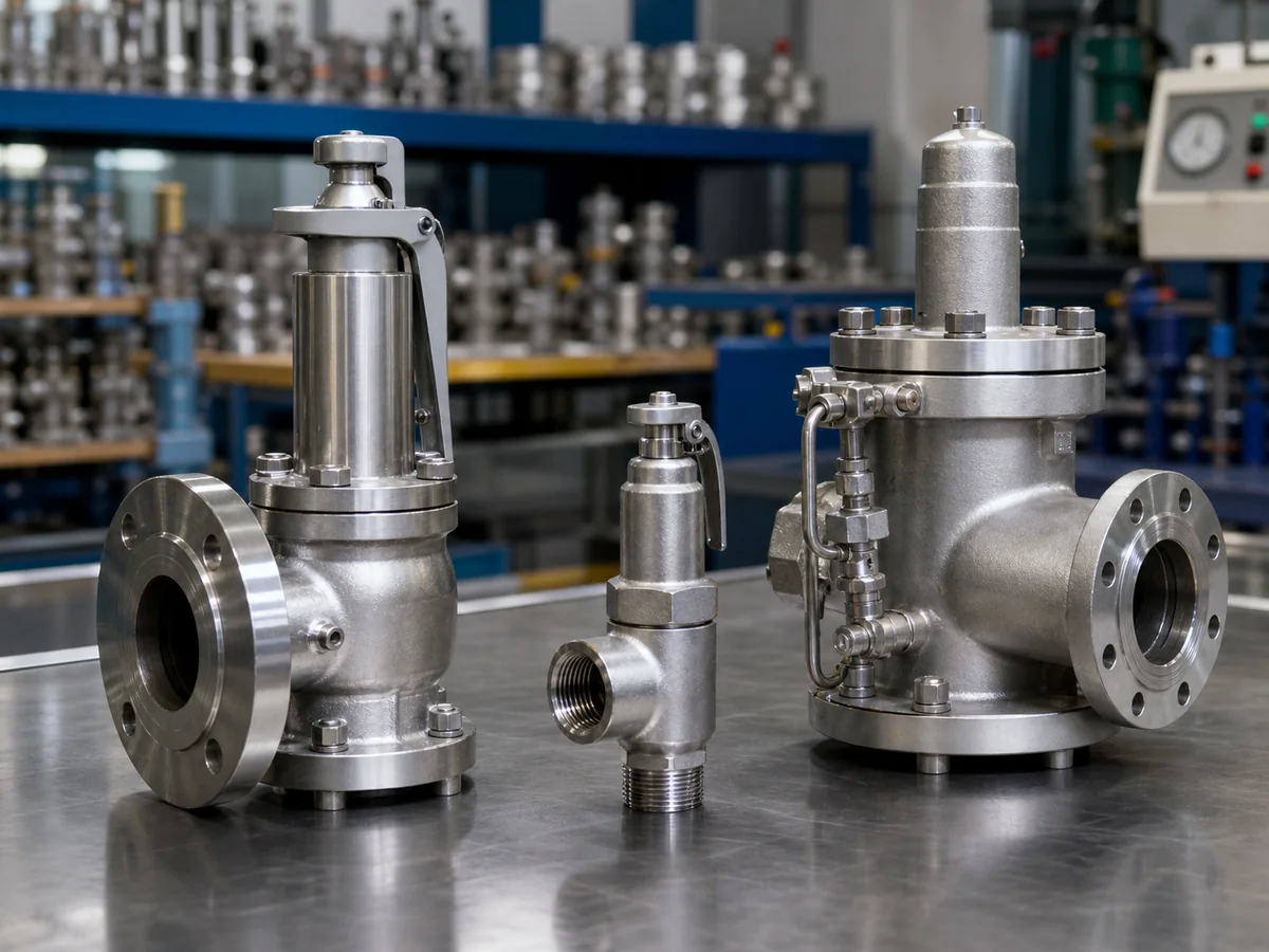
Quick Answer: The 3 Main Pressure Relief Valve Types The three main reclosing pressure relief valve constructions are conventional spring-loaded, balanced bellows, and pilot-operated designs. A conventional spring-loaded valve is usually the starting point for clean service with low or stable back pressure. A balanced bellows valve is considered when variable outlet pressure or spring-chamber …
Quick Answer: The 3 Main Pressure Relief Valve Types
The three main reclosing pressure relief valve constructions are conventional spring-loaded, balanced bellows, and pilot-operated designs. A conventional spring-loaded valve is usually the starting point for clean service with low or stable back pressure. A balanced bellows valve is considered when variable outlet pressure or spring-chamber exposure makes a conventional design less suitable. A pilot-operated valve is considered for selected clean, high-pressure, tight-shutoff, large-capacity, or back-pressure-sensitive duties. Safety valve, relief valve, and safety relief valve describe service or opening terminology; they are not separate control constructions.
Selection sequence: start with the protected equipment and governing overpressure scenario, then confirm the fluid phase at relieving conditions, set pressure, allowable overpressure and accumulation, required relieving capacity, manufacturer-supported or certified capacity, inlet pressure loss, superimposed and built-up back pressure, materials, seat design, installation, testing, and applicable code route. A familiar model number or matching flange size is not enough.
Pressure-protection boundary: pressure class and flange rating describe component pressure-temperature capability. They do not establish the correct set pressure, allowable accumulation, effective orifice, or emergency capacity. A valve can pass a bench set-pressure test and still be unsuitable because the selected orifice is too small, the inlet line is restrictive, the outlet header creates excessive back pressure, or the construction is incompatible with the medium.
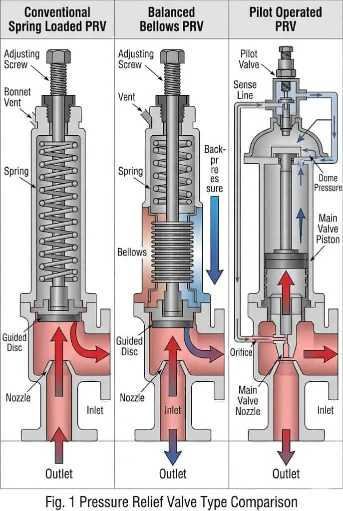
The three main reclosing constructions use different force-balance and control arrangements. Final selection still depends on the relief scenario, capacity, back pressure, materials and installed piping.
Selection Question
Engineering Decision
Evidence Required
What must be protected?
Identify the vessel, boiler, piping, exchanger, pump, tank or process skid and its pressure boundary.
Equipment datasheet, MAWP/design basis, applicable code and tag.
Why can pressure rise?
Establish the governing credible relief scenario rather than copying the old valve.
Approved relief calculation and scenario revision.
What must be discharged?
Confirm gas, steam, vapor, liquid, flashing or two-phase condition at relief.
Composition, properties, relieving pressure and temperature.
How much flow is required?
Compare required load with supported or certified capacity for the identified valve configuration.
Orifice, coefficient/capacity basis and manufacturer documentation.
How will the installation affect it?
Review inlet loss, outlet resistance, back pressure, drainage, reaction force and simultaneous relief.
Piping layout, line data and discharge-system calculation.
Can it survive and be maintained?
Review wetted and exposed materials, seat design, inspection access, spares and repair authorization.
Material certificates, test plan, maintenance route and documentation list.
A valve-type decision should follow the pressure-protection duty from the protected equipment through capacity, installation and lifecycle controls.
Pressure Relief Valve, Safety Valve, Relief Valve, and Safety Relief Valve: What Is the Difference?
Pressure Relief Valve as the General Category
A pressure relief valve is a broad term for a self-actuated or controlled device used to protect pressurized equipment from excessive pressure. In many process projects, PRV is used as an umbrella label for safety valves, relief valves and safety relief valves. The abbreviation is not a complete specification and can also mean pressure-reducing valve in utility, HVAC, water and control documents.
Document-control rule: RFQs, P&IDs, equipment lists and maintenance instructions should write the full function whenever PRV could be misunderstood. The approved datasheet should identify the protected equipment, service fluid, opening characteristic, construction, set pressure, required capacity, supported capacity, code marking, test basis and document package.
Safety Valve for Steam, Gas, and Vapor Service
In common API-oriented and process-industry usage, a safety valve is associated with rapid or pop opening in compressible-fluid service such as steam, air, gas or vapor. The valve must develop sufficient lift and supported capacity quickly enough to keep pressure within the approved equipment and code boundary, then reseat after pressure falls through the specified blowdown range.
This gas-and-steam distinction is useful for early communication, but it is not a universal international naming rule. ISO product terminology can use “safety valve” irrespective of fluid. Final approval must therefore rely on the exact model, opening characteristic, capacity basis, materials, test records and adopted code—not the catalogue name alone.
Relief Valve for Liquid Service
In common process-industry usage, a relief valve is associated with liquid service and a more proportional increase in lift as inlet pressure rises. Typical duties include blocked positive-displacement pump discharge, hydraulic protection, trapped-liquid thermal expansion and liquid-filled equipment. Liquid density, viscosity, flashing potential, reaction forces and discharge destination must be included in selection.
A small thermal-relief case and a process case with continuous pump or heat input are not equivalent. A valve copied from steam or gas service can open near the requested pressure yet remain unstable, generate hydraulic shock or lack adequate liquid capacity. The approved liquid relief calculation and manufacturer-supported liquid data control the decision.
Safety Relief Valve for Broader Process Applications
A safety relief valve may be used in broader process services where the valve must handle gas, vapor, liquid, or a combination depending on the design and project requirement. The term alone does not prove suitability. The service medium, relieving scenario, required capacity, valve construction, material, and applicable standard must still be verified.
PSV, PRV, SRV, and Project Terminology Control
PSV, PRV, and SRV are often used differently across projects, industries, and regions. A procurement document should not rely on abbreviation alone. The datasheet should define the required valve type, service medium, set pressure, required relieving capacity, certification basis, test requirement, and documentation scope. For a deeper terminology discussion, see ZOBAI’s PRV vs PSV vs Safety Valve vs Relief Valve guide.
Term / Type
Selection Layer
Typical Use
What It Does Not Tell You
Pressure Relief Valve / PRV
General category
Broad overpressure protection terminology
Exact construction, certification basis, or medium suitability
Pressure Safety Valve / PSV
Project terminology
Common in process and pressure vessel specifications
Whether the valve is spring loaded, bellows balanced, or pilot operated
Safety Valve
Application category
Commonly steam, gas or vapor in API-oriented usage
Required capacity, materials, or back pressure limits
Relief Valve
Application category
Commonly liquid duty in API-oriented usage
Whether it is suitable for compressible service
Spring-loaded / Balanced Bellows / Pilot-operated
Construction layer
How the main valve closing force or control pressure is arranged
Whether the selected model meets the actual capacity and code requirement
Procurement warning: terminology errors can create real compliance and procurement risk. For example, a steam safety valve, a liquid relief valve, and a safety relief valve may all be called “PRV” in informal communication, but they may not share the same opening behavior, certification basis, seat tightness expectation, or sizing method. The valve datasheet should define both the terminology layer and the construction layer before price comparison.
Conventional Spring Loaded Pressure Relief Valves
How a Spring Loaded Valve Opens and Reseats
A conventional spring loaded pressure relief valve uses spring force to keep the disc seated against the nozzle. When inlet pressure creates enough upward force to overcome the spring force, the valve opens and discharges fluid. As system pressure falls, the spring force pushes the disc back toward the seat and the valve reseats.
Set pressure determines when the valve starts to relieve under specified conditions. Overpressure helps the valve reach rated lift and capacity. Blowdown affects the difference between opening and reseating pressure. These parameters affect whether the valve protects the equipment and whether it returns to a stable closed position after the event.
The simplified closed-valve force balance can be expressed as inlet pressure acting over an effective area against spring preload and other closing forces. Once the disc lifts, the effective area, spring compression and fluid reaction forces change, so the motion becomes dynamic. Huddling geometry, guide friction, inlet pressure decay and outlet pressure can affect lift and reseating. This principle explains operation; it is not a sizing equation.
Conventional Valve Review Boundary
Confirm operating pressure margin below set pressure.
Confirm the spring range and service-temperature correction basis.
Calculate inlet pressure loss during rated flow, not only static line loss.
Define superimposed and built-up back pressure separately.
Check whether the discharge is atmospheric, closed or connected to a flare/header.
Verify supported capacity for the actual fluid and relieving conditions.
Pressure Term
Engineering Meaning
Why It Affects Selection
Set pressure
The pressure at which the valve is adjusted to start relieving under specified conditions
Determines when overpressure protection begins
Overpressure
Pressure rise above set pressure during relieving
Influences whether the valve reaches rated lift and capacity
Accumulation
Pressure increase of the protected equipment during a relieving event
Must be checked against the applicable equipment design basis and code requirement
Blowdown
Difference between opening pressure and reseating pressure
Affects stable reseating, cycling risk, and leakage after relief
Best Applications for Conventional Spring Loaded Valves
Conventional spring-loaded valves are often the preferred starting point for clean service, low or stable back pressure, straightforward discharge piping, and sites that value simple inspection and spare-parts control. They are not a lower-grade option: in the correct duty, a spring-loaded safety valve can provide the most transparent force balance, repair route and lifecycle cost.
Limits Under Back Pressure, Dirty Service, and Close Operating Pressure
Conventional valves can be sensitive to outlet back pressure because outlet pressure may affect the force balance across the disc assembly. Dirty or corrosive media may also affect the guide, disc, nozzle, spring chamber, or seating surfaces. If normal operating pressure is too close to set pressure, the valve may simmer or leak, especially if the seat condition or operating margin is not suitable.
Common Selection Mistakes
Selection warning: a conventional valve originally approved for atmospheric discharge may become unsuitable if a later project connects it to a common recovery or flare header. The valve may still pass a bench set-pressure test while the installed outlet resistance changes lift, blowdown and stability. Discharge-system modification therefore requires a new back-pressure and capacity review.
Balanced Bellows Pressure Relief Valves
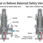
How the Bellows Reduces Back Pressure Influence
A balanced bellows pressure relief valve uses a metallic bellows and balancing geometry to reduce the effect of outlet pressure on the disc assembly within the manufacturer’s stated limits. In applicable designs, the bellows also separates the spring chamber from direct process exposure. It should not be treated as a hermetic secondary containment barrier.
“Balanced” does not mean that outlet pressure can be ignored. Back pressure can still affect discharge flow, capacity correction, reaction forces, blowdown and system stability. The bonnet vent is part of the pressure reference and failure-detection arrangement; plugging it or routing it to a pressurized destination without design approval can defeat the intended behavior.
When Balanced Bellows Valves Should Be Considered
A balanced bellows safety valve should be considered when outlet back pressure is variable, when the valve discharges into a closed system or common header, or when the process fluid may corrode or contaminate the spring chamber. It may also be reviewed for wet corrosive vapor, toxic fluid, or dirty vapor service where spring chamber protection is important.
Bellows Material, Bonnet Vent, and Maintenance Risks
The bellows is a thin-wall flexible component. It must be checked for corrosion, temperature, fatigue, vibration, and material compatibility. The bonnet vent arrangement must also be understood during installation and maintenance. Plugging a required vent can change valve behavior or hide bellows leakage.
Bellows Review Item
Why It Matters
Typical Error
Bellows alloy
Thin convolutions can be more sensitive to corrosion and fatigue than the valve body.
Specifying only body material.
Bonnet vent
Supports the intended reference pressure and can reveal bellows leakage.
Plugging, tubing to an unsuitable destination or obstructing the vent.
Temperature and cycles
Thermal movement and repeated flexing affect fatigue life.
Ignoring cycling service or hot/cold transients.
Failure consequence
A failed bellows may change force balance and expose the bonnet/spring chamber.
No inspection method or contingency for leakage.
Capacity basis
Outlet pressure can still require model-specific capacity correction.
Assuming “balanced” means no back-pressure limit.
When a Bellows Design Is Not Enough
Balanced bellows construction reduces back pressure influence, but it does not remove the need for discharge system review. Excessive built-up back pressure, poor inlet piping, undersized outlet piping, wrong bellows material, or lack of maintenance can still cause unstable operation and leakage.
Illustrative case—common header increased built-up back pressure: A conventional valve began to chatter after several relief devices were connected to a common discharge header. The piping change was reviewed for mechanical fit but not for simultaneous relief flow. The resulting header pressure exceeded the original operating basis. The corrective action was to recalculate outlet pressure drop, inspect the disc, seat and guide, and evaluate a balanced bellows or suitable pilot-operated design. The preventive control is to include header pressure, simultaneous-relief assumptions and valve back-pressure limits in every modification review.
Pilot Operated Pressure Relief Valves
How Pilot Control and Dome Pressure Work
A pilot-operated pressure relief valve uses a pilot to control pressure above the main-valve piston or diaphragm. During normal operation, dome pressure acting over a larger effective area helps keep the main valve closed. At the specified opening condition, the pilot changes or vents dome pressure so inlet pressure can lift the main valve.
The pilot controls the main valve; it does not normally provide the principal relieving area. Response depends on pilot type, piston or diaphragm seals, internal leakage, guide friction, sensing pressure, pilot exhaust pressure and the association between the pilot and main valve. Bench verification of the pilot set point alone does not prove that the complete assembly will open and pass the required flow.
ISO 4126-4 gives product requirements for pilot-operated safety valves, but it is not an application standard. The project still has to establish medium cleanliness, sizing, back pressure, sensing and exhaust routing, installation and maintenance limits.
When Pilot Operated Valves Are a Better Candidate
Pilot operated valves may be considered for selected high-pressure gas service, large required capacity, tight shutoff close to set pressure, or some back-pressure-sensitive systems. They can reduce leakage in suitable service and may reduce the mechanical load associated with very large spring designs.
Medium Cleanliness, Pilot Passages, and Sensing Line Risks
Pilot operated valves are not always better. Pilot passages, sensing lines, seals, and small control components can be sensitive to dirty, sticky, freezing, crystallizing, or polymerizing media. A valve that performs well on clean gas may not be suitable for dirty process vapor without filtration, maintenance planning, or a different valve type.
Backflow and sensing boundary: where discharge-header pressure can exceed inlet or dome pressure, the exact pilot configuration and any manufacturer-approved backflow protection must be checked. Remote sensing can reduce the effect of inlet-line loss only when the sensing connection is correctly located, continuously available, protected from blockage or freezing, and controlled against accidental isolation.
Snap-Acting vs Modulating Pilot Operated Designs
A snap-acting pilot opens quickly when set pressure is reached. A modulating pilot controls the main valve more gradually according to pressure rise and required flow. The selection depends on fluid state, relief scenario, allowable overpressure, discharge system, and process stability requirement.
Pilot Feature
Meaning
Selection Concern
Snap-acting
Creates a rapid change in dome pressure and main-valve lift.
Dynamic reaction, header pressure and blowdown behavior.
Modulating
Controls dome pressure progressively as inlet pressure changes.
Stable partial lift, process fluctuations and minimum flow behavior.
Flowing pilot
Control fluid continues through part of the pilot circuit during relief.
Pilot discharge destination, freezing, fouling and fluid consumption.
Non-flowing pilot
Continuous pilot flow is restricted after the control state is established.
Internal leakage, trapped pressure and response characteristics.
Internal sensing
Pilot senses pressure from the valve inlet/internal passage.
Pressure loss at the valve inlet and local pressure representation.
Remote sensing
Pilot senses pressure from a separate protected-equipment tapping.
Condensate, freezing, isolation, heat tracing, length and vibration.
Illustrative case—pilot passages fouled in a dirty process stream: A pilot-operated valve passed its initial bench test but later showed delayed and unstable response. Fine particles and deposits restricted the pilot passage and sensing path, so dome pressure did not change as intended. The correction was to clean and function-test the pilot and main valve, review filtration, drainage and sensing-line routing, and reassess whether a direct spring-loaded design was more robust. The prevention is to treat medium cleanliness and maintenance access as primary selection criteria, not after-sales details.
Other Pressure Relief Devices and Special Valve Types You May Encounter
Power-Actuated Pressure Relief Valves
Power-actuated pressure relief valves use an external actuation or control system rather than relying only on direct spring force or process-powered pilot action. They are special protective devices and must be reviewed as a complete system, including sensors, logic, power or stored energy, redundancy, failure response, proof testing and applicable code acceptance.
ISO 4126-5 addresses controlled safety pressure relief systems (CSPRS). A CSPRS should not be described as an ordinary pilot-operated valve merely because both use a control element; the protective logic, actuation energy and fail-safe architecture are different approval layers.
Temperature and Pressure Relief Valves
Temperature and pressure relief valves are commonly associated with water heaters, thermal systems, or equipment requiring both temperature and pressure protection. They are not a general substitute for process safety valves used on pressure vessels or chemical systems.
Vacuum Relief and Breather Valves
Vacuum relief and breather valves protect low-pressure tanks or storage systems against vacuum, pressure, or breathing losses. They usually belong to tank protection rather than high-pressure PSV service. Selection must consider tank design pressure, vacuum rating, breathing rate, venting scenario, and environmental requirements.
Rupture Discs as Related Pressure Relief Devices, Not Valves
A rupture disc is a non-reclosing pressure relief device. It can be used alone or in combination with a safety valve in selected applications, but it is not a valve because it does not reseat after opening. If a rupture disc is installed upstream of a valve, the effect on pressure drop, inspection, leakage detection, and relief capacity must be reviewed.
Where a rupture disc is installed upstream of a valve, the interspace must be arranged so disc leakage or premature rupture can be detected and pressure cannot build unnoticed between the devices. The disc holder, orientation and combination-capacity basis must match the approved design. A downstream rupture disc may isolate the valve outlet from corrosive or contaminated headers, but it also changes the outlet pressure condition and inspection requirements.
Sanitary, Jacketed, and Special-Service Relief Valves
Sanitary, jacketed, cryogenic, high-pressure, or special-service relief valves may be required for specific industries or process conditions. These designs should be selected by service requirement, cleanability, temperature, material compatibility, and documentation needs rather than by appearance or catalog category alone.
How to Choose by Medium: Steam, Gas, Vapor, Liquid, Two-Phase, or Corrosive Service
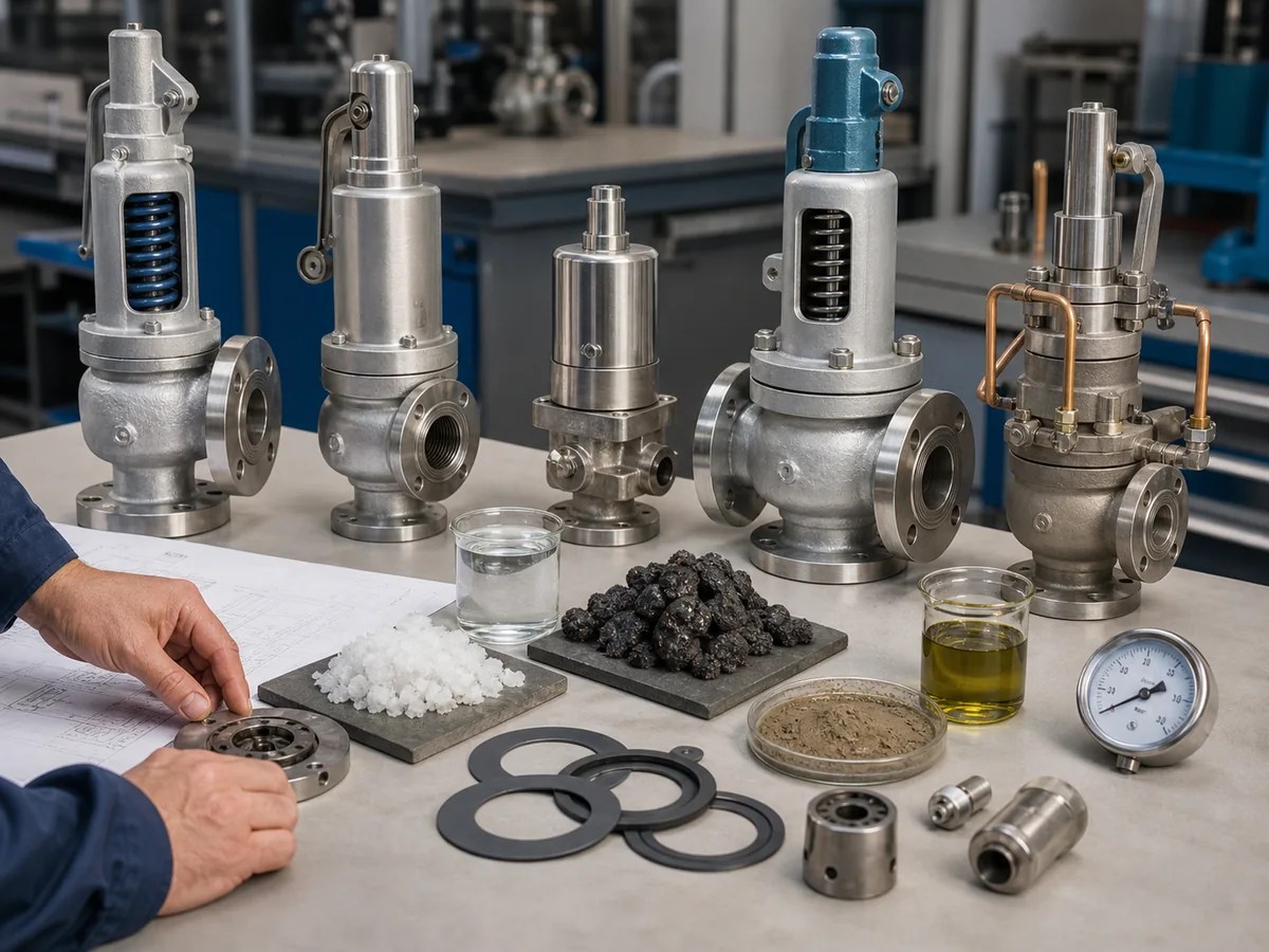
Medium-to-valve matching should consider steam, gas, vapor, liquid, two-phase, corrosive, dirty, or crystallizing service before selecting a pressure relief valve type.
Steam Service and Boiler-Related Applications
Steam service requires attention to set pressure, blowdown, temperature, discharge reaction force, drainage, and code requirements. Boiler-related applications may require different rules from process vessel applications. A valve selected for clean gas service should not be assumed suitable for saturated or superheated steam without checking materials, trim, seat design, and test requirements.
Illustrative case—high-temperature steam configuration copied from lower-temperature service: A replacement valve reached the requested set pressure but developed early leakage after repeated hot operation. The review found that spring environment, trim, seat and drainage had been copied from a cooler gas application. The correction was to verify actual operating and relieving temperatures, bonnet arrangement, materials, condensate drainage and test-pressure correction. The prevention is to define steam condition and thermal exposure in the RFQ rather than specifying only pressure and flange size.
Gas and Vapor Service
Gas and vapor service is common for safety valves and safety relief valves. Selection should confirm the required relieving capacity, molecular weight or vapor properties, relieving temperature, allowable overpressure, back pressure, and discharge path. Tight shutoff may be important when operating pressure is close to set pressure.
Liquid Relief Service
Liquid relief service may involve thermal expansion, blocked discharge, pump protection, or liquid-filled equipment protection. Hydraulic forces and stability behavior can differ from gas or vapor service. The valve type should be selected using liquid service data rather than by copying a vapor valve selection.
Two-Phase or Flashing Service
Two-phase or flashing service requires a project-specific engineering review because neither a single-phase gas equation nor a single-phase liquid shortcut may represent the actual flow. The inlet thermodynamic state, flashing path, vapor fraction, relieving pressure and temperature, outlet pressure and manufacturer-supported method must be defined before the valve construction is confirmed.
ISO 4126-10:2024 addresses sizing of safety valves and bursting discs for gas/liquid two-phase flow. Its availability does not remove the need to select the project method, confirm the valve manufacturer’s acceptance and evaluate inlet loss and discharge-system loads.
Corrosive, Sour, Dirty, or Crystallizing Media
Corrosive and dirty service affects more than the valve body. Nozzle, disc, guide, spring, bellows, pilot internals, gaskets, and soft seals may all be exposed to damage. Sour service, chloride-containing streams, acid vapor, wet corrosive gas, and crystallizing media can create sticking, leakage, corrosion, or pilot blockage. For related applications, see ZOBAI’s corrosive service safety valve page.
Medium / Service
Suitable Valve Types to Review
Key Risk
Required Review
Steam
Safety valve, spring loaded safety valve
Temperature, discharge reaction force, drainage
Set pressure, blowdown, material, boiler or vessel code basis
Clean gas or vapor
Spring loaded, pilot operated, safety relief valve
Body, trim, bellows, spring, gasket, and seal compatibility
Dirty or crystallizing medium
Spring loaded or special design for review
Pilot blockage, sticking, seat damage
Medium cleanliness, flushing, inspection, and maintenance plan
How Back Pressure Changes Valve Type Selection
Back pressure changes valve type selection. Conventional, balanced bellows, and pilot operated valves respond differently under low, variable, or high built-up back pressure.
Back-Pressure Term
Definition
Why It Changes Selection
Superimposed back pressure
Outlet pressure present before the valve opens; it may be constant or variable.
Can shift the effective opening condition and pilot reference depending on design.
Built-up back pressure
Outlet pressure generated by flow through the discharge system after opening.
Can reduce lift, change capacity, increase chatter risk and delay reseating.
Total back pressure
The combination of superimposed and built-up components during relief.
Must be compared with the manufacturer’s design and capacity limits.
Conventional Valves Under Low or Stable Back Pressure
Conventional spring loaded valves can be suitable when back pressure is low, stable, and within the acceptable range for the selected design. They become riskier when outlet pressure is high, variable, or connected to a common discharge header.
Balanced Bellows Valves for Variable Back Pressure
Balanced bellows valves are commonly reviewed when back pressure is variable or when the valve discharges into a closed header or flare system. They reduce back pressure influence but still require outlet system review, bellows material review, and bonnet vent consideration.
Pilot Operated Valves Under Selected Back Pressure Conditions
Some pilot operated valves can handle selected back pressure conditions better than conventional designs, but this depends on the pilot configuration, dome pressure behavior, sensing line arrangement, and manufacturer data. They should not be selected only because the back pressure is high.
Common Discharge Header and Flare System Review
Common discharge headers and flare systems can create superimposed or built-up back pressure. If additional relief devices are added, the header pressure during simultaneous relief can increase. The valve type, capacity, and stability should be reviewed whenever the discharge system changes.
Back Pressure Condition
Conventional Valve
Balanced Bellows Valve
Pilot Operated Valve
Engineering Note
Low, stable back pressure
Often suitable
May be unnecessary
Usually not required only for back pressure
Confirm capacity and installation
Variable superimposed back pressure
Higher risk
Often considered
Design-specific review
Manufacturer data is required
High built-up back pressure
Often limited
May reduce influence within limits
Design-specific review
Outlet system calculation is critical
Common discharge header
Requires careful review
Often a stronger candidate
May be suitable in selected services
Simultaneous relief assumptions matter
Capacity, Orifice Area, and Why Connection Size Is Not Enough
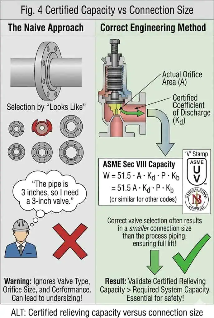
Connection size only confirms piping fit. Certified relieving capacity, orifice area, inlet pressure loss, and outlet back pressure determine whether the valve can protect the equipment.
Required Relieving Capacity Comes from the Relief Scenario
Required relieving capacity is determined by the credible overpressure scenario, not by pipe size alone. Fire exposure, blocked outlet, control valve failure, thermal expansion, heat exchanger tube rupture, utility failure, or process upset can produce different relieving loads.
Certified Relieving Capacity and Orifice Area
Required relieving capacity comes from the governing relief scenario. Manufacturer-supported or certified capacity shows what the identified valve model, orifice, fluid basis and relieving condition can discharge. The selected capacity must equal or exceed the approved required load after applying the applicable sizing and correction basis.
Orifice boundary: a letter-designated or nominal effective orifice is a sizing and product-identification input, not proof of the installed capacity by itself. Two valves with the same flange connections can have different orifices, lift, coefficients and certified capacities. Conversely, selecting an unnecessarily large orifice can increase instability and chatter risk when the system cannot sustain the corresponding flow.
Evidence
What It Can Support
What It Cannot Prove Alone
Set-pressure certificate
The adjusted opening characteristic under stated test conditions.
Adequate emergency capacity or stable installed performance.
Connection size and pressure class
Mechanical interface and pressure-temperature rating.
Effective orifice, coefficient or relieving capacity.
Certified/documented capacity
Supported performance for an identified model, fluid and pressure basis.
That the project relief load or scenario is correct.
Seat-tightness report
Leakage under the specified test method and pressure.
Set-pressure selection, capacity, blowdown or back-pressure suitability.
Legacy valve tag
Historical identity and some prior design information.
Suitability after process, equipment or piping modifications.
Inlet Pressure Loss and Outlet System Resistance
Inlet pressure loss can cause unstable opening and chatter. Outlet system resistance can create built-up back pressure and reduce stable relieving performance. These system effects should be reviewed together with valve sizing, not after the valve has been purchased.
Field Scenario: Correct Flange Size but Insufficient Capacity
Illustrative case—correct flanges, insufficient supported capacity: A replacement valve matched the old inlet, outlet, pressure class and set pressure, so it was initially considered interchangeable. The protected process had been expanded, however, and the governing relief load had increased while the original calculation was never revised. The replacement was stopped before installation, the scenario and required capacity were recalculated, and a valve with the appropriate orifice and supported capacity was selected. The preventive control is to trigger a relief-capacity review whenever process duty, equipment, heat input or discharge piping changes.
Materials, Seat Design, and Temperature Limits
Body and Trim Material Selection
Body material alone does not define valve suitability. Nozzle, disc, guide, spring, bellows, gaskets, pilot internals, and soft goods may all require separate review. Material compatibility affects corrosion, sticking, leakage, and service life.
Soft Seat vs Metal Seat
Soft seats can improve tightness in suitable service, but they must be checked for temperature, chemical compatibility, compression set, swelling, aging, and maintenance conditions. Metal seats may be better for high temperature or aggressive media, but leakage expectations must be defined clearly.
Springs, Bellows, Guides, Seals, and Pilot Internals
Internal components can fail even when the valve body remains sound. Springs may corrode, bellows may crack or fatigue, guides may stick, seals may degrade, and pilot passages may block. These risks affect maintenance interval, spare parts, shutdown planning, and lifecycle cost.
Component
Failure Mechanism to Review
Potential Result
Nozzle and disc
Corrosion, erosion, deposits and poor surface condition.
Seat leakage, altered flow area and unreliable reseating.
Guide and spindle/piston
Galling, corrosion, solids and thermal distortion.
Sticking, delayed opening or misaligned closure.
Spring
Corrosion, relaxation, incorrect range and excessive temperature.
Set-pressure drift and reduced operating reliability.
Bellows
Thin-wall corrosion, fatigue, vibration and pressure cycling.
Loss of balancing action and bonnet exposure.
Soft seat and seals
Swelling, hardening, compression set and chemical attack.
Dome-pressure loss, leakage and short maintenance interval.
Pilot internals and tubing
Small-passage blockage, H₂S cracking, condensate or freezing.
Delayed actuation, unstable control or failure to reset.
Corrosion, Sticking, Leakage, and Lifecycle Cost
Component-level material control: accepting the body alloy does not confirm compatibility of the nozzle, disc, guide, spindle or piston, spring, bellows, pilot internals, tubing, gaskets or soft seals. Damage to these smaller components can cause sticking, set-pressure drift, loss of dome pressure or leakage while the pressure-retaining body remains apparently sound.
For H₂S-containing oil-and-gas-production environments, ISO 15156 / NACE MR0175 addresses cracking-resistant material selection within its defined scope. It does not replace general corrosion, chloride, acid, erosion, polymerization or compatibility assessment. Service life remains dependent on composition, pressure, temperature, back pressure, valve construction, inspection history and installed conditions.
Installation and Maintenance Factors That Affect Valve Choice
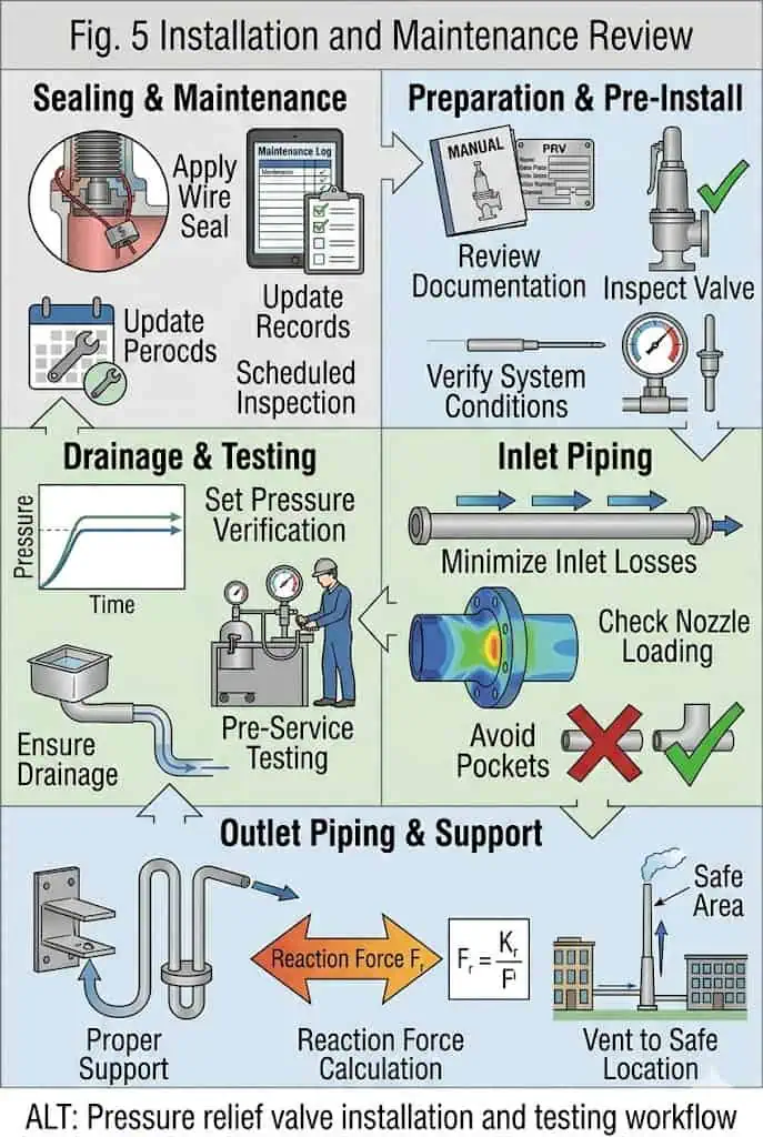
Installation and maintenance review should include inlet pressure loss, outlet piping, drainage, reaction force, back pressure, set pressure testing, seat tightness testing, and final sealing.
Inlet Piping and Pressure Loss
Even the correct valve can perform poorly if inlet piping causes excessive pressure loss. Long inlet lines, small branches, sharp fittings, or poor installation layout can cause chatter, reduced lift, or unstable opening. Inlet pressure loss should be reviewed before final valve approval.
Keep the inlet route direct and mechanically supported.
Check branch, nozzle, reducer, gasket and fitting restrictions at relieving flow.
Avoid liquid pockets where the service or climate can create freezing or slugging.
Do not transfer unsupported outlet loads or thermal expansion into the valve body.
Confirm valve orientation, drains, bellows vent and pilot sensing/exhaust routing.
Recalculate the system after capacity, header or equipment modifications.
Outlet Piping, Reaction Force, Drainage, and Back Pressure
Outlet piping affects built-up back pressure, discharge reaction force, drainage, noise, and maintenance access. Common headers and flare systems require additional review because they may impose variable outlet pressure during relief events.
Testing, Recalibration, and Sealing After Maintenance
After maintenance or repair, the valve should not be returned to service based only on visual inspection. Set pressure, seat tightness, sealing, and documentation should be checked according to the applicable plant procedure, project specification, and local jurisdictional requirement. Where National Board / NBIC or VR repair requirements apply, the repair route and documentation scope should be confirmed before the valve is returned to service.
Return-to-Service Checks After Repair or Internal Adjustment
Record the as-found set pressure, leakage, contamination and damaged parts before cleaning.
Verify replacement spring, nozzle, disc, guide, bellows, pilot parts and seals against controlled part identification.
Document seat machining, ring adjustment and any change that can affect lift or blowdown.
Perform the required pressure-boundary, set-pressure, functional and seat-tightness tests.
Match reports, tag, nameplate and serial number; restore locking, sealing and required markings.
Confirm that the original system cause—such as inlet loss, back pressure, corrosion or vibration—has been corrected before installation.
Where the jurisdiction or owner specification requires National Board/NBIC controls, repair should follow the applicable VR authorization scope. A VR repair route controls the repair organization and quality system; it does not replace the relief calculation or installed-system review.
Spare Parts, Repair Route, and Documentation
Maintenance capability is part of valve selection. A pilot operated or bellows balanced valve may solve one operating problem but create higher spare parts and inspection requirements. Procurement should confirm test reports, material certificates, nameplate data, inspection records, and repair documentation before purchase.
Inspection and recalibration intervals should be risk-based and consistent with regulation, owner policy, as-found history and service severity. A fixed universal interval is not technically defensible for every valve. Dirty, corrosive, polymerizing, high-temperature, frequently cycling or high-consequence duties generally need closer surveillance than clean, stable service, but the final interval belongs in the site inspection program.
Selection Mistake
Typical Cause
Field Symptom
Consequence
Prevention
Selected by connection size only
No capacity review
Valve fits piping but fails duty
Insufficient protection
Check required and certified capacity
Ignored back pressure
Outlet system not reviewed
Chatter or unstable reseating
Seat damage and leakage
Review superimposed and built-up back pressure
Wrong valve type for dirty medium
Pilot passages not considered
Delayed or unstable response
Maintenance and safety risk
Review medium cleanliness and pilot protection
Wrong soft seat material
Temperature or chemical limit ignored
Leakage or seal failure
Product loss and downtime
Confirm material compatibility
No recalibration after repair
Incomplete maintenance procedure
Set pressure drift
Nuisance lifting or unsafe margin
Perform documented testing and sealing
Pressure Relief Valve Type Selection Table
Quick Engineering Comparison by Service Condition
The following table is for early screening. It does not replace formal sizing, code review, or manufacturer confirmation.
Confirm the protected equipment and approved pressure boundary.
Identify all credible scenarios and select the governing required load.
Establish fluid phase and properties at the relieving condition.
Define set pressure, overpressure/accumulation basis and operating margin.
Calculate inlet loss and total back pressure for the installed arrangement.
Screen conventional, bellows, pilot and special-device limitations.
Verify capacity, materials, seat, tests, markings and documents for the exact model.
Selection Notes for Procurement and EPC Review
Procurement should not freeze the valve type before the relief scenario, capacity, back pressure, and material requirements are checked. EPC review should also confirm installation layout, discharge system, and inspection documentation.
When to Ask the Manufacturer for Engineering Review
Ask for engineering review when the service is high pressure, high temperature, corrosive, dirty, two-phase, variable back pressure, connected to a common header, operating close to set pressure, or subject to special documentation requirements.
Candidate
Selection Layer
Operating Principle or Duty
Best Starting Conditions
Main Risk / Approval Note
Conventional spring-loaded
Construction
Direct spring force opposes inlet pressure
Clean service with low or stable back pressure and straightforward maintenance
Sensitive to inlet loss and outlet pressure; verify capacity and stability
Balanced bellows
Construction
Bellows reduces back-pressure force influence within design limits
Variable back pressure, closed headers or selected spring-chamber isolation duties
Bellows fatigue, vent routing and model-specific back-pressure limits
Pilot-operated
Construction
Pilot controls dome pressure above the main valve
Selected clean high-pressure, tight-shutoff, large-capacity or back-pressure-sensitive duty
Pilot fouling, seal leakage, sensing/exhaust errors and backflow conditions
Liquid relief duty
Application / opening duty
Typically proportional liquid relief
Thermal expansion, pump or liquid-system protection
Use the liquid or two-phase sizing basis; do not copy a gas selection
Safety relief valve
Application terminology
Product may support specified compressible and/or liquid duties
Process projects needing a documented multi-service product family
The name does not define construction, fluid certification or capacity
RFQ Checklist: Data Needed to Choose the Right Pressure Relief Valve
Process and Relief Scenario Data
The RFQ should define the protected equipment, relief scenario, process medium, fluid phase, operating condition, and whether the relief case is fire, blocked outlet, thermal expansion, control failure, tube rupture, or another credible scenario.
Pressure, Temperature, and Capacity Data
Provide normal operating pressure, set pressure, relieving pressure or allowable overpressure basis, operating temperature, relieving temperature, and required relieving capacity. Without these values, valve type and size cannot be responsibly confirmed.
Back Pressure, Installation, and Material Data
Provide superimposed back pressure, built-up back pressure, outlet piping data, inlet piping arrangement, flange standard, body material, trim material, seal requirement, corrosion risk, and discharge system description.
Standards, Testing, and Documentation Requirements
Confirm applicable project standards, test reports, seat tightness requirement, material certificates, inspection records, nameplate data, repair route, and any required third-party inspection before ordering.
Technical Approval Hold Point
Release Requirement
Relief basis approved
Protected equipment, governing scenario, load, units and calculation revision are identified.
Valve type approved
Construction is justified against medium, operating margin, back pressure and maintenance capability.
Capacity approved
Required load is below the supported capacity for the stated fluid and relieving conditions.
Installation approved
Inlet loss, outlet resistance, drainage, reaction loads, venting and sensing are reviewed.
Materials approved
Body, trim, spring, bellows, pilot parts, gaskets and seals are covered.
Document package approved
Datasheet, drawings, certificates, test records, nameplate and repair requirements are agreed before production.
Protected equipment type
Relief scenario
Medium and composition
Gas, vapor, steam, liquid, or two-phase service
Normal operating pressure
Set pressure requirement
Relieving temperature
Required relieving capacity
Superimposed back pressure
Built-up back pressure
Inlet and outlet connection size
Flange standard and pressure class
Body and trim material
Seat and seal requirement
Installation orientation
Discharge destination
Applicable code or project standard
Test and inspection documents
Protected equipment MAWP or approved pressure limit
Relieving pressure and allowable overpressure / accumulation basis
Required orifice or manufacturer-supported capacity basis
Operating pressure margin and expected pressure fluctuations
Blowdown or reseating requirement where specified
Seat-tightness acceptance basis
Pilot sensing and exhaust arrangement where applicable
Bellows vent arrangement where applicable
Repair authorization, recalibration, tagging and sealing requirements
FAQs About Types of Pressure Relief Valves and Selection
What are the main types of pressure relief valves?
The three main reclosing construction types are conventional spring-loaded, balanced bellows and pilot-operated valves. Safety valve, relief valve and safety relief valve describe service or opening terminology rather than separate control constructions. Thermal relief valves, T&P valves, rupture discs and vacuum devices cover specialized duties.
How do I choose the right pressure relief valve?
Start with the protected equipment and governing relief scenario. Then verify fluid phase, set pressure, allowable overpressure and accumulation, required and supported capacity, inlet loss, back pressure, materials, seat design, discharge routing, testing and the adopted code.
What is the difference between a safety valve and a relief valve?
In common API-oriented usage, a safety valve is associated with rapid opening in steam, gas or vapor service, while a relief valve is associated with proportional liquid relief. This is not a universal naming rule; the exact product definition and capacity basis control.
What is the difference between spring loaded and pilot operated pressure relief valves?
A spring-loaded valve uses direct spring force; a pilot-operated valve uses a pilot to control dome pressure above the main valve. Pilot operation can improve tightness or suit selected pressure/back-pressure duties, but it introduces small passages, seals, sensing and exhaust requirements.
When should I use a balanced bellows relief valve?
Consider a balanced bellows design when variable back pressure, a closed discharge header or process exposure of the spring chamber makes a conventional valve less suitable. Confirm the bellows alloy, bonnet vent, fatigue duty and manufacturer back-pressure limits.
Which pressure relief valve is best for back pressure?
There is no universal best type. Conventional valves suit low and stable back pressure; balanced bellows valves are often considered for variable back pressure; some pilot-operated designs suit selected higher or variable outlet pressures. The outlet-system calculation and model limits decide.
Can one valve type be used for steam, gas, and liquid?
Only when the exact design, opening characteristic, sizing method, capacity documentation, materials and code route support each duty. A common body or connection size does not prove multi-fluid suitability.
Is a pilot operated relief valve always better?
No. Pilot-operated valves can be strong candidates for selected clean, high-pressure, tight-shutoff or large-capacity service, but dirty, sticky, freezing, crystallizing or poorly maintained service can obstruct the pilot or sensing path.
Why is certified relieving capacity more important than connection size?
Connection size proves physical fit; supported or certified capacity proves flow performance for the identified model and conditions. The effective orifice, lift, fluid basis, pressure, temperature and back pressure must cover the approved required load.
What information should I send before requesting a quote?
Send the protected equipment, relief scenario, medium and phase, operating and set pressure, relieving pressure and temperature, required capacity, back pressure, inlet/outlet data, materials, seat requirement, code, tests and document list.
How often should a pressure relief valve be inspected or recertified?
No single interval is correct for every valve. Use regulation, owner policy, service severity, consequence, corrosion or fouling risk, operating cycles and as-found history. Leakage, chatter, fire exposure, process change or discharge-system modification can justify earlier review.
What is the difference between set pressure and overpressure?
Set pressure is referenced to the valve’s specified opening characteristic; overpressure is the rise above set pressure during relief. Overpressure helps develop lift and capacity and must follow the applicable scenario and code basis.
What is the difference between overpressure and accumulation?
Overpressure is referenced to set pressure; accumulation is referenced to the protected equipment’s MAWP or other approved pressure boundary. The permitted values depend on the equipment code and relief scenario.
How does inlet pressure loss affect a pressure relief valve?
Once flow starts, excessive loss between the protected equipment and valve can collapse inlet pressure at the valve. This can cause rapid cycling, chatter, reduced lift and seat damage even when the valve passed a static bench test.
Why can a pressure relief valve leak after installation?
Common causes include inadequate operating margin, seat contamination, piping strain, thermal distortion, damaged seating surfaces, wrong soft parts, unstable prior lifting or incorrect assembly. Diagnose the valve and system before changing the set adjustment.
What materials should be checked for corrosive or sour service?
Review the body, nozzle, disc, guide, spindle or piston, spring, bellows, pilot internals, tubing, gaskets and soft seals. ISO 15156/NACE MR0175 applies only within its H₂S oil-and-gas-production scope and does not replace general corrosion assessment.
What must be verified after a pressure relief valve is repaired?
Record the as-found condition, verify controlled parts, complete the required pressure-boundary, set-pressure, functional and seat-tightness tests, restore identification and seals, and correct the original system cause.
Does API 527 prove that a valve has enough relieving capacity?
No. API 527 addresses seat tightness for covered pressure relief valves. Capacity must be verified separately against the approved relief load, exact valve configuration, fluid conditions and installed back pressure.
Engineering Evidence Points to Verify Before Selection
Valve type should not be selected by connection size alone; required relieving capacity and certified relieving capacity must be reviewed against the relief scenario.
Back pressure can affect opening stability, effective capacity, chatter, reseating, and seat leakage; valve construction changes the sensitivity to this effect.
Seat tightness should be verified by the applicable project standard and purchaser requirement, especially for services operating close to set pressure.
Maintenance release should include set pressure, seat tightness, sealing, repair record, and documentation review, not only visual inspection.
Material compatibility should include body, nozzle, disc, guide, spring, bellows, gaskets, pilot internals, and soft seals where applicable.
Set pressure confirms an opening characteristic under stated conditions; it does not prove full lift, required capacity or stable installation.
Overpressure and accumulation use different reference pressures and should be tied to the applicable scenario and equipment code.
A balanced bellows or pilot-operated label does not eliminate back-pressure limits; the exact design and capacity basis must be confirmed.
Any change to process capacity, heat input, protected equipment, inlet piping or discharge header should trigger a documented relief-system review.
Bench testing cannot reproduce every installed dynamic effect; field piping, sensing, venting, drainage and structural loads remain design responsibilities.
Standards and Technical References Note
Standards cover different layers of the pressure-protection system. The project must use the edition adopted by the jurisdiction, owner and contract; the latest publication does not automatically govern an existing installation. Product compliance, relief-scenario engineering, installation analysis and repair authorization remain separate approvals.
Current-reference check: API’s official pages identify API 520 Part I as the 10th Edition and Part II as the 7th Edition. ISO 4126-1:2013, ISO 4126-4:2013 and ISO 4126-5:2013 were confirmed current in 2025. The 2025 NBIC places pressure-relief-device installation, inspection and repair guidance in Part 4. The adopted project edition still controls the purchase or installed equipment.
Repair-organization authorization and quality-system route where required.
Repair authorization does not replace selection, capacity or installation review.
ISO 15156 / NACE MR0175
Metallic-material selection for defined H₂S-containing oil-and-gas-production environments.
Not a universal corrosion standard for all refinery, chemical or chloride services.
Publishing and compliance note: do not claim ASME, API, ISO, PED, CE, National Board, NACE or other compliance unless the legal manufacturer, exact model, size, material, edition, marking, certificate scope and destination-market requirements have been verified. A generic catalogue statement is not order-specific evidence.
Engineering Review
This article supports preliminary pressure relief valve type screening, RFQ preparation and technical-bid review. Final selection requires the approved protected-equipment basis, governing relief calculation, exact valve model and configuration, supported capacity, inlet and outlet analysis, material review, inspection plan and applicable legal requirements.
Technical review scope: construction taxonomy, medium and phase, set pressure, overpressure and accumulation, required versus supported capacity, back pressure, inlet and outlet piping, materials, seat design, testing, repair and procurement data.
Evidence boundary: the field scenarios in this article are composite training examples used to explain common failure mechanisms. They are not identified ZOBAI project records, incident reports or design calculations.
Related Pressure Relief Valve Engineering Resources
Use these pages to continue from broad type screening into the four decisions that most often require separate engineering evidence: construction, capacity, back pressure and RFQ data.
Spring Loaded Safety Valves — for conventional direct-spring construction and product-level selection.
Need Help Choosing the Right Type of Pressure Relief Valve?
For a preliminary engineering review, send ZOBAI the protected equipment, governing relief scenario, medium and phase, operating pressure, set pressure, relieving pressure and temperature, required capacity, superimposed and built-up back pressure, inlet and outlet data, materials, seat requirement, discharge destination and applicable code. These inputs allow conventional spring-loaded, balanced bellows, pilot-operated and special-device candidates to be screened on the same technical basis.
Suggested RFQ attachments: P&ID, protected-equipment datasheet, approved relief calculation or scenario summary, discharge-system drawing, valve specification, material requirements, inspection and test plan, and required certification or repair basis.
Related Engineering Guides
Continue with these focused guides when the broader selection or maintenance review reaches the corresponding application question:
To provide the best experiences, we use technologies like cookies to store and/or access device information. Consenting to these technologies will allow us to process data such as browsing behavior or unique IDs on this site. Not consenting or withdrawing consent, may adversely affect certain features and functions.
Functional
Always active
The technical storage or access is strictly necessary for the legitimate purpose of enabling the use of a specific service explicitly requested by the subscriber or user, or for the sole purpose of carrying out the transmission of a communication over an electronic communications network.
Preferences
The technical storage or access is necessary for the legitimate purpose of storing preferences that are not requested by the subscriber or user.
Statistics
The technical storage or access that is used exclusively for statistical purposes.The technical storage or access that is used exclusively for anonymous statistical purposes. Without a subpoena, voluntary compliance on the part of your Internet Service Provider, or additional records from a third party, information stored or retrieved for this purpose alone cannot usually be used to identify you.
Marketing
The technical storage or access is required to create user profiles to send advertising, or to track the user on a website or across several websites for similar marketing purposes.