Compare extended and standard bonnet safety valves for cryogenic service, including thermal exposure, material limits, installation checks, and RFQ evidence.

An extended bonnet is not automatically required for every cryogenic safety valve.
Manufacturer-documented cryogenic relief valves exist with standard or closed bonnets as well as
extended-bonnet designs. Terms such as standard, conventional, closed, and extended are
manufacturer-specific descriptions and should not be treated as exact synonyms without checking
the proposed valve’s drawings, datasheet, materials, temperature limits, and qualification basis.
That makes the useful comparison more specific than “extended bonnet for colder service.”
Bonnet geometry is only one part of a pressure-relief-valve selection. The valve must still be
capable of opening at the required set pressure, remaining stable through the applicable
overpressure condition, providing the required relieving capacity, tolerating the actual back
pressure, reseating acceptably, and remaining compatible with the cryogenic medium and installed environment.
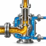
An extended bonnet can alter the distance and thermal path between the cold valve body and parts of
the upper operating assembly. But bonnet geometry alone does not establish that a valve is suitable
for LNG, liquid nitrogen, hydrogen, oxygen service, or another cryogenic duty.
The answer should come from the configured valve’s evidence—not from bonnet appearance, connection
size, or a generic “cryogenic” label.
Does Cryogenic Service Always Require an Extended Bonnet?
No. Cryogenic service by itself does not create a universal requirement for an extended bonnet.
A project specification, manufacturer requirement, applicable code, or local rule can still require a
particular configuration within its own scope.
A useful counterexample comes from original manufacturer documentation.
HEROSE identifies its Type 06002 as a cryogenic standard safety valve with a closed bonnet
,
with the published configuration covering cryogenic liquefied gases including LNG down to
−196°C. That shows that a closed-bonnet safety-valve design can be engineered for cryogenic relief
service; it does not establish the suitability of another valve with a superficially similar bonnet.
Manufacturer terminology also matters here. A closed bonnet describes the cited
product’s construction and should not automatically be treated as an exact synonym for every
“standard,” “conventional,” or “non-extended” bonnet used by other manufacturers.
Two opposite shortcuts are therefore unreliable:
- “Cryogenic means extended bonnet.”
- “A closed bonnet works in cryogenic service, so an extension is unnecessary.”
Neither is an adequate selection rule.
Temperature capability belongs to the exact configured valve. That configuration
can include the body and bonnet materials, spring, trim, seat or seal system, pressure rating,
permitted orientation, service medium, and other manufacturer-defined limits.
Standards require the same scope discipline.
ISO 21013-1
addresses the design, manufacture, and testing of pressure-relief valves for cryogenic service
within its stated scope. Its published scope should not be stretched into a universal bonnet rule,
nor should it be used as a substitute for determining the required relief capacity for the protected system.
The safer screening principle is therefore:
do not approve or reject a bonnet configuration because the service is merely labelled
“cryogenic.” Verify the exact valve against the actual relief duty.
That distinction prevents both unnecessary specification of an extended bonnet and acceptance
of a compact or standard construction merely because another manufacturer’s cryogenic valve uses one.
What Does an Extended Bonnet Actually Change in a Cryogenic Safety Valve?
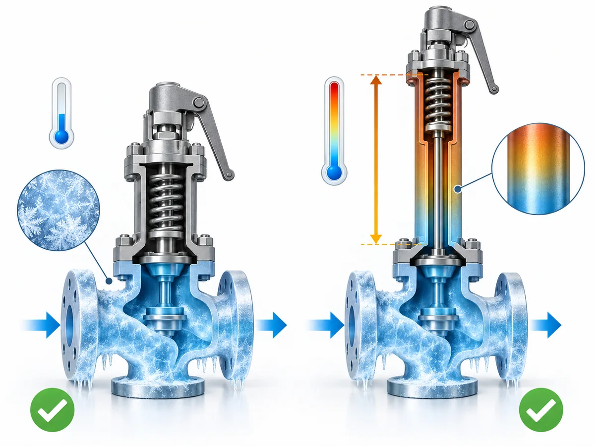
An extended bonnet changes the physical separation between the valve body or flow region
and parts of the upper valve assembly.
In designs where that extension is intended for thermal management, the extra separation changes
the heat-transfer path from the cold process region toward temperature-sensitive components farther
up the valve. The point is not to make the complete valve “warm.” It is to control the exposure
of the components that matter in that particular design.
This mechanism needs to stay design-specific.
Depending on the architecture, an upper assembly may contain a spring, spindle, guide, adjusting
components, seals, bellows, or other parts. It would therefore be too broad to say that every
extended bonnet exists simply to “keep the spring warm.”
IMI Process Automation’s Si 4
provides a useful safety-valve example. It is explicitly an extended-bonnet safety valve, and
the manufacturer lists cryogenic gas rectification among its applications. IMI also describes
other design reasons for the extended construction, including maintenance access and bellows
location. Even an actual extended-bonnet safety valve should therefore not be reduced to one
universal thermal function.
A useful conceptual sequence is:
cold process region → pressure-containing valve body → bonnet / extension → upper operating assembly.
When the extension changes the distance or construction between those zones, it can change
component temperature exposure. What it does not create is a universal
minimum-temperature rating.
This is also why guidance for cryogenic globe, gate, ball, or control valves must be used carefully.
Those designs often extend the stem or bonnet to move packing or operating hardware away from the
cold zone. The physical thermal principle may be relevant, but their internal arrangement is not
automatically the same as a spring-loaded pressure-relief valve.
When Can a Standard or Conventional Bonnet Remain a Valid Candidate?
A standard or conventional bonnet can remain under consideration when the
exact safety-valve configuration has documented suitability for the defined cryogenic duty.
There is no sound basis for a universal rule such as “standard bonnet above X°C, extended bonnet
below X°C.” Published products show why such a threshold would be misleading. Manufacturers achieve
low-temperature capability through different combinations of pressure-boundary materials, spring
construction, trim, seats or seals, bonnet arrangement, and product qualification.
| Verification question | Standard/conventional bonnet can remain a candidate when… | Do not approve yet when… |
|---|---|---|
| Exact model temperature range | The proposed configuration has documented temperature limits covering the duty. | Only a generic “cryogenic” family statement is available. |
| Body and bonnet materials | The specified materials are suitable for the defined temperature and pressure condition. | The material grade or low-temperature basis is unresolved. |
| Spring and upper mechanism | Configuration-specific material or design evidence covers the exposure. | Suitability is assumed from the body rating alone. |
| Seat and seal construction | The proposed seat/seal system has an applicable low-temperature basis. | Bonnet geometry is being used as proof of sealing performance. |
| Fluid and phase | Manufacturer evidence covers the relevant service and relieving condition. | Compatibility is inferred from another cryogenic medium or another phase. |
| Installation | Orientation and installed conditions match the product requirements. | The actual installation falls outside documented limits. |
| Project acceptance | Required capacity, test, conformity, and documentation evidence is available. | Temperature capability is being treated as equivalent to project approval. |
The word candidate is deliberate.
A manufacturer-documented cryogenic safety valve with a closed or standard bonnet demonstrates
that such architecture can be engineered for very low-temperature service. It does not qualify
another valve by visual similarity or terminology alone.
ZOBAI’s
pressure-temperature rating guide
provides the broader rating workflow: pressure and temperature suitability should be checked against
the actual material, configuration, connection, and project condition rather than a nominal product label.
For detailed component metallurgy, use the
safety valve material selection guide
;
this article only needs the material check as one part of the bonnet decision.
- Define the credible relief duty.
- Identify the exact proposed valve configuration.
- Check temperature, material, spring, seat/seal, and service limits.
- Check set pressure, relieving conditions, capacity, back pressure, and installed condition.
- Confirm the project’s required code, test, certification, and documentation evidence.
If those conditions are satisfied, a standard/conventional bonnet should not be rejected merely
because the process is cryogenic. If evidence is missing, the next action is verification—not an
automatic change to an extended bonnet.
What Bonnet Design Does Not Prove About Cryogenic Suitability
Bonnet construction is one part of a cryogenic safety-valve review. It is not proof of complete suitability.
Even where an extended bonnet is useful, it does not by itself establish pressure-boundary materials,
spring, trim, seat or seal suitability, back-pressure performance, relieving capacity, stable opening
and reseating behavior, or project conformity.
The same boundary applies to standard-bonnet products: a qualified cryogenic design is valid because the
whole configuration has an applicable engineering basis, not simply because its bonnet is compact.
| Bonnet configuration may tell you about… | Bonnet configuration alone does not prove… |
|---|---|
| Physical arrangement of the upper assembly | Body or trim material suitability |
| Relative separation from the cold body | Seat/seal performance |
| Part of the manufacturer’s thermal-management approach | Spring suitability |
| Overall configuration and height | Set pressure or blowdown performance |
| Possible installation implications | Back-pressure capability |
| Product-family architecture | Required or certified relieving capacity |
| — | Medium compatibility |
| — | Cryogenic test coverage |
| — | Code conformity or certification |
| — | Project approval |
Materials are a separate decision
Low-temperature review is component-specific.
The body, bonnet, nozzle, disc, spindle, guide, spring, bellows, seat, gasket, O-ring, fasteners,
and other pressure- or motion-critical components can face different combinations of pressure,
movement, process exposure, and temperature. ZOBAI’s
safety valve material selection guide
owns that deeper component-by-component review.
An extended bonnet cannot compensate for an unsuitable pressure-boundary material, a seal outside
its qualified temperature/medium range, or trim that is vulnerable to corrosion, galling, fouling, or
loss of mechanical function in the actual service.
Seat and seal suitability remains separate
Low temperature can affect a sealing system independently of bonnet architecture. The proposed
seat or seal therefore needs evidence applicable to the actual medium, pressure, temperature,
expected leakage criterion, and valve design.
Soft seats may provide a different tightness behavior from metal seats, but their temperature and
chemical compatibility can become the limiting factor. Metal seats avoid some soft-material limits
but still require an applicable seat-tightness acceptance basis. Neither construction is universally
superior for cryogenic duty.
“Extended bonnet” is not a seat-tightness rating.
Set pressure, overpressure, accumulation, and blowdown remain separate
These terms describe different parts of the overpressure-protection problem and should not be collapsed
into a single “pressure rating”:
-
Set pressure establishes the pressure at which the pressure-relief valve is adjusted
to begin its specified opening action. It affects when the valve responds; it does not prove that the
valve can pass the required flow. -
Overpressure is the pressure increase above set pressure during a relieving event.
The allowable basis depends on the applicable code, service, and relief scenario. -
Accumulation concerns the increase in pressure of the protected equipment above its
maximum allowable or design pressure basis during the event. It is an equipment/system protection limit,
not a bonnet characteristic. -
Blowdown is the difference between the opening/set-pressure region and the pressure at
which the valve reseats. It affects how the valve returns to the closed state after relieving.
Bellows selection remains separate
A balanced bellows addresses a different selection problem.
ZOBAI’s
back-pressure and balanced bellows engineering guide
explains that a balanced bellows primarily reduces the force effect of outlet back pressure on
a spring-loaded valve and can separate the spring chamber from outlet fluid in the applicable design.
That does not make a balanced bellows another term for an extended bonnet.
Back pressure needs its own calculation and acceptance check. Depending on the valve construction,
superimposed or built-up back pressure can influence the opening condition, available capacity,
stability, and reseating behavior of a spring-loaded pressure-relief valve. A bonnet extension does not
cancel that effect.
A project can therefore require:
- an extended bonnet;
- a balanced bellows;
- both;
- or neither.
The answers come from two different engineering questions.
Capacity remains separate
Required relieving capacity is the flow that must be discharged for the governing overpressure scenario.
The selected valve’s applicable certified or otherwise accepted capacity must meet that requirement.
Connection size alone is not a capacity check, and bonnet geometry does not establish relief capacity.
Spring-loaded and pilot-operated selection remains separate
Extended-bonnet geometry also does not decide whether the relief device should be direct spring-loaded
or pilot-operated. Pilot-operated designs introduce a main valve, pilot, sensing path, and associated
cleanliness and installation considerations. Direct spring-loaded designs have a different relationship
between spring force, inlet pressure, and outlet back pressure.
If operating margin, back pressure, large required flow area, cycling behavior, or service cleanliness
makes valve architecture important, resolve that architecture decision separately before treating bonnet
geometry as the final selection variable.
Common failure mechanisms are not bonnet problems
A correctly selected bonnet cannot prevent every in-service problem. Corrosion, fouling, foreign material,
damaged seating surfaces, guide or spindle deposits, incorrect piping loads, vibration, leakage, and
maintenance errors can all degrade pressure-relief-valve performance.
In a cryogenic service, this distinction matters because a valve may have the correct low-temperature
bonnet configuration and still develop seat leakage or impaired movement if the actual medium, contamination,
piping arrangement, or maintenance condition was not considered.
Temperature capability remains separate from project acceptance
A valve can have a suitable low-temperature range and still require confirmation of required capacity,
code basis, certification or marking, material documentation, seat/leakage requirements, inspection,
testing, installation conditions, and any project-specific acceptance criteria.
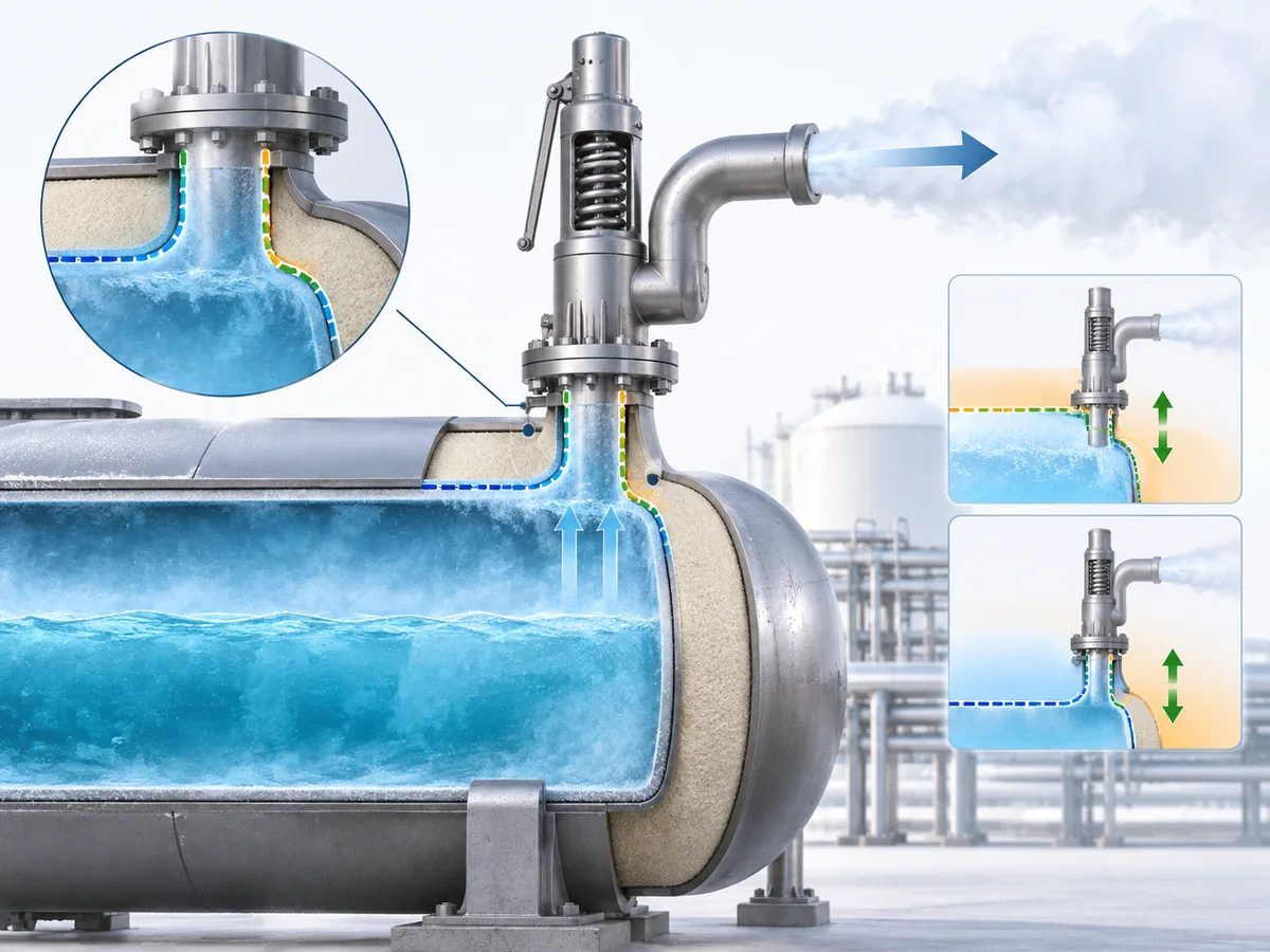
How Can Installation and Thermal Boundaries Change the Bonnet Decision?
A cryogenic safety valve does not operate as an isolated datasheet item. Its installed position affects
what becomes cold, where moisture may accumulate or freeze, how the discharge is arranged, how piping
loads reach the valve, and whether the supplier’s qualified installation conditions are being followed.
The first warning against generic rules is orientation.
Parker Bestobell’s installation instructions
for one cryogenic pressure-relief-valve design require installation and piping conditions to follow the
manufacturer’s specified orientation, drainage, venting, flow direction, support, and stress limits.
That is a model-specific requirement, not a universal installation rule for every cryogenic PRV.
By contrast,
HEROSE’s cryogenic safety-valve documentation
permits horizontal installation for the applicable Type 06002 model.
These instructions are not contradictory. They apply to different products.
They demonstrate why installation requirements should be taken from the exact configured valve,
not from an industry-wide assumption.
The same principle applies to the thermal boundary.
A valve located outside insulation, partly within an insulated process system, or associated with
a cold-box interface may expose its upper assembly differently. The engineer therefore needs to understand
where the cold zone actually lies in the proposed installation.
This does not justify generic statements such as:
- cold-box service always requires an extended bonnet;
- the bonnet must extend a fixed distance above insulation;
- LNG requires a universal bonnet length.
No universal pressure-relief-valve basis should be assumed for those statements without an applicable
project specification, manufacturer requirement, or other authoritative design basis.
Instead, check:
- where the insulation or cold boundary terminates;
- which parts of the proposed valve are exposed to that zone;
- what installation orientation the exact model permits;
- whether inlet piping imposes excessive pressure loss or mechanical loading;
- whether outlet resistance creates unacceptable built-up back pressure;
- whether moisture or ice can obstruct an outlet, drain path, pilot path, or moving component;
- whether discharge reaction forces and piping support have been addressed where applicable;
- whether the supplier’s drawing matches the actual installation;
- whether any required low-temperature test evidence applies to the proposed configuration.
For the wider system-level questions—relieving phase, discharge arrangement, cold-box context,
application conditions, and complete RFQ data—see ZOBAI’s
LNG safety valve application guide
.
This article’s narrower point is that installation can change the bonnet decision, but it
does not create a new universal bonnet rule.
What Should Be Verified Before Approving the Bonnet Configuration?
The most reliable way to close the extended-bonnet versus standard-bonnet question is to divide
the task clearly:
Define the actual duty
The buyer or responsible engineer should provide enough information to describe what the valve is
expected to relieve, what pressure sequence it must protect against, and what environment it will see.
- Fluid or composition — because “cryogenic” is not a universal compatibility category.
- Relieving phase or state — gas, vapor, liquid, or another applicable condition.
- Relieving temperature — relevant to the actual relief event.
- Normal operating temperature — particularly where the valve remains cold in normal service.
-
Set pressure and protected-equipment pressure basis — needed to establish when the valve
must respond and how it relates to the protected equipment’s allowable pressure basis. -
Allowable overpressure / accumulation basis — taken from the applicable code, service,
and relief scenario rather than assumed from a generic percentage. -
Required relieving duty or capacity — so bonnet selection and connection size do not
substitute for capacity verification. -
Back pressure and discharge-system basis — because it can create a separate
conventional/bellows/pilot and installation question. - Installation orientation, inlet piping, outlet routing, support, and drainage.
- Insulation or cold-box interface — where it affects temperature exposure.
- Applicable project code, certification, inspection, test, and document requirements.
Require evidence for the exact offered valve
A supplier response should identify more than a generic “cryogenic safety valve.”
- exact model and configuration;
- sectional or general-arrangement drawing showing the bonnet construction;
- applicable minimum and maximum temperatures;
- body and bonnet materials;
- trim materials;
- spring construction where relevant;
- seat and seal materials;
- applicable medium/service limits;
- permitted installation orientation;
- orifice / capacity identification and applicable capacity evidence;
- allowable back-pressure limits for the selected construction;
- seat-tightness acceptance basis where leakage is project-critical;
- required test and conformity documentation;
- project-specific cryogenic qualification evidence where the acceptance basis requires it.
Use standards for the question they actually answer
| Standard / code direction | Useful role in this review | What it should not be used to assume |
|---|---|---|
| ISO 21013-1 | Cryogenic pressure-relief-valve design, manufacture, and testing within its defined scope. | A universal extended-bonnet requirement or required relief capacity for every cryogenic system. |
| ISO 4126-1 | General safety-valve product requirements. | That a product standard alone establishes application suitability. |
| API 520 Part I | Sizing and selection direction for applicable refinery, chemical, and related pressure-relief applications. | That connection size or bonnet style establishes relieving capacity. |
| API 520 Part II | Installation review, including the pressure-relief device’s interaction with inlet and discharge systems. | That a valve can be evaluated independently of piping and back pressure. |
| API 527 | Seat-tightness test basis where the standard is applicable and specified. | Complete cryogenic application qualification. |
| API RP 576 | Inspection and repair practice for applicable pressure-relieving devices. | A universal inspection interval for every jurisdiction and service. |
| ASME BPVC / applicable jurisdiction | Code basis for overpressure protection, certification, and protected-equipment requirements where the project is within ASME scope. | That every international cryogenic project uses the same ASME acceptance route. |
The applicable editions, jurisdictional rules, purchaser specification, and equipment code should be
identified for the actual project. Standards should clarify responsibilities—not be stacked into the
specification merely to make the valve appear more qualified.
Inspection, recalibration, and repair remain part of lifecycle suitability
A bonnet configuration that was correct at purchase does not remove the need for inspection and testing
in service. Inspection frequency should follow the service severity, valve history, manufacturer guidance,
applicable code, owner/user program, and jurisdiction rather than an invented universal annual interval.
After disassembly, adjustment, seat work, spring work, or another repair that can affect valve function,
the applicable setting, testing, sealing, documentation, and authorization requirements need to be restored
before the valve returns to service. Where National Board / NBIC “VR” requirements apply to the valve and
jurisdiction, the repair route should follow that authorized program; this is not a universal requirement
for every valve or every country.
The final question is then simple:
If it does, the bonnet configuration can continue through project review.
If it does not, identify the unresolved issue before changing the design. The missing evidence may
concern thermal exposure, material, seat or seal, set pressure basis, back pressure, installation,
capacity, inspection status, or project documentation. An extended bonnet is only one possible configuration response.
That produces a more reliable RFQ than specifying
“cryogenic safety valve with extended bonnet”
and assuming the phrase proves suitability.
Have a cryogenic relief duty to review?
Send the medium, relieving phase, set pressure, operating and relieving temperatures,
required capacity, back pressure, installation arrangement, material requirements,
and project document requirements. The bonnet configuration can then be reviewed as part
of the complete safety-valve selection rather than as a stand-alone feature.
FAQ: Cryogenic Safety Valve Bonnet Selection
Does every cryogenic safety valve require an extended bonnet?
No. Cryogenic service alone does not create a universal extended-bonnet requirement. The exact valve
configuration, temperature exposure, materials, seat/seal system, installation, manufacturer limits,
project specification, and applicable code determine whether an extended bonnet is necessary.
When can a standard or closed bonnet be acceptable in cryogenic service?
A standard, conventional, or closed-bonnet design can remain a candidate when the exact model has
documented suitability for the required temperature, medium, phase, materials, seat/seal construction,
spring configuration, orientation, capacity, and project acceptance basis. One manufacturer’s qualified
closed-bonnet cryogenic valve does not qualify a visually similar valve from another product family.
How do set pressure, overpressure, accumulation, and blowdown affect bonnet selection?
They do not directly determine bonnet length, but they define how the pressure-relief valve must perform.
Set pressure defines the specified opening point; overpressure is the pressure increase above set pressure
during relief; accumulation relates the event to the protected equipment’s allowable pressure basis; and
blowdown describes the pressure reduction before reseating. Bonnet selection must fit within that complete
pressure-protection basis rather than being treated as a separate cosmetic choice.
How does back pressure affect a cryogenic safety valve?
Back pressure is a separate selection and installation variable. Depending on the design, it can affect
conventional spring-loaded valve opening behavior, available capacity, stability, and reseating. The
discharge system should therefore be reviewed independently of bonnet configuration, and balanced-bellows
or pilot-operated architectures should be considered only when the complete service conditions justify them.
Why is certified relieving capacity more important than connection size?
Connection size does not prove how much flow the selected pressure-relief valve can discharge under the
applicable relieving conditions. A valve can have the expected flange size and correct set pressure yet
still be undersized. Required relieving load must be compared with applicable certified or accepted
capacity data for the exact orifice and configuration.
Which standards are relevant when selecting a cryogenic safety valve?
The answer depends on project scope. ISO 21013-1 is directly relevant to cryogenic pressure-relief valves
within its defined scope; ISO 4126-1 addresses general safety-valve product requirements; API 520 Part I
and Part II cover sizing/selection and installation for their applicable industries; API 527 addresses
seat tightness where specified; and API RP 576 provides inspection and repair guidance. ASME BPVC,
National Board/NBIC, purchaser specifications, and local regulations apply where required by the project
and jurisdiction.
How often should a cryogenic safety valve be inspected or recertified?
There is no single inspection interval that is correct for every cryogenic safety valve. Frequency depends
on service severity, corrosion or fouling tendency, operating history, leakage, cycling, manufacturer
instructions, owner/user inspection program, applicable code, and jurisdiction. After repair or adjustment,
the valve should be tested, documented, sealed, and returned to service in accordance with the applicable
repair and regulatory basis.