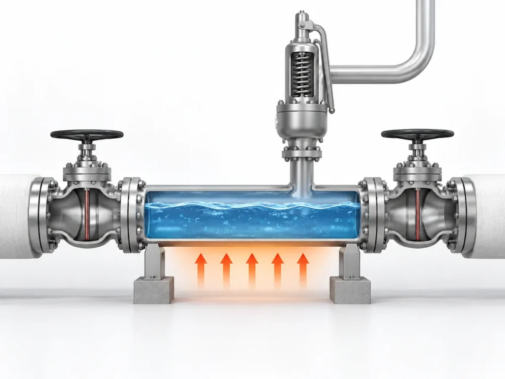
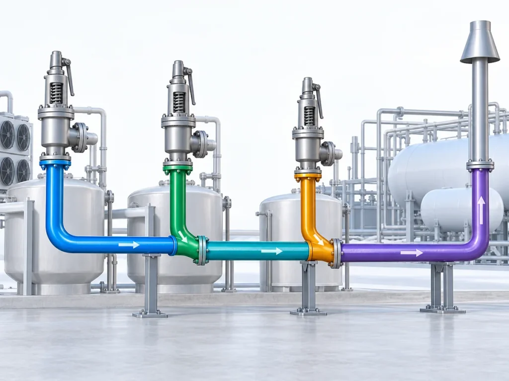
Learn when external fire becomes a pressure-vessel relief scenario, what controls the relieving load, and how the result feeds into PSV sizing.


External fire should not be treated as a shortcut from “pressure vessel” to “larger safety valve.” It is first a relief-scenario question. The engineer has to establish that a credible fire can expose the protected vessel, determine how that exposure affects the vessel inventory, calculate the resulting required relieving load under the applicable design basis, and only then size and verify the pressure-relief device.
That sequence matters because several different engineering responsibilities are easy to collapse into one. A vessel’s size is not its required relieving capacity. Set pressure is not relieving capacity. A valve connection size is not proof of flow capacity. And a pressure-relief device that can pass the calculated fire load does not, by itself, prove that the vessel will remain mechanically sound throughout a severe fire.
For a typical liquid-containing vessel exposed to a credible pool fire, the engineering chain is broadly:
credible fire exposure → heat input to the vessel and liquid inventory → fluid response and vapor generation → required relieving load → PSV sizing and capacity verification → inlet, outlet and disposal-system checks.
That chain is useful, but it is not universal. Gas-only, largely unwetted, supercritical, reactive, multicomponent or potentially two-phase systems may require a different analytical treatment. The first task is therefore to identify which fire scenario and response model actually apply.
When External Fire Becomes a Governing Relief Scenario
External fire is a recognized cause of overpressure in API 521 pressure-relief systems, but the existence of a pressure vessel does not automatically make fire the governing case. The scenario has to be credible for the actual installation.
That credibility assessment starts with the protected equipment rather than the relief valve. An engineer should establish where the vessel is located, what credible fire source could expose it, whether a sustained pool or other relevant fire exposure is plausible, what inventory may be present, and what project or code basis governs the assessment. Layout, drainage, fire protection and other safeguards may influence that assessment, but they should not be treated as automatic reasons to remove the fire case.
In broader pressure vessel safety valve applications, the same vessel may also have other overpressure scenarios—such as blocked outlet, utility failure, control-valve failure, exchanger tube rupture or thermal expansion. Fire is therefore one candidate scenario in the overall relief basis. The design process identifies the credible scenarios, calculates the required load for each one using an appropriate method, and then establishes which case governs the pressure-relief requirement.
This distinction prevents a common sizing error: starting with a familiar “fire-case” valve size before the actual fire case has been defined. The valve is downstream of the scenario analysis. It cannot establish the scenario for the engineer.
Why Fire Exposure Creates a Relief Load Inside a Pressure Vessel
For an applicable liquid-containing vessel, the classic external-fire case begins with heat entering the vessel through the fire-exposed, liquid-wetted wall. The contained liquid absorbs that energy. As the inventory heats under pressure, vapor generation can increase and create the relieving demand that the pressure-relief system has to handle.
The important point is that the relief demand is created by the interaction between the fire and the process inventory. “External fire” is therefore not simply an external-temperature specification for the valve. It changes the energy balance of the protected system.
For a simple liquid-vaporization case, the calculation concept is straightforward. An applicable fire method is used to establish the absorbed heat input. The thermodynamic condition of the fluid at the relieving state is then used to determine how that heat input translates into vapor generation. The result is a required relieving rate—not a valve model and not a connection size.
The liquid-vaporization path has limits
That reasoning should not be transferred unchanged to every vessel.
If the vessel contains little or no liquid, the fire may heat a largely unwetted metal wall and a gas or vapor inventory. A supercritical fluid does not behave as a conventional boiling liquid. Multicomponent mixtures can change composition as material vaporizes. Some systems may develop two-phase discharge. Reactive service can introduce additional heat-generation mechanisms.
These cases may require a more detailed transient mass-and-energy analysis rather than a simple liquid-vaporization approximation.
There is also a separate mechanical-integrity issue. A pressure-relief device limits pressure by removing mass from the protected system, but it does not cool every part of the vessel wall equally. An unwetted wall exposed to severe fire can heat rapidly and lose strength. In some cases, emergency depressuring, thermal-response analysis or other fire-protection measures may therefore matter even when the relief device has adequate flow capacity.
The practical implication is that the engineer should identify the inventory and response mode before choosing the fire calculation method:
- liquid-containing and suitably represented by an empirical pool-fire method;
- gas or vapor dominated;
- supercritical;
- multicomponent or potentially two-phase;
- reactive or otherwise outside the simple vaporization model.
The calculation should follow that physical identity, not the convenience of a familiar equation.
Image placeholder: Future approved visual may be added later.
Purpose: Compare the liquid-containing wetted-wall fire-response path with non-simple gas, vapor, unwetted, supercritical or complex-phase paths without adding new claims.
Which Inputs Control the Fire-Case Relief Requirement
A credible fire case can still be calculated incorrectly if the input data do not describe the actual vessel and relieving condition. The following inputs are not a generic checklist to fill mechanically; each one matters because it can change a specific part of the engineering chain.
| Input | Why it matters to the fire case | What must be established |
|---|---|---|
| Protected vessel and fire exposure | Defines whether the scenario is credible and what part of the equipment is exposed | Vessel identity, location, credible fire source and applicable fire basis |
| Inventory and liquid level | Can change the wetted area, heat absorption and possible discharge behavior | Credible inventory and liquid level for the relief scenario |
| Fluid composition and phase | Determines how absorbed heat becomes pressure rise or vapor generation | Liquid, vapor, gas, supercritical, multicomponent, reactive or possible two-phase behavior |
| Operating pressure and MAWP/design basis | Establishes the normal and protected pressure context | Correct project definitions rather than interchangeable pressure terms |
| Set-pressure basis | Influences the pressure at which the relief device begins to act | Project/code basis and selected protection philosophy |
| Relieving pressure and temperature | Control fluid properties and the sizing condition | Values derived from the governing design basis |
| Wetted/exposed area basis | Influences empirical fire heat input for applicable liquid cases | Geometry and liquid-wetted portion allowed by the governing method |
| Environmental or mitigation assumptions | Can change assumed heat input if credit is legitimately permitted | Actual insulation, fireproofing, drainage or other condition and whether the governing method permits credit |
| Back pressure and discharge arrangement | Can affect final device capacity and system performance | Downstream pressure, piping and disposal-system basis |
The table is useful because it shows why “vessel diameter,” “valve size” or “set pressure” cannot replace the full fire-case definition.
Wetted area is a calculation input, not a valve-sizing shortcut
In API Std 521’s empirical pool-fire approach, absorbed fire heat is related to the applicable wetted surface area and an environmental factor. The relationship uses a wetted-area exponent of 0.82.
That does not mean wetted area alone determines the required PSV size. It establishes part of the heat-input calculation. The resulting heat must still be translated into a relieving load using the relevant thermodynamic state, and the calculated relieving load must then be passed into the separate pressure-relief-device sizing process.
The exact coefficient, environmental factor and permitted treatment of insulation or other mitigation measures must follow the governing standard edition and project basis. They should not be treated as universal constants detached from their application conditions.
Mitigation credit must be defensible
Insulation, fireproofing, drainage or firefighting systems can materially affect a fire analysis, but using them as a calculation credit is an engineering decision, not an automatic reduction.
For example, insulation can only reduce the assumed heat input if the calculation method permits that treatment and the insulation can reasonably be expected to remain effective under the relevant fire exposure. The same logic applies to drainage and other mitigation measures: the engineer should establish that the credited condition is real, applicable and consistent with the project’s governing basis.
A calculation that depends on an optimistic mitigation assumption can understate the required relief load if that assumption does not hold during the event.
From Fire Exposure to Required Relieving Rate: The Calculation Logic
The purpose of the fire calculation is to convert a credible scenario into a required relieving load that can be used by the pressure-relief-device sizing process.
For an applicable liquid-containing case, the reasoning can be followed in four engineering moves.
First, establish the credible fire exposure and the wetted surface basis permitted by the governing method. This determines the geometric part of the heat-input calculation.
Second, determine the absorbed fire heat under the applicable environmental and mitigation assumptions. API Std 521’s empirical pool-fire method expresses this heat-input relationship as proportional to an environmental factor multiplied by wetted area raised to the 0.82 power. The exact coefficient and project inputs must be taken from the governing current design basis rather than remembered or generalized.
Third, establish the fluid state at the relieving condition. Relieving pressure and temperature matter because thermodynamic properties change with state. Operating pressure, MAWP or design pressure, set pressure, overpressure, accumulation and relieving pressure describe different aspects of the protection problem; they should not be used as synonyms.
Fourth, translate the absorbed heat into the required relieving rate using the thermodynamic method appropriate to the inventory.
For a simple liquid-vaporization case where the approximation is valid, the engineering relationship can be expressed conceptually as:
required vapor-generation rate ≈ absorbed fire heat ÷ latent heat at the relevant relieving state.
That expression is a useful explanation of the physical mechanism, but it is not a universal fire-relief formula. Multicomponent fluids can change composition as they vaporize. Two-phase flow may occur in some systems. Gas, vapor or supercritical inventories require a different treatment. Reactive systems may introduce additional energy. The method must therefore match the real fluid response.
Representative engineering scenario
Consider an illustrative process vessel that normally contains a partial liquid inventory and is located where a sustained external pool fire is considered credible.
The engineering team would not begin by selecting a nominal PSV connection. It would first establish the fire-exposed vessel geometry and the credible liquid level. Those two items determine the applicable wetted-area basis. The team would then establish the fire heat input using the governing method and justified environmental assumptions.
Next, the relieving condition and fluid properties would be defined. The calculated heat input would be translated into the required vapor-generation rate using the thermodynamic method appropriate to that fluid. That required rate would then become an input to the separate PSV sizing and capacity-verification process.
If the same vessel instead had only a small liquid inventory and a large unwetted vapor space, the same calculation should not simply be reused without review. The dominant concern could shift toward gas heating, vessel-wall temperature, thermal weakening or depressuring behavior. The physical response has changed, so the engineering method may need to change with it.
This is why the fire scenario must remain connected to the actual inventory throughout the analysis.
Image placeholder: Future approved visual may be added later.
Purpose: Explain the handoff from external-fire scenario analysis to required relieving load, PSV sizing, documented capacity verification and relief-system checks without adding new claims.
How the Fire-Case Relief Basis Affects PSV Sizing and System Checks
Once the external-fire analysis produces a required relieving rate, the process-side scenario calculation has done its main job. It has established the demand that the pressure-relief system must handle.
It has not yet proved that a particular valve is suitable.
The next stage is device sizing and capacity verification; the broader method belongs to the safety valve sizing and certified relieving capacity guide. The required relieving rate, relieving pressure, relieving temperature, fluid phase and other applicable properties are used to determine the required flow area under the relevant sizing method. A valve or orifice can then be selected, but its manufacturer-documented or certified capacity must be adequate for the required load under the applicable capacity basis.
These quantities must remain distinct:
required relieving rate ≠ required flow area ≠ selected orifice ≠ nominal connection size ≠ documented or certified capacity.
A valve can have the same inlet connection as another valve and still have a different flow area or capacity. Two valves can have the same set pressure and still have different capacity or back-pressure behavior. A familiar orifice designation should not be treated as proof of capacity outside the applicable manufacturer or certification basis.
The valve is also part of a piping system
Capacity verification does not end at the valve nozzle.
A large external-fire load can place significant demand on the inlet line, outlet line and disposal system. Inlet pressure loss can affect valve performance. Built-up or superimposed back pressure can change the effective operating conditions at the valve. A common relief header may have to handle simultaneous loads if one fire affects several pieces of equipment. Outlet piping, flare or vent-system resistance and the final discharge location must also be consistent with the selected pressure-relief device.
That does not mean this article should become a complete flare-network or back-pressure design guide. The important boundary is simpler: the fire-case load must be carried forward into system verification rather than treated as finished once a valve capacity number has been found.
The fire scenario also does not automatically select a conventional spring-loaded, balanced bellows or pilot-operated configuration. Configuration depends on the actual back pressure, service condition, pressure and temperature, stability requirements, installation and manufacturer limitations. “Fire service” alone is not a valve-configuration decision.
What Must Be Confirmed Before the Fire Case Is Accepted for Design
A useful external-fire analysis should leave a traceable design basis. Before the result is used to select or specify a pressure-relief device, the engineer should be able to answer the following questions.
- What exactly is being protected? Identify the vessel and the relevant design or MAWP basis.
- Why is external fire credible? Define the fire source, equipment exposure and project assumptions.
- What inventory is present? Establish liquid level, fluid composition and phase behavior relevant to the event.
- Which fire method applies? Confirm whether the empirical liquid pool-fire approach is appropriate or whether a different analytical treatment is required.
- What pressure and temperature define the relieving state? Keep operating pressure, set pressure, overpressure/accumulation basis and relieving pressure distinct.
- How was heat input established? Record the wetted/exposed area basis and any environmental, insulation, drainage or other mitigation assumptions.
- How was the required relieving rate calculated? Preserve the thermodynamic basis, including important phase or composition limitations.
- Which standard and edition govern the calculation? Confirm the actual project requirement rather than assuming that every referenced standard is simultaneously applicable.
- Can the selected device demonstrate enough capacity? Use the applicable manufacturer and certification/documentation basis for the selected valve and orifice.
- Can the connected relief system handle the flow? Check inlet losses, back pressure, outlet piping and the disposal system as applicable.
If any of these items is unknown, the uncertainty should remain visible in the engineering review. A missing input should not be replaced by a nominal valve size, a catalogue maximum or a familiar rule of thumb.
Engineering next step
For an engineering review of an external-fire case, prepare the protected-equipment data, credible fire scenario, process medium and phase, vessel inventory or liquid level, operating and design/MAWP information, set-pressure basis, relieving conditions, fire-exposure assumptions, required relieving load or calculation basis if already available, and the relevant downstream back-pressure or discharge-system information.
That information allows the conversation to begin with the real protection problem rather than with a guessed valve size.
Request an Engineering Review
To review an external-fire relief case, provide the protected vessel and credible fire scenario, process medium and phase, vessel inventory or liquid level, operating and design/MAWP information, set-pressure basis, relieving conditions, fire-exposure assumptions, required relieving load or calculation basis if available, and relevant back-pressure or discharge-system information. Valve capacity, configuration and final suitability should be confirmed against the selected product data, governing standard and project requirements.
Request an Engineering Review