Scopri quando un incendio esterno diventa uno scenario di sfioro per un recipiente in pressione, quali fattori determinano il carico di scarico e come il risultato confluisce nel dimensionamento della PSV.


L'incendio esterno non deve essere trattato come una scorciatoia da “recipiente in pressione” a “valvola di sicurezza più grande”. È innanzitutto una questione di scenario di sfioro. L'ingegnere deve stabilire che un incendio credibile possa esporre il recipiente protetto, determinare come tale esposizione influenzi il contenuto del recipiente, calcolare il carico di scarico richiesto risultante secondo la base di progetto applicabile e solo successivamente dimensionare e verificare il dispositivo di protezione contro la sovrapressione.
Questa sequenza è importante perché diverse responsabilità ingegneristiche vengono facilmente confuse in una sola. La dimensione di un recipiente non è la sua capacità di scarico richiesta. La pressione di taratura non è la capacità di scarico. La dimensione della connessione di una valvola non è prova della capacità di flusso. E un dispositivo di protezione contro la sovrapressione in grado di smaltire il carico di incendio calcolato non dimostra, di per sé, che il recipiente rimarrà meccanicamente integro durante un incendio severo.
Per un tipico recipiente contenente liquido esposto a un incendio di pozza credibile, la catena ingegneristica è in linea di massima:
esposizione credibile all'incendio → apporto termico al recipiente e al contenuto liquido → risposta del fluido e generazione di vapore → carico di scarico richiesto → dimensionamento e verifica della capacità della PSV → verifiche su ingresso, uscita e sistema di smaltimento.
Questa catena è utile, ma non universale. Sistemi solo gassosi, in gran parte non bagnati, supercritici, reattivi, multicomponente o potenzialmente bifase possono richiedere un trattamento analitico diverso. Il primo compito è quindi identificare quale scenario di incendio e modello di risposta si applicano effettivamente.
Quando l'incendio esterno diventa uno scenario di sfioro dominante
L'incendio esterno è una causa riconosciuta di sovrapressione in Sistemi di sfioro pressione API 521, ma l'esistenza di un recipiente in pressione non rende automaticamente l'incendio il caso dominante. Lo scenario deve essere credibile per l'installazione effettiva.
Questa valutazione di credibilità parte dall'apparecchiatura protetta, non dalla valvola di sicurezza. L'ingegnere deve stabilire dove si trova il recipiente, quale fonte di incendio credibile potrebbe esporlo, se un incendio di pozza sostenuto o un'altra esposizione rilevante sia plausibile, quale contenuto possa essere presente e quale base di progetto o normativa governi la valutazione. Layout, drenaggio, protezione antincendio e altre misure di salvaguardia possono influenzare tale valutazione, ma non devono essere considerati motivi automatici per eliminare il caso incendio.
In ambito più ampio applicazioni delle valvole di sicurezza per recipienti in pressione, lo stesso recipiente può presentare anche altri scenari di sovrapressione—come ostruzione dell'uscita, guasto delle utenze, guasto della valvola di regolazione, rottura dei tubi dello scambiatore o dilatazione termica. L'incendio è quindi uno scenario candidato nell'ambito della base di sfioro complessiva. Il processo di progettazione identifica gli scenari credibili, calcola il carico richiesto per ciascuno con un metodo appropriato e stabilisce poi quale caso governa il requisito di protezione contro la sovrapressione.
Questa distinzione evita un errore di dimensionamento comune: partire da una dimensione familiare di valvola per “caso incendio” prima che il caso incendio effettivo sia stato definito. La valvola è a valle dell'analisi dello scenario. Non può stabilire lo scenario per l'ingegnere.
Perché l'esposizione al fuoco genera un carico di sfioro all'interno di un recipiente in pressione
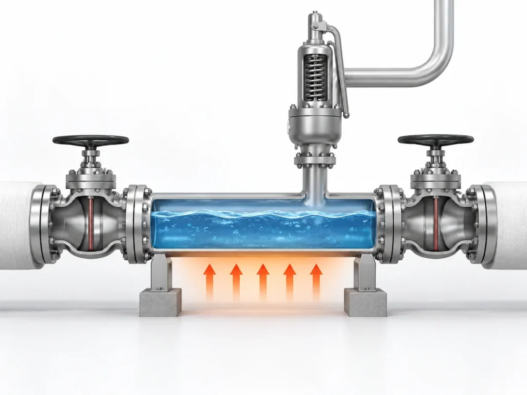
Per un recipiente idoneo contenente liquido, il classico caso di incendio esterno inizia con il calore che entra nel recipiente attraverso la parete bagnata dal liquido ed esposta al fuoco. Il liquido contenuto assorbe tale energia. Con il riscaldamento del contenuto sotto pressione, la generazione di vapore può aumentare e creare la richiesta di sfioro che il sistema di protezione contro la sovrapressione deve gestire.
Il punto importante è che la richiesta di sfioro è creata dall'interazione tra l'incendio e il contenuto di processo. L“”incendio esterno" non è quindi semplicemente una specifica di temperatura esterna per la valvola. Esso modifica il bilancio energetico del sistema protetto.
Per un semplice caso di vaporizzazione di liquido, il concetto di calcolo è diretto. Si utilizza un metodo applicabile per l'incendio per determinare l'apporto di calore assorbito. La condizione termodinamica del fluido allo stato di sfioro viene quindi utilizzata per determinare come tale apporto di calore si traduce in generazione di vapore. Il risultato è una portata di sfioro richiesta, non un modello di valvola e non una dimensione di connessione.
Il percorso di vaporizzazione del liquido ha dei limiti
Tale ragionamento non deve essere trasferito invariato a ogni recipiente.
Se il recipiente contiene poco o nessun liquido, l'incendio può riscaldare una parete metallica in gran parte non bagnata e un contenuto di gas o vapore. Un fluido supercritico non si comporta come un liquido in ebollizione convenzionale. Le miscele multicomponente possono cambiare composizione man mano che il materiale vaporizza. Alcuni sistemi possono sviluppare uno scarico bifase. Il servizio reattivo può introdurre ulteriori meccanismi di generazione di calore.
Questi casi possono richiedere un'analisi transitoria più dettagliata di massa ed energia anziché una semplice approssimazione di vaporizzazione del liquido.
Esiste anche una questione separata di integrità meccanica. Un dispositivo di protezione contro la sovrapressione limita la pressione rimuovendo massa dal sistema protetto, ma non raffredda uniformemente ogni parte della parete del recipiente. Una parete non bagnata esposta a un incendio severo può riscaldarsi rapidamente e perdere resistenza. In alcuni casi, la depressurizzazione di emergenza, l'analisi della risposta termica o altre misure di protezione antincendio possono quindi essere importanti anche quando il dispositivo di sfioro ha una capacità di flusso adeguata.
L'implicazione pratica è che l'ingegnere dovrebbe identificare il contenuto e la modalità di risposta prima di scegliere il metodo di calcolo per l'incendio:
- contenente liquido e adeguatamente rappresentato da un metodo empirico per incendio di pozza;
- dominato da gas o vapore;
- supercritico;
- multicomponente o potenzialmente bifase;
- reattivo o comunque al di fuori del semplice modello di vaporizzazione.
Il calcolo deve seguire tale identità fisica, non la comodità di un'equazione familiare.
Segnaposto immagine: Una visuale approvata potrà essere aggiunta in seguito.
Scopo: Confrontare il percorso di risposta all'incendio con parete bagnata contenente liquido con i percorsi non semplici per gas, vapore, parete non bagnata, supercritici o a fasi complesse, senza aggiungere nuove affermazioni.
Quali dati di ingresso controllano il requisito di sfioro nello scenario incendio
Un caso incendio credibile può comunque essere calcolato in modo errato se i dati di ingresso non descrivono il recipiente e la condizione di sfioro effettivi. I seguenti dati di ingresso non sono una lista di controllo generica da compilare meccanicamente; ciascuno è importante perché può modificare una parte specifica della catena ingegneristica.
| Ingresso | Perché è importante per il caso incendio | Cosa deve essere stabilito |
|---|---|---|
| Recipiente protetto ed esposizione al fuoco | Definisce se lo scenario è credibile e quale parte dell'apparecchiatura è esposta | Identità del recipiente, ubicazione, fonte di incendio credibile e base antincendio applicabile |
| Inventario e livello del liquido | Può modificare l'area bagnata, l'assorbimento di calore e il possibile comportamento allo scarico | Inventario e livello del liquido credibili per lo scenario di sfioro |
| Composizione e fase del fluido | Determina come il calore assorbito si traduce in aumento di pressione o generazione di vapore | Comportamento liquido, vapore, gas, supercritico, multicomponente, reattivo o possibile bifase |
| Pressione di esercizio e MAWP/base di progetto | Stabilisce il contesto di pressione normale e protetta | Definizioni di progetto corrette anziché termini di pressione intercambiabili |
| Base della pressione di taratura | Influences the pressure at which the relief device begins to act | Project/code basis and selected protection philosophy |
| Pressione e temperatura di scarico | Control fluid properties and the sizing condition | Values derived from the governing design basis |
| Wetted/exposed area basis | Influences empirical fire heat input for applicable liquid cases | Geometry and liquid-wetted portion allowed by the governing method |
| Environmental or mitigation assumptions | Can change assumed heat input if credit is legitimately permitted | Actual insulation, fireproofing, drainage or other condition and whether the governing method permits credit |
| Contropressione e disposizione di scarico | Can affect final device capacity and system performance | Downstream pressure, piping and disposal-system basis |
The table is useful because it shows why “vessel diameter,” “valve size” or “set pressure” cannot replace the full fire-case definition.
Wetted area is a calculation input, not a valve-sizing shortcut
In API Std 521’s empirical pool-fire approach, absorbed fire heat is related to the applicable wetted surface area and an environmental factor. The relationship uses a wetted-area exponent of 0.82.
That does not mean wetted area alone determines the required PSV size. It establishes part of the heat-input calculation. The resulting heat must still be translated into a relieving load using the relevant thermodynamic state, and the calculated relieving load must then be passed into the separate pressure-relief-device sizing process.
The exact coefficient, environmental factor and permitted treatment of insulation or other mitigation measures must follow the governing standard edition and project basis. They should not be treated as universal constants detached from their application conditions.
Mitigation credit must be defensible
Insulation, fireproofing, drainage or firefighting systems can materially affect a fire analysis, but using them as a calculation credit is an engineering decision, not an automatic reduction.
For example, insulation can only reduce the assumed heat input if the calculation method permits that treatment and the insulation can reasonably be expected to remain effective under the relevant fire exposure. The same logic applies to drainage and other mitigation measures: the engineer should establish that the credited condition is real, applicable and consistent with the project’s governing basis.
A calculation that depends on an optimistic mitigation assumption can understate the required relief load if that assumption does not hold during the event.
From Fire Exposure to Required Relieving Rate: The Calculation Logic
The purpose of the fire calculation is to convert a credible scenario into a required relieving load that can be used by the pressure-relief-device sizing process.
For an applicable liquid-containing case, the reasoning can be followed in four engineering moves.
First, establish the credible fire exposure and the wetted surface basis permitted by the governing method. This determines the geometric part of the heat-input calculation.
Second, determine the absorbed fire heat under the applicable environmental and mitigation assumptions. API Std 521’s empirical pool-fire method expresses this heat-input relationship as proportional to an environmental factor multiplied by wetted area raised to the 0.82 power. The exact coefficient and project inputs must be taken from the governing current design basis rather than remembered or generalized.
Third, establish the fluid state at the relieving condition. Relieving pressure and temperature matter because thermodynamic properties change with state. Operating pressure, MAWP or design pressure, set pressure, overpressure, accumulation and relieving pressure describe different aspects of the protection problem; they should not be used as synonyms.
Fourth, translate the absorbed heat into the required relieving rate using the thermodynamic method appropriate to the inventory.
For a simple liquid-vaporization case where the approximation is valid, the engineering relationship can be expressed conceptually as:
required vapor-generation rate ≈ absorbed fire heat ÷ latent heat at the relevant relieving state.
That expression is a useful explanation of the physical mechanism, but it is not a universal fire-relief formula. Multicomponent fluids can change composition as they vaporize. Two-phase flow may occur in some systems. Gas, vapor or supercritical inventories require a different treatment. Reactive systems may introduce additional energy. The method must therefore match the real fluid response.
Representative engineering scenario
Consider an illustrative process vessel that normally contains a partial liquid inventory and is located where a sustained external pool fire is considered credible.
The engineering team would not begin by selecting a nominal PSV connection. It would first establish the fire-exposed vessel geometry and the credible liquid level. Those two items determine the applicable wetted-area basis. The team would then establish the fire heat input using the governing method and justified environmental assumptions.
Next, the relieving condition and fluid properties would be defined. The calculated heat input would be translated into the required vapor-generation rate using the thermodynamic method appropriate to that fluid. That required rate would then become an input to the separate PSV sizing and capacity-verification process.
If the same vessel instead had only a small liquid inventory and a large unwetted vapor space, the same calculation should not simply be reused without review. The dominant concern could shift toward gas heating, vessel-wall temperature, thermal weakening or depressuring behavior. The physical response has changed, so the engineering method may need to change with it.
This is why the fire scenario must remain connected to the actual inventory throughout the analysis.
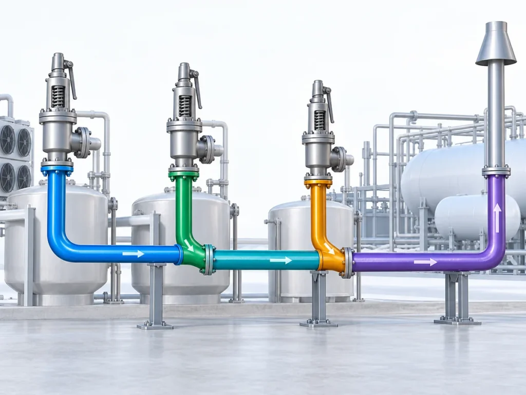
Segnaposto immagine: Una visuale approvata potrà essere aggiunta in seguito.
Scopo: Explain the handoff from external-fire scenario analysis to required relieving load, PSV sizing, documented capacity verification and relief-system checks without adding new claims.
How the Fire-Case Relief Basis Affects PSV Sizing and System Checks
Once the external-fire analysis produces a required relieving rate, the process-side scenario calculation has done its main job. It has established the demand that the pressure-relief system must handle.
It has not yet proved that a particular valve is suitable.
The next stage is device sizing and capacity verification; the broader method belongs to the dimensionamento della valvola di sicurezza e alla capacità di sfioro certificata guide. The required relieving rate, relieving pressure, relieving temperature, fluid phase and other applicable properties are used to determine the required flow area under the relevant sizing method. A valve or orifice can then be selected, but its manufacturer-documented or certified capacity must be adequate for the required load under the applicable capacity basis.
These quantities must remain distinct:
required relieving rate ≠ required flow area ≠ selected orifice ≠ nominal connection size ≠ documented or certified capacity.
A valve can have the same inlet connection as another valve and still have a different flow area or capacity. Two valves can have the same set pressure and still have different capacity or back-pressure behavior. A familiar orifice designation should not be treated as proof of capacity outside the applicable manufacturer or certification basis.
The valve is also part of a piping system
Capacity verification does not end at the valve nozzle.
A large external-fire load can place significant demand on the inlet line, outlet line and disposal system. Inlet pressure loss can affect valve performance. Built-up or superimposed back pressure can change the effective operating conditions at the valve. A common relief header may have to handle simultaneous loads if one fire affects several pieces of equipment. Outlet piping, flare or vent-system resistance and the final discharge location must also be consistent with the selected pressure-relief device.
That does not mean this article should become a complete flare-network or back-pressure design guide. The important boundary is simpler: the fire-case load must be carried forward into system verification rather than treated as finished once a valve capacity number has been found.
The fire scenario also does not automatically select a conventional spring-loaded, balanced bellows or pilot-operated configuration. Configuration depends on the actual back pressure, service condition, pressure and temperature, stability requirements, installation and manufacturer limitations. “Fire service” alone is not a valve-configuration decision.
What Must Be Confirmed Before the Fire Case Is Accepted for Design
A useful external-fire analysis should leave a traceable design basis. Before the result is used to select or specify a pressure-relief device, the engineer should be able to answer the following questions.
- What exactly is being protected? Identify the vessel and the relevant design or MAWP basis.
- Why is external fire credible? Define the fire source, equipment exposure and project assumptions.
- What inventory is present? Establish liquid level, fluid composition and phase behavior relevant to the event.
- Which fire method applies? Confirm whether the empirical liquid pool-fire approach is appropriate or whether a different analytical treatment is required.
- What pressure and temperature define the relieving state? Keep operating pressure, set pressure, overpressure/accumulation basis and relieving pressure distinct.
- How was heat input established? Record the wetted/exposed area basis and any environmental, insulation, drainage or other mitigation assumptions.
- How was the required relieving rate calculated? Preserve the thermodynamic basis, including important phase or composition limitations.
- Which standard and edition govern the calculation? Confirm the actual project requirement rather than assuming that every referenced standard is simultaneously applicable.
- Can the selected device demonstrate enough capacity? Use the applicable manufacturer and certification/documentation basis for the selected valve and orifice.
- Can the connected relief system handle the flow? Check inlet losses, back pressure, outlet piping and the disposal system as applicable.
If any of these items is unknown, the uncertainty should remain visible in the engineering review. A missing input should not be replaced by a nominal valve size, a catalogue maximum or a familiar rule of thumb.
Prossimo passo ingegneristico
For an engineering review of an external-fire case, prepare the protected-equipment data, credible fire scenario, process medium and phase, vessel inventory or liquid level, operating and design/MAWP information, set-pressure basis, relieving conditions, fire-exposure assumptions, required relieving load or calculation basis if already available, and the relevant downstream back-pressure or discharge-system information.
That information allows the conversation to begin with the real protection problem rather than with a guessed valve size.
Richiedi una revisione ingegneristica
To review an external-fire relief case, provide the protected vessel and credible fire scenario, process medium and phase, vessel inventory or liquid level, operating and design/MAWP information, set-pressure basis, relieving conditions, fire-exposure assumptions, required relieving load or calculation basis if available, and relevant back-pressure or discharge-system information. Valve capacity, configuration and final suitability should be confirmed against the selected product data, governing standard and project requirements.
Richiedi una revisione ingegneristica