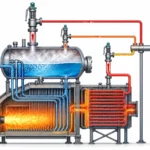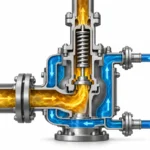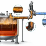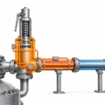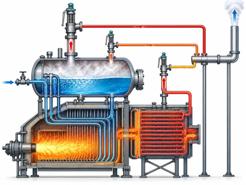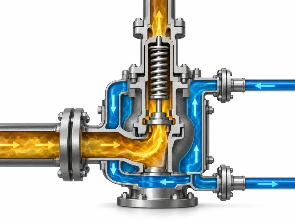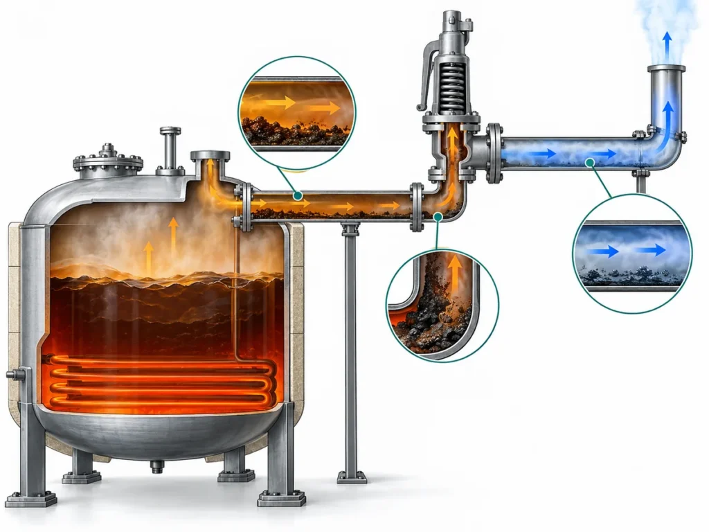
Learn when external fire becomes a pressure-vessel relief scenario, what controls the relieving load, and how the result feeds into PSV sizing.

An external fire relief scenario should not be treated as a shortcut from “pressure vessel” to “larger safety valve.” It is first a relief-scenario question. The engineer has to establish that a credible fire can expose the protected vessel, determine how that exposure affects the vessel inventory, calculate the resulting required relieving load under the applicable design basis, and only then size and verify the pressure-relief device.
That sequence matters because several different engineering responsibilities are easy to collapse into one. A vessel’s size is not its required relieving capacity. Set pressure is not relieving capacity. A valve connection size is not proof of flow capacity. And a pressure-relief device that can pass the calculated fire load does not, by itself, prove that the vessel will remain mechanically sound throughout a severe fire.
For a typical liquid-containing vessel exposed to a credible pool fire, the engineering chain is broadly:
credible fire exposure → heat input to the vessel and liquid inventory → fluid response and vapor generation → required relieving load → PSV sizing and capacity verification → inlet, outlet and disposal-system checks.
That chain is useful, but it is not universal. Gas-only, largely unwetted, supercritical, reactive, multicomponent or potentially two-phase systems may require a different analytical treatment. The first task is therefore to identify which fire scenario and response model actually apply.
External Fire Relief Scenario: When Fire Governs
External fire is a recognized cause of overpressure in API 521 压力泄放系统, but the existence of a pressure vessel does not automatically make fire the governing case. The scenario has to be credible for the actual installation.
That credibility assessment starts with the protected equipment rather than the relief valve. An engineer should establish where the vessel is located, what credible fire source could expose it, whether a sustained pool or other relevant fire exposure is plausible, what inventory may be present, and what project or code basis governs the assessment. Layout, drainage, fire protection and other safeguards may influence that assessment, but they should not be treated as automatic reasons to remove the fire case.
In broader 压力容器安全阀应用, the same vessel may also have other overpressure scenarios—such as blocked outlet, utility failure, control-valve failure, exchanger tube rupture or thermal expansion. Fire is therefore one candidate scenario in the overall relief basis. The design process identifies the credible scenarios, calculates the required load for each one using an appropriate method, and then establishes which case governs the pressure-relief requirement.
This distinction prevents a common sizing error: starting with a familiar “fire-case” valve size before the actual fire case has been defined. The valve is downstream of the scenario analysis. It cannot establish the scenario for the engineer.
Why Fire Exposure Creates a Relief Load Inside a Pressure Vessel
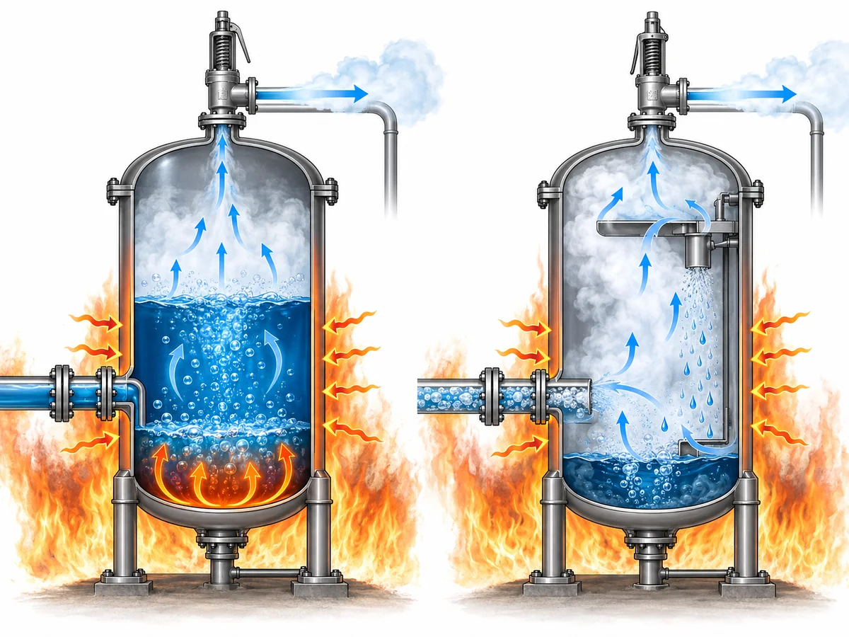
For an applicable liquid-containing vessel, the classic external-fire case begins with heat entering the vessel through the fire-exposed, liquid-wetted wall. The contained liquid absorbs that energy. As the inventory heats under pressure, vapor generation can increase and create the relieving demand that the pressure-relief system has to handle.
The important point is that the relief demand is created by the interaction between the fire and the process inventory. “External fire” is therefore not simply an external-temperature specification for the valve. It changes the energy balance of the protected system.
For a simple liquid-vaporization case, the calculation concept is straightforward. An applicable fire method is used to establish the absorbed heat input. The thermodynamic condition of the fluid at the relieving state is then used to determine how that heat input translates into vapor generation. The result is a required relieving rate—not a valve model and not a connection size.
The liquid-vaporization path has limits
That reasoning should not be transferred unchanged to every vessel.
If the vessel contains little or no liquid, the fire may heat a largely unwetted metal wall and a gas or vapor inventory. A supercritical fluid does not behave as a conventional boiling liquid. Multicomponent mixtures can change composition as material vaporizes. Some systems may develop two-phase discharge. Reactive service can introduce additional heat-generation mechanisms.
These cases may require a more detailed transient mass-and-energy analysis rather than a simple liquid-vaporization approximation.
There is also a separate mechanical-integrity issue. A pressure-relief device limits pressure by removing mass from the protected system, but it does not cool every part of the vessel wall equally. An unwetted wall exposed to severe fire can heat rapidly and lose strength. In some cases, emergency depressuring, thermal-response analysis or other fire-protection measures may therefore matter even when the relief device has adequate flow capacity.
The practical implication is that the engineer should identify the inventory and response mode before choosing the fire calculation method:
- liquid-containing and suitably represented by an empirical pool-fire method;
- gas or vapor dominated;
- supercritical;
- multicomponent or potentially two-phase;
- reactive or otherwise outside the simple vaporization model.
The calculation should follow that physical identity, not the convenience of a familiar equation.
Which Inputs Control the Fire-Case Relief Requirement
A credible fire case can still be calculated incorrectly if the input data do not describe the actual vessel and relieving condition. The following inputs are not a generic checklist to fill mechanically; each one matters because it can change a specific part of the engineering chain.
| 输入 | Why it matters to the fire case | 必须确定的内容 |
|---|---|---|
| Protected vessel and fire exposure | Defines whether the scenario is credible and what part of the equipment is exposed | Vessel identity, location, credible fire source and applicable fire basis |
| Inventory and liquid level | Can change the wetted area, heat absorption and possible discharge behavior | Credible inventory and liquid level for the relief scenario |
| 流体组成与相态 | Determines how absorbed heat becomes pressure rise or vapor generation | Liquid, vapor, gas, supercritical, multicomponent, reactive or possible two-phase behavior |
| Operating pressure and MAWP/design basis | Establishes the normal and protected pressure context | Correct project definitions rather than interchangeable pressure terms |
| 整定压力基准 | Influences the pressure at which the relief device begins to act | Project/code basis and selected protection philosophy |
| 泄放压力与温度 | Control fluid properties and the sizing condition | Values derived from the governing design basis |
| Wetted/exposed area basis | Influences empirical fire heat input for applicable liquid cases | 受适用方法允许的几何形状和液体浸润部分 |
| 环境或缓解措施假设 | 在合理允许计入时,可改变假定的热输入 | 实际保温、防火保护、排水或其他条件,以及适用方法是否允许计入其影响 |
| 背压与排放布置 | 可影响最终设备排量和系统性能 | 下游压力、管道及排放系统基准 |
该表的价值在于说明为什么“容器直径”“阀门尺寸”或“整定压力”不能替代完整的火灾工况定义。.
浸润面积是计算输入,不是安全阀选型的捷径
在 API Std 521 的经验池火方法, 吸收的火灾热量与适用的浸润表面积和环境系数相关。该关系式采用浸润面积指数 0.82。.
这并不意味着仅凭浸润面积就能确定所需 PSV 尺寸。它只确定了热输入计算的一部分。所得热量仍须结合相关热力学状态换算为泄放负荷,而计算出的泄放负荷随后必须进入独立的压力泄放装置定径流程。.
精确的系数、环境因子以及保温或其他缓解措施的允许处理方式,必须遵循所适用的标准版本和项目基础。不应将其视为脱离应用条件的通用常数。.
缓解措施的折减必须具有可辩护性
保温、防火、排水或消防系统可对火灾分析产生实质性影响,但将其用作计算折减是一项工程决策,而非自动的削减。.
例如,只有当计算方法允许该处理方式,且保温在相关火灾暴露条件下能够合理预期保持有效时,保温才能降低假设的热输入。同样的逻辑适用于排水和其他缓解措施:工程师应确认所折减的条件是真实的、适用的,并与项目所遵循的基础一致。.
如果一项计算依赖于乐观的缓解假设,而该假设在事故期间并不成立,则可能低估所需的泄放负荷。.
从火灾暴露到所需泄放速率:计算逻辑
火灾计算的目的是将可信工况转化为可供泄压装置定径过程使用的所需泄放负荷。.
对于适用的含液工况,其推理可遵循四个工程步骤。.
首先,确定可信的火灾暴露及所适用方法允许的润湿面积基础。这决定了热输入计算中的几何部分。.
其次,在适用的环境和缓解假设下确定吸收的火灾热量。. API Std 521 的经验池火法将该热输入关系表示为与环境因子乘以润湿面积的 0.82 次方成正比。. 精确的系数和项目输入必须取自所适用的现行设计基础,而非凭记忆或泛化处理。.
第三,确定泄放工况下的流体状态。泄放压力和温度至关重要,因为热力学性质会随状态变化。工作压力、MAWP 或设计压力、整定压力、超压、压力积聚和泄放压力描述的是超压保护问题的不同方面,不应作为同义词使用。.
第四,采用适合该物料的热力学方法,将吸收的热量换算为所需泄放量。.
对于近似处理成立的简单液体汽化工况,工程关系可概念性地表示为:
所需蒸气生成速率 ≈ 相关泄放状态下吸收的火灾热量 ÷ 汽化潜热。.
该表达式有助于解释物理机理,但并非通用的火灾泄放公式。多组分流体在汽化过程中组成可能发生变化。某些系统可能出现两相流。气体、蒸气或超临界物料需要采用不同的处理方法。反应性系统可能引入额外能量。因此,所选方法必须与真实流体响应相匹配。.
代表性工程工况
以一台示例工艺容器为例,该容器正常工况下含有部分液体物料,且所处位置被认为存在持续外部池火灾的 credible 风险。.
工程团队不会先选择公称 PSV 接口。首先应确定受火焰暴露的容器几何形状和可信液位。这两项决定了适用的润湿面积基准。随后,团队应采用主导方法并基于有依据的环境假设,确定火灾热输入。.
接下来,应确定泄放工况和流体物性。采用适合该流体的热力学方法,将计算得到的热输入换算为所需蒸气生成速率。该所需速率随后作为独立的 PSV 定径与排量校核流程的输入。.
如果同一容器仅含有少量液体物料且存在较大未润湿蒸气空间,则不应在未复核的情况下直接沿用同一计算。主要关注点可能转向气体加热、容器壁温、热弱化或泄压行为。物理响应已发生变化,因此工程方法可能也需要随之调整。.
这就是为什么在整个分析过程中,火灾工况必须与实际物料量保持关联。.
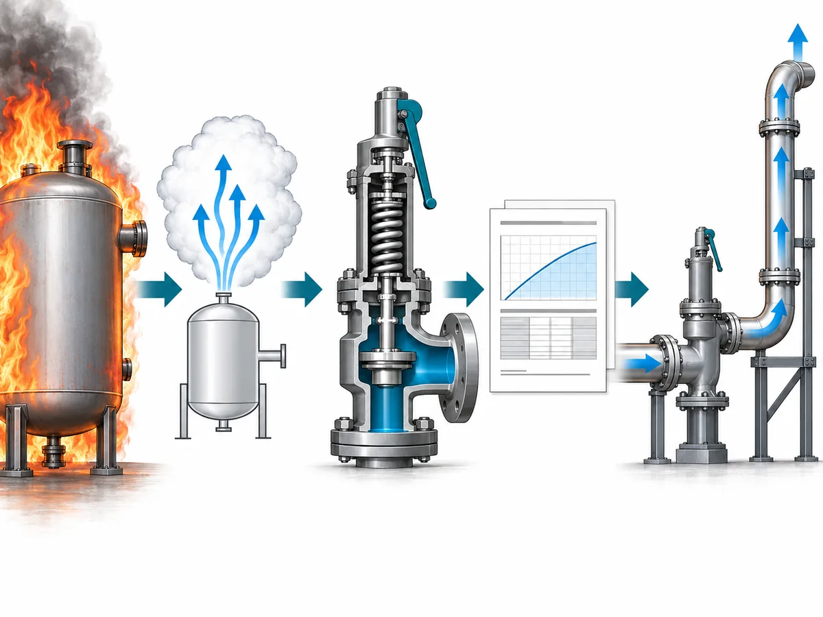
火灾工况泄放基准如何影响 PSV 定径与系统校核
一旦外部火灾分析得出所需泄放量,工艺侧工况计算的主要任务即已完成。它已确定了压力泄放系统必须处理的泄放需求。.
但这尚未证明某一具体阀门适用。.
下一阶段是设备定径与排量验证;更完整的方法属于 安全阀定径和认证泄放能力 指南。根据相关定径方法,利用所需泄放量、泄放压力、泄放温度、流体相态及其他适用物性来确定所需流通面积。随后可选定阀门或孔径,但其制造商文件记载的或经认证的排量必须在适用排量基准下满足所需负荷。.
这些量必须保持区分:
所需泄放量 ≠ 所需流通面积 ≠ 选定孔径 ≠ 公称连接尺寸 ≠ 文件记载或经认证的排量。.
一个阀门可与另一阀门具有相同的进口连接,但流通面积或排量仍可能不同。两个阀门可具有相同的整定压力,但排量或背压特性仍可能不同。不应将熟悉的孔径代号视为超出适用制造商或认证依据的排量证明。.
阀门也是管道系统的一部分
排量验证并不止于阀门接管处。.
较大的外部火灾负荷会对进口管线、出口管线和排放系统提出显著要求。进口压力损失会影响阀门性能。积聚背压或叠加背压会改变阀门处的有效工况。若一场火灾影响多台设备,共用泄放总管可能必须处理同时发生的负荷。出口管道、火炬或放空系统的阻力以及最终排放位置也必须与所选压力泄放装置相匹配。.
这并不意味着本文应成为完整的火炬管网或背压设计指南。重要的界限更简单:火灾工况负荷必须传递到系统验证中,而不能在得出一个阀门排量数值后就视为完成。.
火灾工况也不会自动选定常规弹簧式、平衡波纹管式或先导式结构。结构形式取决于实际背压、使用工况、压力和温度、稳定性要求、安装条件及制造商限制。仅凭“火灾工况”并不能作为阀门结构形式的决定依据。.
火灾工况用于设计前必须确认哪些内容
有效的外部火灾分析应留下可追溯的设计依据。在将分析结果用于选择或确定泄压装置之前,工程师应能够回答以下问题。.
- 具体保护的是什么设备? 确定容器及其相关设计压力或 MAWP 依据。.
- 为什么外部火灾是可信的? 明确火源、设备暴露情况和项目假设。.
- 存在多少物料存量? 确定与事件相关的液位、流体组成和相态行为。.
- 适用哪种火灾计算方法? 确认经验液体池火方法是否适用,或是否需要采用不同的分析处理方法。.
- 哪些压力和温度定义了泄放状态? 应将工作压力、整定压力、超压/压力积聚依据和泄放压力区分开来。.
- 热输入是如何确定的? 记录润湿/暴露面积基准以及任何环境、保温、排放或其他缓解假设。.
- 所需泄放量是如何计算的? 保留热力学基准,包括重要的相态或组分限制。.
- 该计算依据哪个标准及版本? 确认实际项目要求,而不是假定所有引用的标准同时适用。.
- 所选设备能否证明具有足够的排量? 采用所选阀门及孔径适用的制造商和认证/文件依据。.
- 连接的泄放系统能否处理该流量? 视情况检查入口损失、背压、出口管道和排放系统。.
如果其中任何一项未知,该不确定性应在工程审查中保持可见。缺失的输入不应以公称阀门尺寸、样本最大值或熟悉的经验法则替代。.
工程下一步
针对外部火灾工况的工程评审,请准备受保护设备数据、可信的火灾场景、工艺介质及相态、容器存量或液位、工作压力与设计压力/MAWP 信息、整定压力基准、泄放条件、火灾暴露假设、所需泄放负荷或已有计算依据,以及相关的下游背压或排放系统信息。.
这些信息可使沟通从真实的超压保护问题入手,而不是从猜测的阀门尺寸开始。.
申请工程审查
为评审外部火灾泄放工况,请提供受保护容器及可信的火灾场景、工艺介质及相态、容器存量或液位、工作压力与设计压力/MAWP 信息、整定压力基准、泄放条件、火灾暴露假设、所需泄放负荷或已有计算依据,以及相关的背压或排放系统信息。阀门排量、配置及最终适用性应结合所选产品数据、适用标准和项目要求予以确认。.
申请工程审查