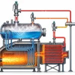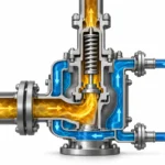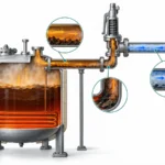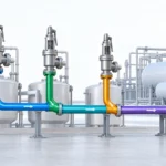
Compare thermal relief and pressure safety valve duties in LNG/LPG piping, including trapped liquid, capacity, phase, back pressure and RFQ checks.

Nelle tubazioni LNG e LPG, una valvola di sicurezza termica e una valvola di sicurezza per pressione non sono due principi di protezione opposti.
Una valvola di sfioro per dilatazione termica è essa stessa un dispositivo di protezione contro le sovrappressioni. La differenza utile è la seguente condizione di sfioro: qual è la causa dell'aumento di pressione, quale sezione è protetta, quale stato del fluido raggiunge il dispositivo e quale carico deve scaricare il dispositivo.
CGA PS-28
descrive una valvola di sfioro per dilatazione termica come un dispositivo di protezione contro le sovrappressioni utilizzato su sistemi di tubazioni per prevenire sovrappressioni causate dalla dilatazione termica di un volume limitato di fluido di processo intrappolato, inclusi i casi che coinvolgono liquidi criogenici o gas freddi intrappolati tra valvole o altri dispositivi.
Questa definizione è ristretta e utile: identifica uno specifico meccanismo di sovrappressione anziché una classe universale di valvole.
Una sequenza ingegneristica affidabile è quindi: definire la sezione protetta → identificare il meccanismo credibile di aumento della pressione → stabilire la capacità di scarico richiesta → verificare la valvola e il percorso di scarico installato.
Pressione di taratura, sovrappressione, accumulo, blowdown, capacità di scarico e contropressione sono termini correlati, ma non intercambiabili. Le loro relazioni ammissibili dipendono dal codice di riferimento, dall'apparecchiatura protetta e dalla configurazione della valvola, pertanto questo articolo non applica una percentuale o una soglia universale.
Un liquido bloccato che si riscalda all'interno di una sezione di tubazione isolata può creare un carico di dilatazione termica. Un altro sistema può invece presentare un caso credibile di sovrappressione dovuto a flusso bloccato, pompa, generazione di vapore, incendio o altro. Tali casi non devono essere ridotti a una singola scelta di prodotto “TRV versus PSV”.
API 521
riguarda i sistemi di scarico e depressurizzazione per impianti, inclusi i terminali LNG, mentre il quadro dei sistemi di scarico di API separa l'identificazione delle cause, la portata di scarico richiesta e la verifica del sistema di smaltimento a valle.
Il nome della valvola è quindi un punto di partenza, non la specifica tecnica.
Sfioro termico e sicurezza di pressione: qual è la vera differenza?
La vera differenza è prima la funzione, poi l'hardware.
Una funzione di sfioro per dilatazione termica esiste perché un fluido intrappolato cambia condizione e genera pressione mentre si riscalda. Il dispositivo di protezione risponde comunque alla pressione.
“Termico” descrive la causa della sovrapressione; non trasforma il dispositivo in una valvola azionata dalla temperatura. CGA PS-28 chiarisce particolarmente bene questa distinzione classificando la valvola di sfioro per dilatazione termica come dispositivo di protezione contro la sovrapressione.
“Anche ”PSV“, ”PRV“, ”valvola di sicurezza“ e ”valvola di sfioro" non devono essere considerati termini universalmente intercambiabili tra loro.
ISO 4126-1, per esempio, specifica i requisiti generali di prodotto per le valvole di sicurezza e dichiara esplicitamente di essere una norma di prodotto e non una norma di applicazione.
ASME BPVC Sezione XIII
fornisce separatamente le regole di protezione contro la sovrapressione che coprono i dispositivi di sfioro, la certificazione della capacità, l'installazione e i requisiti correlati. La norma di progetto applicabile, la scheda tecnica e la documentazione della valvola contano quindi più della sola abbreviazione.
Nella pratica di verifica, mantenere separati quattro termini di pressione. Pressione di taratura è la taratura della valvola utilizzata come riferimento di apertura in condizioni di prova o di servizio specificate. Sovrapressione è l'aumento di pressione al di sopra della pressione di taratura durante lo sfioro. Accumulo riguarda l'aumento di pressione del sistema protetto al di sopra della sua base ammissibile di riferimento durante un evento di sovrapressione. Scarto in chiusura è la differenza di pressione tra il comportamento di apertura e di richiusura. La documentazione API 520 e ASME sulla protezione contro la sovrapressione considera questi come parametri di progetto o prestazione distinti; i limiti esatti dipendono dal codice e dall'applicazione.
| Punto di confronto | Servizio di sfioro per dilatazione termica | Altro servizio di sfioro |
|---|---|---|
| Domanda principale | Un volume di fluido intrappolato può aumentare di pressione al variare delle sue condizioni? | Quale altro meccanismo credibile può causare sovrapressione nel sistema protetto? |
| Primo elemento da definire | Sezione protetta isolata e inventario intrappolato | Sistema protetto e scenario di sovrapressione |
| La denominazione della valvola definisce la capacità? | No | No |
| La dimensione della tubazione definisce la capacità richiesta? | No | No |
| Una corretta pressione di taratura garantisce una protezione adeguata? | No; il dispositivo deve anche avere una capacità di scarico adeguata ed essere collegato al volume protetto corretto. | No; capacità, stato di scarico e condizioni di installazione devono comunque essere verificati. |
| Che cosa determina in ultima analisi la selezione? | Il servizio richiesto più le effettive condizioni di servizio e di installazione | Il servizio richiesto più le effettive condizioni di servizio e di installazione |
Per un confronto più ampio della terminologia, consultare la
Guida PRV vs PSV vs valvola di sicurezza vs valvola di sfioro.
Questo articolo utilizza solo la terminologia necessaria per prendere la decisione sulle tubazioni LNG/LPG.
Quando una tubazione LNG o LPG diventa un caso di scarico termico?
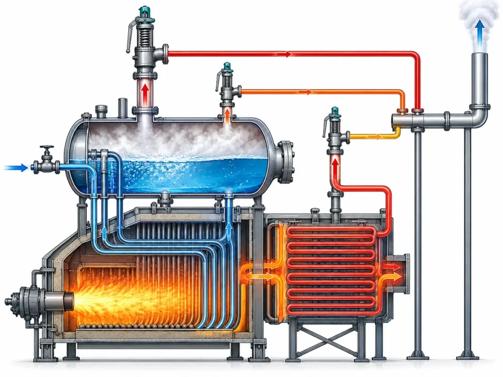
Partire dal confine di pressione, non dal catalogo delle valvole. Un caso di scarico termico diventa un candidato credibile quando un volume finito di fluido può essere isolato e il riscaldamento, la dilatazione termica o un applicabile cambiamento di stato criogenico possono aumentare la pressione mentre quella sezione rimane bloccata.
- Define the protected section. Identify the valves, equipment or other boundaries that isolate it.
- Confirm whether fluid can actually become trapped. An LNG or LPG line does not become a thermal-relief case simply because the medium is liquefied gas.
- Establish the trapped fluid and state. Liquid, cold gas and a potentially changing phase should not be assumed interchangeable.
- Identify the pressure-rise mechanism. Determine whether warming or thermal expansion is actually the credible cause.
- Only then establish the thermal-relief duty and required capacity.
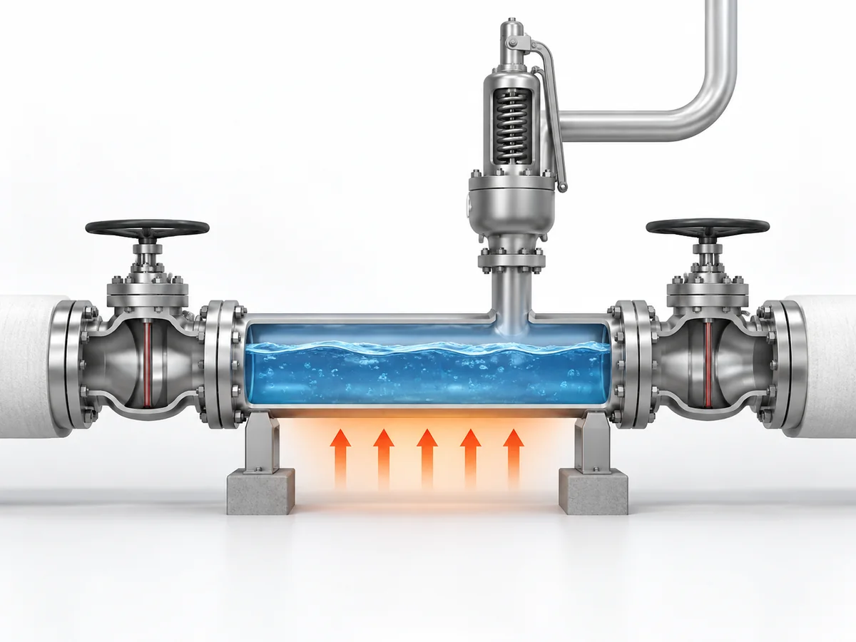
Within its specific scope for LNG road-vehicle fuelling stations,
ISO 16924:2026
defines a thermal relief valve around protection against excess pressure caused by cryogenic liquid vaporization or by warming of cold gas trapped in an isolated pipeline section or other small component.
That definition is useful for understanding the LNG thermal-relief mechanism, but the standard’s fuelling-station scope should not be expanded into a universal rule for every LNG terminal or process plant.
A typical isolated section between two shutoff boundaries is easy to visualize, but it is not the only possible configuration. What matters is whether the proposed relief device has an unobstructed pressure connection to the actual trapped volume throughout the operating and isolation states that create the case.
Scenario ingegneristico illustrativo: a transfer line is isolated at both ends after LNG or LPG movement stops. A small trapped liquid inventory remains in the line and subsequently warms from ambient heat leak. No pump has to be running for the pressure to rise. The engineering response is not to choose a “thermal valve” by connection size; it is to define the trapped volume, establish the thermal-relief load, verify the pressure basis, and confirm that the selected device protects that exact section.
Identifying a thermal-expansion case also does prescrive complete the valve selection. Set-pressure basis, required relieving capacity, phase, temperature, inlet and outlet conditions, back pressure and discharge destination remain separate verification items. The fact that thermal-relief loads are often smaller than major process-upset loads does not justify assuming that any small valve will be adequate.
When Is a Thermal-Relief Valve Not Enough?
A thermal-only assumption is no longer sufficient when another credible pressure-rise mechanism exists—or when the actual relieving condition has not yet been established.
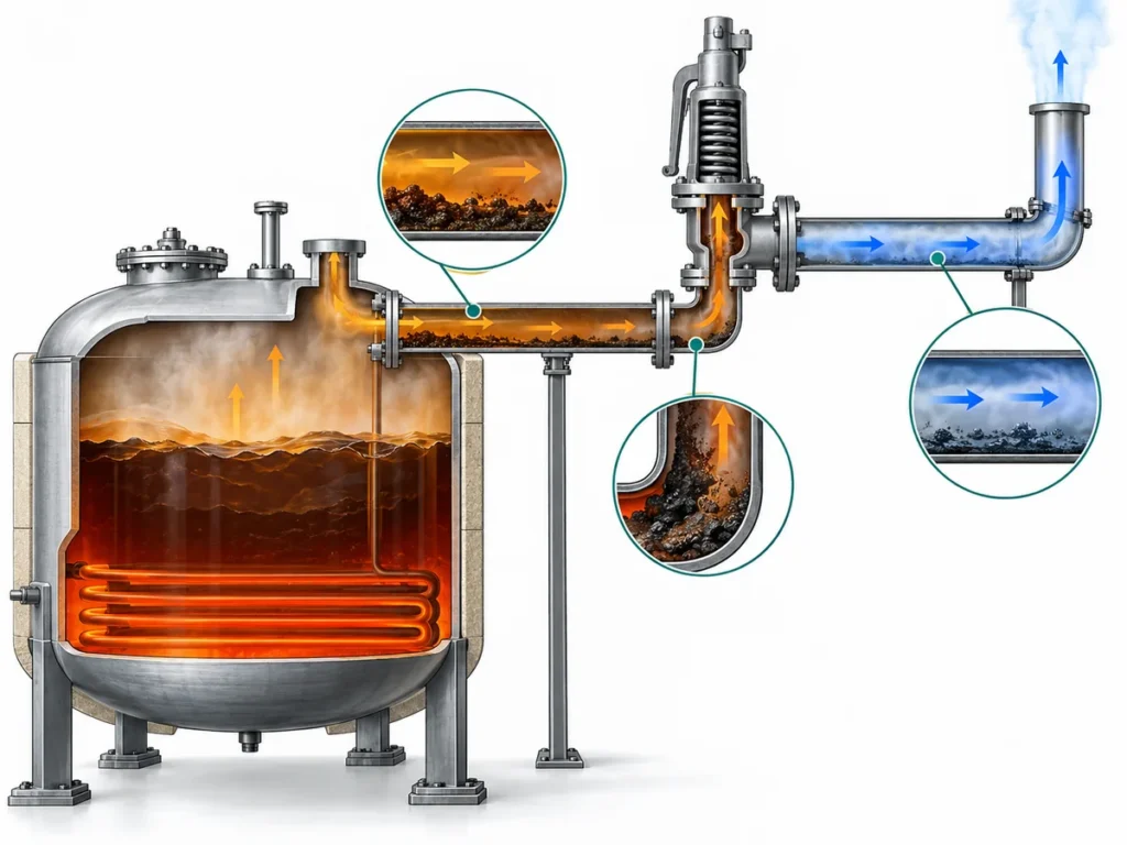
API 521 addresses pressure-relieving and depressuring systems rather than treating pressure relief as a catalogue-selection exercise. Depending on the protected system, further review may be required when there is another process pressure source, a blocked outlet or continuing inflow, a pump-related overpressure condition, vapor generation or another significant phase change, external heat exposure where applicable, an undefined protected boundary, an unknown required relieving rate, or an uncertain liquid, vapor or two-phase relieving state.
The point is not to build a long list of every possible relief scenario. It is to recognize when the thermal-expansion model no longer describes the complete problem.
Two-phase uncertainty is particularly important.
ISO 4126-10:2024
provides a dedicated sizing framework for gas/liquid two-phase flow in pressurized systems including piping. An unresolved LNG/LPG relieving condition therefore should not be silently forced into a single-phase assumption.
| If this is unresolved | Perché è importante |
|---|---|
| Protected section | You do not yet know what the valve actually protects. |
| Credible relief cause | The required duty cannot be defined reliably. |
| Capacità di scarico richiesta | Connection size cannot substitute for sizing. |
| Fase di scarico | Liquid, vapor and two-phase assumptions are not interchangeable. |
| Inlet piping condition | Pressure loss or restrictions between the protected system and the device can affect opening stability and available inlet pressure. |
| Downstream conditions | Outlet resistance and built-up back pressure can change installed valve behavior. |
API 520 Parte II
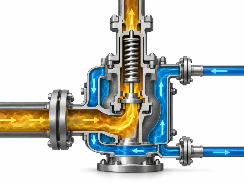
is specifically the installation part of the API 520 pressure-relieving-device standard. That is why inlet and outlet piping cannot be treated as accessories to the valve-selection calculation. The exact allowable inlet-loss and back-pressure limits depend on the governing standard, valve design and service; they should be checked against the project basis and manufacturer documentation rather than copied from a generic percentage.
Scenario ingegneristico illustrativo: a spring-loaded relief valve was originally reviewed against one discharge arrangement, but the plant later ties its outlet into a common header. The new header can increase built-up or variable back pressure during relieving. Even if the valve’s set pressure has not changed, its opening/reclosing behavior and effective capacity can require re-evaluation. The prevention step is to recheck the outlet hydraulic case whenever the disposal system changes, not just when the valve itself is replaced.
For the complete capacity calculation and certified-capacity workflow, use the
Guida al dimensionamento delle valvole di sicurezza e alla capacità di scarico certificata
rather than expanding this page into a sizing manual.
Can One Relief Device Cover Both Thermal Expansion and Other Overpressure Cases?
Possibly—but only after the relevant cases are checked independently.
Neither “the main PSV is larger, so it automatically covers thermal expansion” nor “thermal expansion always requires a physically separate valve” is a reliable selection rule.
API 520 Parte I
tratta il dimensionamento e la selezione dei dispositivi di sfioro, mentre
API 520 Parte II
addresses installation. The engineering review therefore needs to consider both the required duty and the installed system.
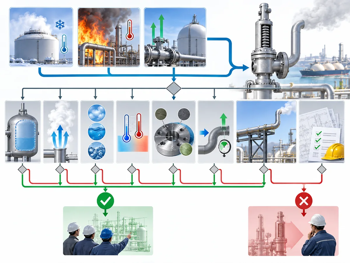
| Domanda di verifica | Why it can change the decision |
|---|---|
| Does the device protect the required boundary for each case? | A valve elsewhere in the system may not protect an isolated section. |
| Have the relevant relief causes been identified? | An omitted case cannot be covered by assumption. |
| Is the required relieving duty established for each applicable case? | Valve label and connection size do not establish load. |
| Does the candidate have appropriate capacity evidence? | Available capacity has to be compared with the required duty. |
| Is the relieving phase known? | A liquid case does not prove suitability for vapor or two-phase relief. |
| Is the set-pressure basis compatible with the protected system? | Opening pressure cannot be reviewed independently of the pressure boundary. |
| Are operating and relieving temperatures within documented limits? | Suitability at one temperature does not prove suitability at another. |
| Are body, trim, spring, guide, seat and seal arrangements supported for the service? | Component suitability is configuration-specific and can affect corrosion resistance, friction, leakage and stable motion. |
| Are back-pressure conditions supported? | Outlet pressure can affect opening, lift, capacity and reseating behavior depending on valve design. |
| Is the discharge path acceptable? | The valve is only one part of the complete relief path. |
| Are project documentation requirements satisfied? | Technical capability is not the same as project acceptance. |
What matters here is that capacity dominance is not the same as complete suitability. A candidate with enough capacity for a larger-flow scenario may still need separate verification for a lower-flow thermal case if that case involves a different protected section, phase, temperature, component limitation, back pressure or discharge route.
Capacity evidence also matters more than connection size. For code-covered pressure-relief devices, ASME Section XIII includes capacity and flow-resistance certification in its overpressure-protection scope, and the National Board’s
database di certificazione dei dispositivi di protezione contro la sovrapressione NB-18 del National Board
provides manufacturer/device certification information and certified relieving-capacity resources. A matching flange does not demonstrate that the candidate can pass the required relief load.
Scenario ingegneristico illustrativo: a valve can be adjusted to the intended set pressure yet still be an inadequate protective device if its verified relieving capacity is below the required case. The correction is not to “turn up” the set pressure or choose a larger connection by appearance; it is to compare the scenario’s required relieving rate with the candidate’s applicable certified or otherwise project-accepted capacity basis.
Spring-loaded and pilot-operated pressure-relief valves also should not be treated as interchangeable upgrades. Back pressure, operating margin, service cleanliness, sensing/pilot configuration, temperature and maintenance strategy can all influence architecture choice. Baker Hughes technical guidance on pilot-operated safety relief valves notes that severe dirty service can require filtration or isolation features and that clogging of interconnecting tubing can make a pilot-operated design a poor fit in some services.
Review the pilot-operated SRV technical note.
Likewise, nothing in this comparison means thermal expansion always requires a physically separate device. Whether one device can serve multiple duties is an engineering conclusion based on the complete system, not a rule that follows from the names “TRV” or “PSV.” This is a candidate-screening principle, not a statement that one valve has already received project, code or regulatory approval.
What Changes Between LNG and LPG Relief Service?
LNG and LPG can use the same decision framework, but they should not inherit the same service assumptions.
The shared questions are straightforward: What is protected? What causes the pressure rise? What fluid and phase reach the valve? What capacity is required? What temperature applies? What back pressure exists? Where does the relieved fluid go? What component and documentation evidence supports the candidate?
| Review variable | GNL | GPL |
|---|---|---|
| Temperatura | Cryogenic exposure can become a primary suitability boundary. | Use actual operating and relieving temperatures; do not inherit LNG assumptions. |
| Stato del fluido | Establish the actual LNG state at the protected section and during relief. | Establish actual LPG state rather than assuming liquid or vapor from the medium name. |
| Flashing / two-phase | Review when process conditions make it credible. | Review when process conditions make it credible. |
| Materiali | Verify the configured valve for the required low-temperature duty. | Verify compatibility and actual temperature requirements. |
| Sede / tenuta | Low-temperature performance may become a model-level constraint. | Fluid, temperature and leakage requirements still control. |
| Contropressione | Check the installed outlet system and valve architecture. | Check the installed outlet system and valve architecture. |
| Destinazione di scarico | Define it for the actual project. | Define it for the actual project. |
Cryogenic pressure-relief equipment deserves model-level verification rather than a generic statement such as “stainless steel is suitable for LNG.”
Baker Hughes technical guidance on cryogenic pressure-relief valves
identifies construction materials, trim design, anti-galling measures and sealing features as cryogenic design considerations. That evidence supports the need to verify the configured product; it does not establish that any specific ZOBAI model has the same construction or service capability.
Material review should therefore cover the full moving and sealing system, not only the pressure-retaining body: nozzle and disc surfaces, guides, spring environment, trim interfaces and seat/seal materials can all affect corrosion, galling, leakage or stable movement under the actual temperature and medium. For LNG service, differential contraction and low-temperature suitability must be confirmed from the product documentation rather than inferred from a generic alloy name.
Seat tightness is a separate purchase and test question from set pressure and certified capacity. API’s current catalog lists API Standard 527, Seat Tightness of Pressure Relief Valves; the standard covers test methods for metal- and soft-seated PRVs. If the project has a leakage requirement, state the required test basis and acceptance criteria in the purchase specification instead of assuming that “soft seat” or “metal seat” alone predicts field tightness.
Scenario ingegneristico illustrativo: a valve can fit the line mechanically and meet the intended set-pressure basis, yet still be a poor LNG candidate if its trim, guide or sealing materials are not supported for the actual low-temperature condition. The prevention step is to review the documented temperature/material configuration as a complete assembly, not to infer cryogenic suitability from body material alone.
For the broader application context, see
LNG and LPG pressure-relief applications.
For deeper component-level selection, see the
Guida alla selezione dei materiali per valvole di sicurezza.
For engineering review, the same questions can be used for LNG and LPG, but the answers should be verified separately for the actual service.
What Should You Confirm Before Selecting a Valve or Sending an RFQ?
Do not send only “Need a thermal relief valve, LNG, DNxx.” That does not define the protection duty.
A useful engineering enquiry should describe the system first and let the supplier verify the candidate second.
Define the protected system
- equipment or piping section being protected;
- isolation arrangement or system boundaries;
- credible overpressure scenario or scenarios;
- process reason pressure can rise.
If one relief device is expected to cover more than one case, identify every credited protected section and scenario instead of supplying only the “largest” case. A lower-flow thermal case can still have a different isolation boundary or different relieving state.
Provide the process and relief basis
- medium and relevant composition;
- normal fluid phase;
- expected relieving phase;
- pressione di esercizio;
- design or allowable pressure basis;
- required set-pressure basis;
- temperatura di esercizio;
- minimum relevant service temperature;
- expected relieving temperature;
- required relieving rate or the approved calculation basis.
If the phase is uncertain or two-phase relief is credible, state that uncertainty rather than assuming liquid-only or vapor-only sizing. If the governing code or owner specification limits set pressure, overpressure, accumulation or blowdown, provide that basis rather than asking the supplier to infer it from normal operating pressure.
Define the installed outlet conditions
- destinazione dello scarico;
- downstream system or header;
- expected superimposed and built-up back pressure where applicable;
- relevant outlet piping restrictions;
- flare, vent, process-return or other project-defined destination where applicable.
Back pressure is not merely a piping detail. Depending on valve architecture, it can affect opening pressure, lift, capacity and reseating behavior. Changes to a shared disposal header should trigger a valve/application review even when the protected equipment and set pressure are unchanged.
State the mechanical and material requirements
- requisiti di connessione in ingresso e in uscita;
- pressure class;
- spring-loaded, balanced or pilot-operated architecture if already fixed by the project;
- project material requirements for body, trim, nozzle, disc, spring/guide environment and seat/seal;
- medium compatibility requirements;
- leakage or seat-tightness test requirements;
- installation constraints, including orientation or accessibility where relevant.
Ask the supplier to confirm the candidate evidence
- modello e configurazione esatti;
- pressure and temperature limits;
- construction materials;
- seat and seal arrangement;
- applicable relieving-capacity evidence;
- supported fluid / phase basis;
- back-pressure limitations;
- connection details;
- set-pressure and blowdown adjustment/test basis where applicable;
- seat-tightness test basis where required;
- test, traceability and documentation package;
- conformity or certification only where it actually applies.
For inspection and repair planning, API RP 576 is the API recommended-practice framework for inspection of pressure-relieving devices in the oil and petrochemical industries. If the governing jurisdiction or owner specification requires National Board repair or test accreditation, verify the actual organization and scope in the
National Board Manufacturer and Repair Directory;
do not assume a VR or T/O requirement applies globally.
The buyer or process engineer defines the protected system and required duty; the supplier confirms what a specific valve configuration can support.
For the broader selection workflow, see the
Guida alla selezione delle valvole di sicurezza.
Classify the relief scenario before classifying the valve.
Once the protected boundary, relief cause, capacity, phase, temperature and installed conditions are defined, “thermal relief valve versus PSV” stops being a terminology debate and becomes a traceable engineering review.
Domande Frequenti
Is a thermal relief valve the same as a pressure safety valve?
A thermal-expansion relief valve is a pressure-relief device, but “thermal relief” describes a specific overpressure duty rather than proving a universally separate hardware class. The exact device terminology and configuration depend on the governing standard, service and project specification.
Can one pressure safety valve cover thermal expansion and another relief case?
It can be evaluated as a candidate for multiple cases, but capacity alone is not enough. The review must confirm that the device protects the required boundary and that set-pressure basis, required relieving rate, phase, temperature, materials, back pressure and discharge path are acceptable for each credited case.
How does back pressure affect a relief valve in LNG or LPG piping?
Back pressure can change opening, lift, capacity and reseating behavior depending on valve design. Built-up back pressure comes from outlet-system resistance during discharge; superimposed back pressure already exists at the valve outlet. The acceptable limits and the choice between conventional, balanced or pilot-operated designs must come from the governing standard and the specific valve documentation rather than a universal percentage.
Perché la capacità di scarico certificata è più importante delle dimensioni del raccordo?
Connection size tells you how the valve connects to the piping; it does not prove how much mass or volume the valve can discharge under the required relieving conditions. The required relief load must be compared with applicable capacity evidence for the actual fluid, pressure, temperature and valve configuration.
Qual è la differenza tra pressione di taratura, sovrapressione, accumulo e blowdown?
Set pressure is the valve’s opening reference under specified conditions. Overpressure is the rise above set pressure during relieving. Accumulation refers to the protected system’s pressure rise above its governing allowable basis during the event. Blowdown is the pressure reduction between opening and reseating behavior. Do not apply generic limits without the applicable code and project basis.
How often should an LNG or LPG pressure-relief valve be inspected or recertified?
There is no single interval that is correct for every service. Inspection and test frequency should follow the applicable jurisdiction, code, owner mechanical-integrity program, service severity and device history. API RP 576 and the relevant National Board/NBIC requirements can be part of that framework where they apply; project-specific requirements should control the published maintenance interval.