Safety Valve Engineering Comparison Field installation should preserve access, pipe support and a clear relief path for the selected dual PSV arrangement. Industrial engineering visual for article context; final layout should follow site and code requirements. Factory inspection helps confirm bolting, gauge connections, valve orientation and manifold assembly quality. Industrial engineering visual for article context; …

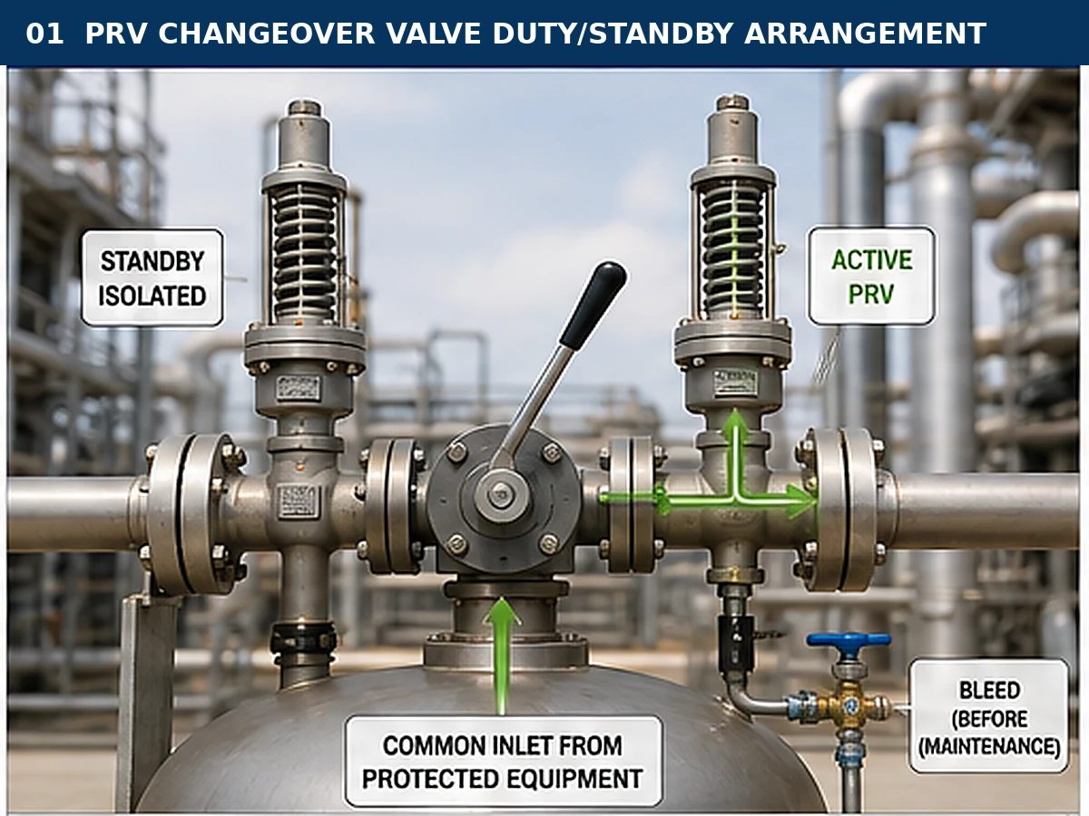
Safety Valve Engineering Comparison
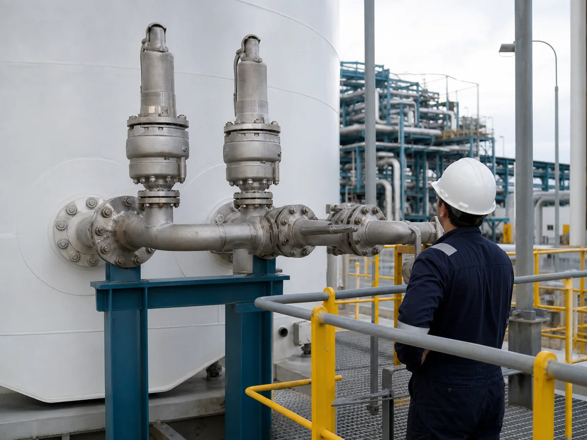
Industrial engineering visual for article context; final layout should follow site and code requirements.
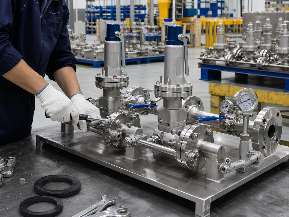
Industrial engineering visual for article context; it does not replace formal inspection procedures.
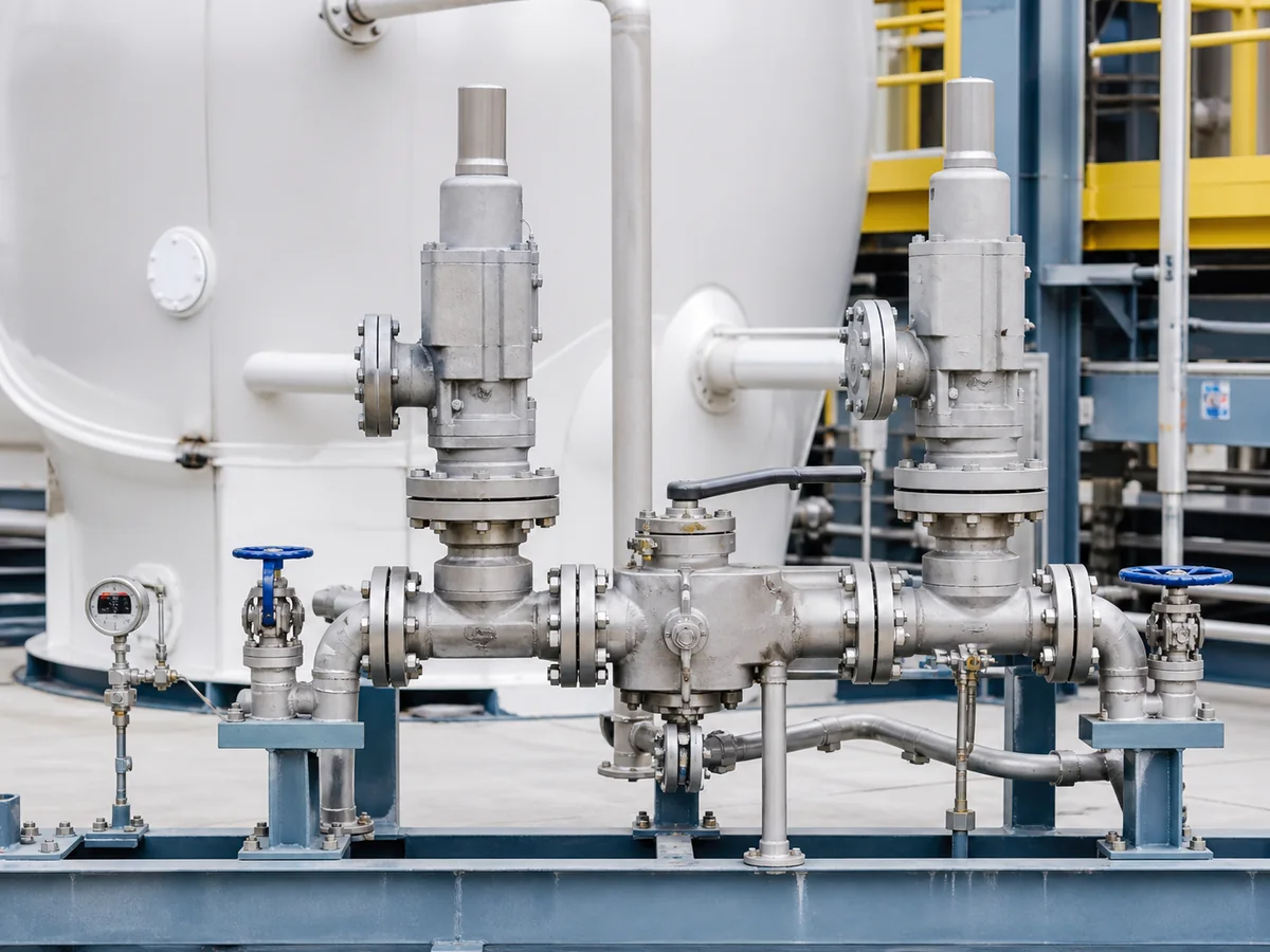
Industrial engineering visual for article context; final isolation and relief arrangements should follow project specifications.
Changeover Valve vs Separate Isolation Valves for Dual PSV Systems
Compare protection-path continuity, switching states, complete inlet loss, discharge coordination, maintenance isolation and RFQ evidence before selecting a dual-PSV arrangement.
Quick Answer
A dedicated changeover valve is often clearer when two pressure safety valves (PSVs) protect one system and one must remain available while the other is maintained. A purpose-designed selector can reduce independent switching actions. Separate isolation valves may still be evaluated where the applicable code, project specification and operating philosophy permit them, but the added valve-position combinations demand stronger locking or interlocking, indication, procedures and verification.
Neither arrangement is accepted by name, valve count, full-port designation or matching connections. At least one complete path must pass the required relieving flow in every permitted state. Review the equipment nozzle, inlet piping and fittings, selector or isolation device, documented PSV capacity, discharge piping, and superimposed and built-up back pressure. Before quotation, confirm the relief scenario, medium and phase, operating pressure, MAWP/design pressure, set pressure, required capacity basis, relieving temperature, piping layout, allowable states, materials, maintenance isolation and required documents.
Practical next step: send the process basis, piping layout, valve-state philosophy and required documents for a project-specific review before fixing the arrangement in an RFQ.
What Is Being Compared?
Both arrangements are intended to make one PSV available for inspection or maintenance while another PSV continues to protect the equipment. The difference is not the number of relief valves. It is how the process connection is directed, how many independent isolating elements can be operated, and how the permitted valve states are controlled.
A dedicated changeover arrangement uses a purpose-designed switching device, or a coordinated inlet-and-outlet switching system, to connect the protected equipment to the selected PSV. The device is not itself a PSV and does not provide overpressure protection. Its job is to establish the intended flow path.
A separate-isolation-valve arrangement places an individual isolation valve in each PSV branch. Depending on the discharge configuration, there may also be branch isolation valves downstream of the PSVs. This can be mechanically straightforward, but it creates several independent positions that must remain coordinated.
The terms duty and standby describe the intended service state. They do not prove that the duty branch is open, that the standby branch is depressurized, or that the selected PSV has sufficient capacity.
Preliminary Selection Matrix
This matrix is a screening tool, not an approval rule. A favorable row only identifies which arrangement may deserve further evaluation; the complete relief path, applicable rules and manufacturer data still govern the decision.
| Project condition | Dedicated changeover valve may be favored when | Separate isolation valves may be evaluated when | Evidence required before approval |
|---|---|---|---|
| Online PSV maintenance | One coordinated selector can preserve a defined active inlet path | The site can reliably control every inlet and outlet position | State diagram, maintenance boundary and approved operating procedure |
| Closed discharge header | A matched inlet/outlet switching design is available for the service | Independent outlet valves are positively coordinated with inlet selection | Discharge-state matrix, back-pressure analysis and manufacturer limits |
| Restricted plot space | A compact assembly improves layout without unacceptable resistance | The branch layout remains accessible, supported and drainable | Dimensioned arrangement, removal envelope, loads and pressure-loss calculation |
| Existing plant standardization | The specialized device can be supported with instructions and spares | Standard components fit an auditable position-control philosophy | Lifecycle support plan, lock/interlock specification and inspection records |
| Fouling, viscous or two-phase service | Internal geometry, drainage and resistance data are suitable and documented | Branch valves and piping can be assessed with service-specific methods | Fluid/phase data, relieving conditions, geometry and cleaning strategy |
| Hazardous or toxic medium | Isolation, bleed and containment features establish a verifiable maintenance boundary | Independent branches provide equivalent controlled isolation and safe disposal | Isolation plan, safe vent/drain destination, materials and leak-tightness requirements |
Decision rule: choose the arrangement only after confirming the active relief path, complete-path pressure loss, maintenance boundary and outlet-system behavior for every permitted state.
The First Requirement: Preserve an Adequate Relief Path
From a pressure-protection perspective, the first question is not “Which valve arrangement is cheaper?” It is:
In every permitted operating and transition state, is at least one adequately sized and correctly installed relief path connected to the protected equipment?
An open-looking handwheel, lever position or indicator is not enough. The path must be physically continuous and capable of delivering the required relieving flow. That requires confirmation of:
- the protected equipment and credible relief scenario;
- operating pressure, MAWP or design pressure, set pressure and the applicable accumulation or overpressure basis;
- medium, phase and relieving temperature;
- required relieving capacity and calculation basis;
- accepted PSV capacity data for the selected configuration;
- inlet pressure loss through the complete active path;
- discharge-system pressure and back-pressure effects;
- valve type, trim, seat, spring and bellows or pilot limits where applicable;
- the exact switching and isolation positions allowed by the design;
- the consequences of a wrong, intermediate or uncertain position.
Set pressure is not capacity. Connection size alone does not prove capacity. Two PSVs with the same inlet flange can have different effective orifices, coefficients, adjustments and accepted capacities. The complete assembly must be reviewed against the actual required duty.
How a Dedicated Changeover Valve Changes the Decision
A dedicated changeover valve can reduce operating ambiguity because one operating element selects between two branches. Designs differ, however, and the word changeover does not establish the internal flow geometry or the behavior at intermediate positions.
Potential advantages
- Fewer independent inlet-valve actions may be required during a controlled transfer.
- The duty and standby relationship can be easier to communicate on drawings and in operating procedures.
- A purpose-designed flow passage may offer a more predictable resistance basis when supported by manufacturer data.
- Mechanical stops, position indication or locking features may be integrated into the selector design.
- A matched inlet-and-outlet switching arrangement may help coordinate a closed-discharge system when the supplied design is intended for that purpose.
What can still go wrong
- An intermediate position may reduce the available flow area.
- The wrong internal porting assumption may be used in the piping review.
- The selected inlet and outlet paths may not correspond.
- The operator may rely on the handle position without confirming the actual branch condition.
- Trapped pressure may remain in the standby branch even after it appears isolated.
- The changeover device may add enough resistance to affect inlet pressure loss.
- A selector intended for one service, pressure class or flow direction may be incorrectly applied elsewhere.
Before RFQ, obtain the manufacturer’s flow-path drawing, allowable operating positions, pressure-temperature rating, material specification, seat or sealing details, resistance data, vent or bleed provisions, locking or interlocking features, and installation and maintenance instructions. A product label alone cannot establish suitability.
How Separate Isolation Valves Change the Decision
Separate isolation valves give designers more freedom in branch layout and component selection. That flexibility also increases the number of possible states. With two inlet valves, there are four basic open/closed combinations before any outlet valves, bypasses, vents or intermediate positions are considered.
Potential advantages
- Individual components may be familiar to the site maintenance team.
- Each branch can be isolated and serviced using conventional valve and piping practices.
- Layout can be adapted around existing piping when a code-compliant and project-approved arrangement is feasible.
- Replacement of one isolation valve may be more independent of the other branch.
What can still go wrong
- Both inlet valves may be closed through error or uncontrolled sequencing.
- The wrong branch may be isolated.
- An inlet valve may be open while its downstream discharge valve is closed.
- A valve may be left partially open, creating excessive resistance.
- A nominally full-port valve may still have an unsuitable bore, transition geometry or resistance at relieving flow.
- Locks, car seals, keys, interlocks or procedures may be defeated, omitted or inconsistently managed.
- The isolated branch may still contain hazardous pressure or fluid.
The term full-port is not an engineering acceptance result. It describes a feature of the valve, but it does not prove acceptable inlet pressure loss through the vessel nozzle, pipe, fittings and valve together. Manufacturer resistance data and the actual relieving-flow calculation remain necessary.
Side-by-Side Engineering Comparison
| Decision factor | Dedicated changeover valve | Separate isolation valves | What must be verified |
|---|---|---|---|
| Number of independent switching actions | Often lower, depending on design | Usually higher | Actual operating sequence and permitted states |
| Risk of both PSV inlets being isolated | Can be reduced by internal geometry, but must not be assumed | Requires strong controls against the both-closed state | Drawings, stops, locks, interlocks and procedures |
| Intermediate-position behavior | Design-specific | Each valve may be partially open or in an uncertain position | Minimum available flow area and transition rule |
| Inlet resistance | Added by the selector passage | Added by each branch isolation valve | Complete-path pressure-loss calculation at relieving conditions |
| Outlet coordination | May be integrated in a purpose-designed system | Requires separate coordination when outlet isolation is present | Inlet/outlet state matrix and discharge back pressure |
| Maintenance isolation | Standby branch may be selected out of service | Branch may be individually isolated | Bleed, vent, drain and verified zero-energy state |
| Position indication | May be integrated | Required for each relevant valve | Local visibility, remote indication if required, and fail-state response |
| Layout flexibility | Usually more standardized | Often more adaptable | Access, support, drainage, thermal expansion and maintenance envelope |
| Component replacement | May involve a specialized assembly | Can use separate valves subject to approved specification | Spares, materials, pressure class and manufacturer support |
| Human-factor exposure | Fewer actions can simplify control | More combinations require stronger administrative or mechanical safeguards | Site operating philosophy and independent review |
| Commercial review | Specialized device and documentation | Multiple valves, accessories and control measures | Total installed scope, not purchase price alone |
Decision summary: Choose the arrangement only after confirming the active relief path, complete-path pressure loss, maintenance boundary and outlet-system behavior.
Why Intermediate Valve Positions Matter
A switching system is not assessed only at its two final positions. The transition between positions may be the most important state.
For a dedicated changeover valve, confirm whether the internal design keeps one branch fully or adequately connected throughout movement, whether any overlap occurs, and whether the selector is permitted to stop between end positions. For separate isolation valves, confirm the required opening and closing sequence and how the system prevents a condition in which both branches are unavailable.
The following matrix is a functional review framework, not a universal operating procedure. The approved sequence must come from the actual valve design, project documentation and facility procedure.
| Functional state | PSV A inlet | PSV B inlet | Outlet path | Required verification |
|---|---|---|---|---|
| Normal duty A | Available | Standby condition | A discharge available | A path has required capacity; B state is controlled |
| Normal duty B | Standby condition | Available | B discharge available | B path has required capacity; A state is controlled |
| Controlled transition | Design-specific | Design-specific | Corresponding discharge path available | At least one adequate relief path remains available throughout movement |
| Maintenance on A | Isolated for work | Available | B discharge available; A condition controlled | A isolated, vented or drained as required, and pressure verified before work |
| Maintenance on B | Available | Isolated for work | A discharge available; B condition controlled | B isolated, vented or drained as required, and pressure verified before work |
| Abnormal or uncertain position | Unknown | Unknown | Unknown | Stop work or transition, verify positions and restore an approved protection state |
A selected valve position does not by itself prove adequate relieving flow, positive isolation or zero stored pressure.
Keep Pressure and Capacity Terms Separate
Dual-PSV reviews become unreliable when design, operating and certification terms are treated as interchangeable. Record the project definitions and applicable code basis explicitly.
| Term | Engineering meaning in this review | What it does not prove |
|---|---|---|
| Operating pressure | Normal or defined process pressure used to assess operating margin and stability | It is not the PSV set pressure or equipment MAWP |
| MAWP / design pressure | Equipment pressure boundary value as defined by the governing design documents | It is not automatically interchangeable with set pressure |
| Set pressure | Pressure at which the selected PSV is adjusted to begin its specified opening behavior | It does not state connection size, required load or relieving capacity |
| Overpressure / accumulation | Pressure increase above the relevant reference during relief, used according to the applicable rules | It is not a generic margin that can be selected without the scenario and code basis |
| Required relieving capacity | Calculated process load for the controlling approved relief scenario | It is not established by the number of installed PSVs |
| Certified or documented capacity | Accepted manufacturer capacity evidence for the exact valve configuration and stated conditions | It cannot be transferred from a similar-looking valve or connection size |
| Inlet pressure loss | Loss through the complete active inlet path at relieving conditions | It is not proven acceptable by a full-port label |
| Back pressure | Superimposed pressure before opening plus built-up effects during discharge, as applicable | It is not eliminated merely by naming a valve balanced or pilot-operated |
Flow Capacity and Inlet Pressure Loss Cannot Be Assumed from Nominal Size
The active PSV receives pressure through a complete inlet system. Every component between the protected volume and the PSV inlet can contribute resistance:
- equipment nozzle;
- branch connection or header;
- straight pipe;
- elbows, tees and reducers;
- changeover or isolation valve;
- inlet flange or threaded connection;
- any transition immediately at the PSV inlet.
The calculation should use the required relieving flow, actual fluid properties, phase, relieving pressure and relieving temperature. For two-phase, flashing, viscous, fouling, polymerizing or solidifying service, a simple single-phase shortcut may be inappropriate. The actual geometry and manufacturer resistance data matter.
A separate branch can appear generous on a layout while still having excessive resistance. Conversely, a compact changeover assembly cannot be accepted simply because the selector bore resembles the PSV inlet size. Review the worst credible active path, including any asymmetry between PSV A and PSV B.
If each PSV is intended to handle the full required load, verify each complete path independently. If capacity is shared between devices, the design basis, set pressures, accumulation limits and accepted capacity allocation require explicit engineering and code review. Do not assume that two installed PSVs automatically provide 200% capacity or redundancy.
Outlet Isolation, Back Pressure and Discharge-System Coordination
The inlet arrangement cannot be reviewed in isolation from the discharge system. A PSV with an open inlet and a closed outlet does not provide an acceptable relief path.
Where both PSVs discharge into a common closed header, confirm:
- the superimposed back pressure before the PSV opens;
- the built-up back pressure created during relief;
- the effect of other devices discharging into the same header;
- branch and header pressure loss;
- liquid collection, drainage and low points;
- thermal expansion and trapped-liquid risks;
- outlet isolation positions and their coordination with the inlet selection;
- reaction forces, supports and nozzle loads;
- the valve manufacturer’s back-pressure limits for the exact configuration.
Naming a valve balanced bellows or pilot-operated does not resolve the back-pressure review. Bellows designs have limits related to back pressure, bellows integrity, bonnet venting and service conditions. Pilot-operated systems depend on the pilot, sensing path, seals and service cleanliness, among other design-specific factors. Use manufacturer data for the selected model and configuration.
For atmospheric discharge, evaluate personnel exposure, noise, hazardous or flammable release, rain ingress, drainage, discharge direction and local environmental or regulatory requirements. A dual-PSV arrangement does not make an unsafe discharge location acceptable.
Maintenance Isolation Is Not the Same as Depressurization
Closing or switching a valve can isolate a branch from one pressure source, but it does not prove that the branch is safe to open. Pressure may remain trapped between the isolation device and the PSV, inside a closed outlet branch, or within liquid-filled cavities exposed to heating.
Before maintenance, the approved isolation plan should address:
- identification of the exact PSV and branch;
- confirmation that the alternate PSV path is available and adequate;
- inlet and outlet isolation positions;
- venting, bleeding or draining to a safe location;
- verification of zero pressure using an appropriate method;
- hazardous-energy control and lockout/tagout where applicable;
- residual fluid, toxicity, flammability, temperature and contamination;
- access, lifting, supports and flange-break precautions;
- required inspection, test and documentation before return to service;
- controlled restoration of the branch and final valve-position verification.
The terms isolated, vented, drained and zero energy should not be used interchangeably. Each condition needs its own confirmation.
Position Control: Mechanical Safeguards and Procedures
The required control level depends on the risk, applicable rules and facility philosophy. Possible measures include mechanical stops, trapped-key interlocks, locks, car seals, position indicators, limit switches, permissives, administrative procedures and independent verification.
No single feature is universally sufficient. A tag can be wrong. A lock can be placed on the wrong valve. A switch can indicate stem travel without proving a clear flow path. An interlock can be bypassed or mis-specified. The protection concept should therefore combine clear mechanical design, unambiguous drawings, controlled procedures, training, inspection and verification.
The cause-and-effect or valve-state documentation should cover abnormal conditions such as lost indication, a jammed selector, a leaking isolation valve, a partially open valve and mismatch between inlet and outlet positions.
Installation and Layout Checks
The selected arrangement must be physically maintainable as well as hydraulically acceptable. Review:
- upright PSV installation where required by the selected design;
- shortest practical inlet path consistent with layout constraints;
- correct flow direction through selector and isolation valves;
- access to handles, keys, locks, vents and drains;
- clear visual confirmation of valve position;
- piping support independent of the PSV body where required;
- nozzle loads, thermal growth and vibration;
- drainage of inlet and discharge piping;
- removal space for each PSV and the switching device;
- safe discharge routing from vents, drains and bonnet vents;
- avoidance of pockets that can collect liquid or solids;
- protection against environmental exposure, corrosion and accidental operation.
Material grade alone does not prove service suitability. Body, trim, seats, packing, gaskets, bolting, springs, bellows and pilot-system materials may face different process or environmental conditions. Confirm corrosion, temperature, pressure cycling, fouling and compatibility across the full assembly.
Medium, Material and Sealing Screen
The switching device, isolation valves and PSVs form one service assembly but may not share the same wetted materials or sealing limits. Use this screen to identify questions for the detailed materials and valve review.
| Service factor | Potential concern | What to confirm |
|---|---|---|
| Gas or clean vapor | Seat leakage, stability and discharge reaction | Seat design, blowdown behavior where relevant, piping support and accepted capacity basis |
| Liquid service | Drainage, hydraulic reaction, trapped liquid and thermal expansion | Low-point drains, body-cavity relief where required, outlet routing and liquid-service data |
| Two-phase or flashing flow | Sizing method and pressure-loss behavior may differ from simple single-phase assumptions | Approved calculation method, actual phase behavior and manufacturer application limits |
| Viscous, fouling or solidifying medium | Restricted passages, deposits, plugging and uncertain resistance | Minimum passages, heat tracing or cleaning needs, drainage and inspection frequency |
| Corrosive medium | Different exposure of body, trim, spring, bellows, pilot and seals | Full material list, corrosion allowance where applicable, compatibility evidence and environmental exposure |
| Toxic or flammable medium | Leakage, venting and maintenance release consequences | Seat/leakage requirements, contained vent/drain destination, packing or sealing arrangement and isolation verification |
| High or low temperature | Material toughness/strength, seal limits and thermal movement | Pressure-temperature ratings for every component, gaskets, packing, bolting and support flexibility |
This screen does not select a material grade. Final materials, seat, spring, bellows, packing and gasket choices require the actual composition, temperature, pressure, corrosion mechanisms and manufacturer limits.
When a Dedicated Changeover Valve Is Often Considered
A dedicated changeover arrangement is commonly considered when:
- continuous pressure protection is required while one PSV is removed for inspection or maintenance;
- the site wants a clearly defined duty/standby selection with fewer independent inlet actions;
- a compact, purpose-designed assembly can fit the layout;
- manufacturer flow-resistance and switching-state data are available;
- matched inlet and outlet selection is required for a closed discharge system;
- the project can support the specialized device, spare parts and maintenance instructions.
It may be less attractive when the available device cannot meet the pressure-temperature, material, resistance, drainage, access or project-standard requirements, or when the specialized assembly creates an unacceptable maintenance or spare-parts dependency.
When Separate Isolation Valves May Be Evaluated
Separate isolation valves may be evaluated when:
- the applicable code, jurisdiction and project specification permit the arrangement;
- the site has a robust and auditable valve-position control philosophy;
- the complete piping layout maintains acceptable inlet and outlet conditions;
- every permitted state and transition has been reviewed;
- the valves provide suitable pressure-temperature ratings, materials, bore geometry and resistance data;
- the isolation, venting, draining and return-to-service method is defined;
- inspection and operations teams accept the added number of independent positions.
They should not be selected merely because standard valves are readily available or appear less expensive. The total scope may include additional valves, locks or interlocks, indicators, bleed arrangements, supports, procedures, training, inspection and documentation.
Common Procurement and Design Mistakes
- Buying by connection size and set pressure only. These fields do not establish required or accepted capacity.
- Assuming two PSVs equal automatic redundancy. One branch may be blocked, undersized or exposed to an unavailable discharge path.
- Treating full-port as proof of acceptable inlet loss. The complete active path must be calculated.
- Ignoring transition states. End positions alone do not describe switching safety.
- Coordinating inlet valves but not outlet valves. This can create an open inlet with a blocked discharge.
- Calling a branch isolated without venting and pressure verification. Trapped pressure and hazardous fluid can remain.
- Using a generic back-pressure assumption. Actual superimposed and built-up back pressure must be evaluated.
- Replacing by appearance or nameplate connection size. Orifice, capacity basis, materials and certified configuration may differ.
- Specifying only a standard name. The applicable edition, service, project specification, documentation and jurisdiction still require confirmation.
- Comparing purchase price instead of installed protection scope. Engineering, piping, controls, spares and lifecycle maintenance can change the result.
Actionable Tables / Checklists
Verification and Document Matrix
| Review item | Typical evidence | Responsible review role | Release condition |
|---|---|---|---|
| Relief basis and required load | Approved scenario calculation and process data | Process engineering | Controlling case and capacity basis are identified |
| PSV selection | Manufacturer datasheet, capacity evidence and configuration details | Pressure-relief / mechanical engineering | Selected device covers its assigned duty under accepted rules |
| Inlet and outlet hydraulics | Isometrics, line list, resistance data and calculation | Process and piping engineering | Both selectable paths and the discharge system are acceptable |
| Permitted valve states | P&ID, state matrix, cause-and-effect and operating procedure | Operations, process safety and engineering | No permitted state removes the required protection path |
| Maintenance isolation | Isolation plan, vent/drain detail and energy-control procedure | Maintenance and operations | Alternate protection and zero-pressure verification are defined |
| Materials and ratings | Material list, pressure-temperature ratings and compatibility review | Materials / mechanical engineering | All pressure-containing and sealing components suit the service |
| Inspection and return to service | Inspection/test records, set-pressure documentation where applicable, valve-position sign-off | Inspection, quality and operations | Required records are accepted and the active path is independently confirmed |
Role names indicate functions only. The owner, EPC, manufacturer and jurisdiction determine the actual approval authorities and document sequence.
Engineering Inputs Required Before Arrangement Approval
| Data group | Minimum information | Why it changes the decision |
|---|---|---|
| Protected equipment | Equipment type, protected volume, nozzle and MAWP/design pressure | Defines the pressure boundary and connection path |
| Relief basis | Credible scenario, blocked outlet/fire/utility failure or other approved case, allowable accumulation basis | Establishes why relief is required and the controlling load |
| Process conditions | Medium, composition, phase, operating pressure and temperature | Changes sizing, materials, fouling and discharge behavior |
| Relieving conditions | Relieving pressure, temperature, required mass or volumetric capacity and calculation method | Defines the hydraulic duty |
| PSV data | Set pressure, blowdown if relevant, orifice, accepted capacity data, valve type and configuration | Confirms whether each active device can handle the assigned load |
| Inlet path | Nozzle, pipe sizes/lengths, fittings, reducers, selector or isolation valve data | Supports complete-path pressure-loss review |
| Outlet path | Branch piping, common header, discharge destination and other simultaneous loads | Supports back-pressure and disposal-system review |
| Switching philosophy | Permitted positions, transition sequence, locking/interlocking and indication | Prevents loss of protection through an incorrect state |
| Maintenance philosophy | Isolation, bleed/vent/drain, pressure verification and return to service | Defines whether safe online maintenance is achievable |
| Materials | Body, trim, seat, packing, gaskets, spring, bellows or pilot materials | Screens compatibility and temperature/corrosion risks |
| Codes and documents | Applicable code edition, jurisdiction, project specification, drawings, calculations and test records | Defines approval and evidence requirements |
Arrangement Review Checklist
Final Decision Checklist
Choose a dedicated changeover valve only after confirming:
- its internal flow paths and transition behavior;
- resistance data for the actual size and configuration;
- pressure-temperature and material suitability;
- inlet/outlet coordination where both sides are switched;
- isolation, bleed and maintenance provisions;
- spare parts, instructions and lifecycle support.
Choose separate isolation valves only after confirming:
- the both-closed condition is prevented or controlled as required;
- partial-open and wrong-branch risks are addressed;
- full-port designation is supported by complete-path pressure-loss verification;
- inlet and outlet positions cannot create a blocked relief path;
- the site can sustain the required lock, interlock, indication, procedure and audit controls;
- online maintenance isolation and pressure verification are practical.
Composite Engineering Scenarios
Composite Engineering Scenario for Training 1: One Selector, Two Independent Discharge Branches
A process vessel requires one PSV to remain available while the second PSV is removed for periodic inspection. A compact inlet changeover device is proposed, but each PSV has its own discharge branch to a common header.
The engineering review does not stop at selecting the inlet. The team maps each selector position to the corresponding available discharge branch, calculates inlet loss for both sides, and checks back pressure for the common-header cases. The maintenance plan also requires a safe method to confirm that the standby branch is depressurized.
Lesson: A dedicated inlet selector can simplify the duty change, but it does not automatically coordinate the outlet system or establish a safe maintenance boundary.
Composite Engineering Scenario for Training 2: Separate Full-Port Isolation Valves
An existing installation has two PSV branches with individual full-port isolation valves. The proposal is to keep the arrangement because the valve bore matches the nominal inlet pipe size.
The review finds that one branch includes additional fittings and a longer run. Both paths therefore require separate pressure-loss calculations using the required relieving flow and actual fluid properties. Operations also needs a controlled sequence and position-verification method that prevents both inlet valves from being closed.
Lesson: Full-port construction and equal nominal sizes do not prove equal hydraulic performance or an acceptable operating philosophy.
Composite Engineering Scenario for Training 3: Closed Header with Outlet Isolation
Two PSVs discharge to a closed relief header. Inlet isolation is well controlled, but separate outlet valves can be operated independently.
The state review identifies a possible mismatch: the selected duty PSV could have an open inlet and closed outlet. The design team therefore evaluates a coordinated mechanical or procedural control, verifies header back pressure and confirms the correct venting and pressure-verification method before maintenance.
Lesson: The available protection path runs from protected equipment to the final discharge system. Inlet selection alone is incomplete.
Technical References
Use the editions adopted by the project, owner and jurisdiction. These official pages identify the documents and their scope; they do not replace access to the applicable standard.
- API 520 Part I — sizing and selection of pressure-relieving devices within its stated scope.
- API 520 Part II — installation and engineering analysis within its stated scope.
- API 521 — pressure-relieving and depressuring systems within its stated scope.
- ASME BPVC Section VIII, Division 1 — pressure-vessel construction rules and related relief requirements where adopted.
- ISO 4126-1 and ISO 4126-9 — safety-valve product and application guidance within their respective scopes.
- OSHA 29 CFR 1910.147 — hazardous-energy control where this United States rule applies.
Frequently Asked Questions
Is a changeover valve always required for two PSVs?
No. The required arrangement depends on the applicable code, jurisdiction, project specification, relief duty, piping design and operating philosophy. A dedicated changeover device can reduce switching ambiguity, while a separate-isolation arrangement may be evaluated where it is permitted and adequately controlled. Neither option is automatically acceptable.
Can both PSVs be isolated at the same time?
Not as a normal state when they are the required protection for operating equipment. Every permitted state must preserve the required overpressure protection unless the protected equipment has been safely removed from service and isolated under an approved procedure. The exact requirements must be confirmed for the project and jurisdiction.
Does a full-port isolation valve eliminate inlet pressure-loss concerns?
No. Full-port describes the valve bore configuration; it does not account for the vessel nozzle, pipe length, fittings, reducers, internal geometry or relieving-flow conditions. Calculate pressure loss through the complete active path using actual geometry and suitable manufacturer data.
Must each PSV handle the full required relieving capacity?
That depends on the approved protection philosophy. In many duty/standby arrangements, each PSV is expected to protect the full assigned case, but a multiple-device design may allocate capacity differently. Required capacity, set pressures, accumulation basis and accepted capacity data must be reviewed under the applicable rules. Do not infer capacity from the number of valves.
Does the standby PSV have zero pressure after switching?
Not necessarily. Pressure or hazardous fluid may remain trapped in the inlet branch, body cavities or discharge piping. Isolation must be followed by the required venting, draining and pressure verification before maintenance.
How should inlet and outlet valves be coordinated?
The permitted state matrix should ensure that the selected PSV has both an available inlet and an available discharge path. The means may be a purpose-designed coordinated changeover assembly, mechanical interlocking, trapped-key control, monitored positions or an approved procedure. The appropriate method is project-specific.
Can a balanced bellows or pilot-operated PSV solve all back-pressure problems?
No. Each design has operating limits and application requirements. Back pressure, fluid cleanliness, materials, sensing arrangement, bellows or pilot details and manufacturer limits must be checked for the exact selected model and service.
What should an RFQ include for a dual-PSV arrangement?
Include the protected equipment, relief scenario, medium and phase, operating pressure, MAWP/design pressure, set pressure, required capacity and basis, relieving temperature, inlet and outlet layout, back pressure, valve-state philosophy, materials, applicable code and specification, required documentation, quantity and available drawings or datasheets.
Engineering Review
Review the Complete Dual-PSV Protection Path Before Quotation
For an engineering review, provide:
- protected equipment and relief scenario;
- medium, composition and phase;
- operating pressure and temperature;
- MAWP or design pressure;
- set pressure;
- required relieving capacity and calculation basis;
- relieving temperature;
- expected superimposed and built-up back pressure;
- inlet and outlet connection details and piping layout;
- proposed changeover or isolation-valve arrangement;
- PSV type, materials, seat, spring, bellows or pilot details where known;
- applicable code edition, project specification and local requirements;
- quantity, drawings, existing datasheet, nameplate information and required documents.
ZOBAI can review the supplied duty and arrangement data against available product configurations. Final design approval remains subject to verified process data, manufacturer documentation, the applicable code and project engineering authority.
Technical Review Scope
Technical Content Scope
This article is intended to support engineering comparison and RFQ preparation for dual-PSV switching arrangements. It does not replace a relief-load calculation, piping stress review, hazardous-energy procedure, manufacturer instruction or approval by the responsible engineer, owner, inspector or authority having jurisdiction.
Standards and Liability Note
This article provides engineering interpretation, not the text of any standard. Requirements vary with the protected equipment, service, jurisdiction, project specification and edition adopted by the owner or authority. Confirm the applicable editions of API 520, API 521, ASME BPVC, ISO 4126 or other governing documents before design approval.
Final selection and installation require verified relief scenarios, process conditions, required capacity, accepted manufacturer capacity data, complete inlet and outlet calculations, materials review, approved drawings, operating and maintenance procedures, and local regulatory review. No statement in this article certifies a specific product, installation or facility as code-compliant.