Safety Valve Working Principle What Is a Changeover Safety Valve? A changeover safety valve arrangement uses two PRVs and a selector so one valve protects the equipment while the other can be isolated for inspection or maintenance. Duty / standby principle Continuous qualified relief path Switching and maintenance boundary Not automatically double capacity On this …

Safety Valve Working Principle
What Is a Changeover Safety Valve?
A changeover safety valve arrangement uses two PRVs and a selector so one valve protects the equipment while the other can be isolated for inspection or maintenance.
- Duty / standby principle
- Continuous qualified relief path
- Switching and maintenance boundary
- Not automatically double capacity
Quick Answer
A changeover safety valve is normally a complete duty/standby arrangement, not one special relief valve. A selector connects the protected equipment to one PRV while the second PRV remains available as the standby unit.
Before maintenance, confirm the new active path, then isolate, vent or drain, and verify the standby branch pressure-free. Two installed PRVs do not automatically provide double relieving capacity.
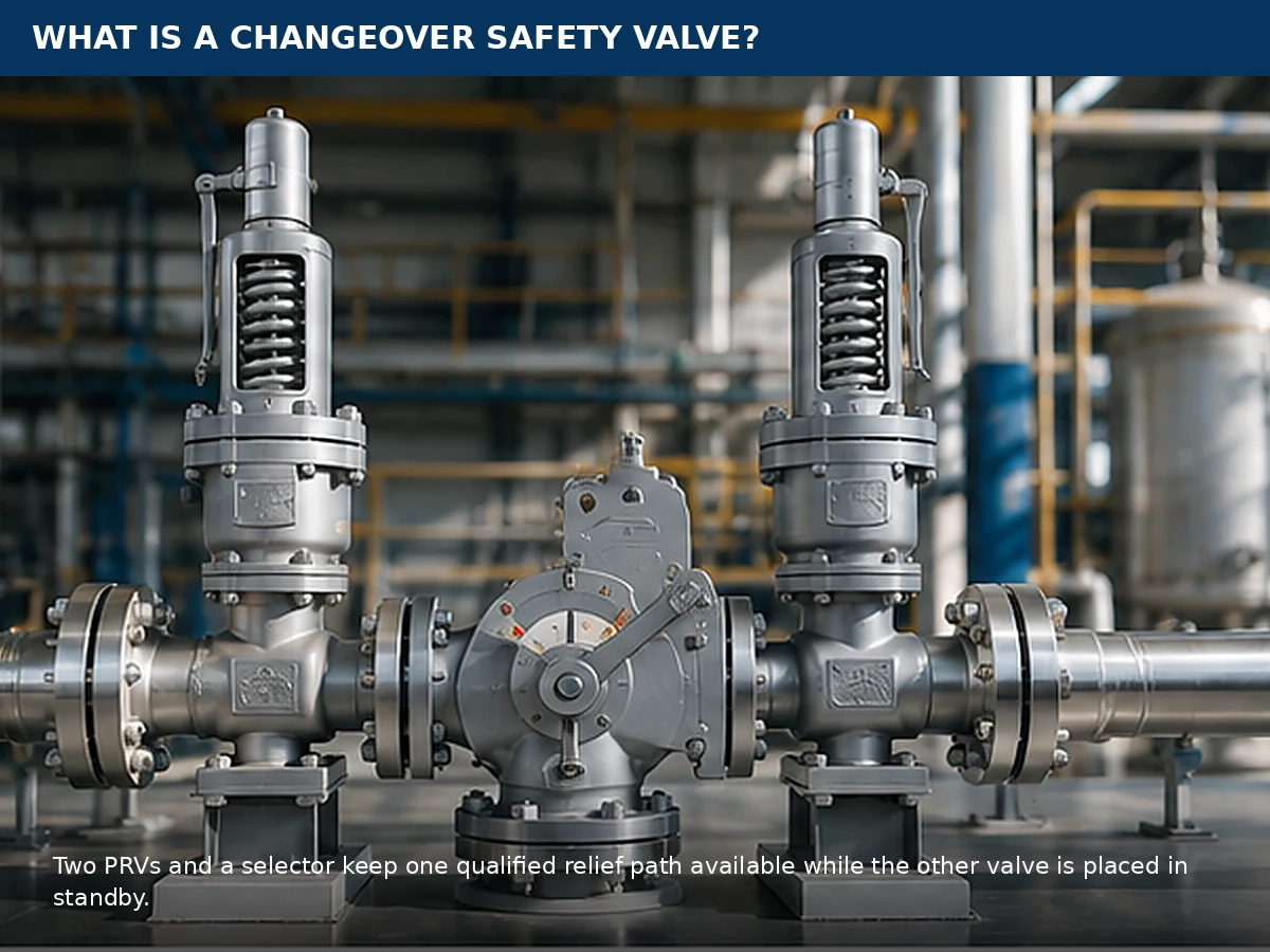
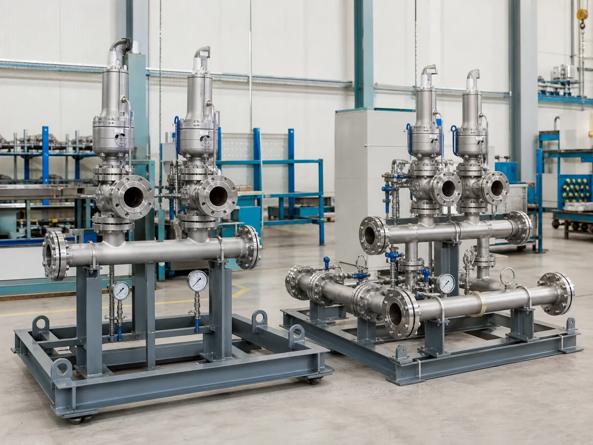
Conceptual industrial representation. Final product configuration must be confirmed from the selected manufacturer and project requirements.
Page boundary: this page explains the definition, components and duty/standby principle. Product configurations belong to the
changeover safety valves
product page. Detailed capacity, pressure-drop, back-pressure, materials and RFQ decisions belong to the separate PRV Changeover Valve Selection Guide.
Basic operating boundary
- Confirm the selected active PRV and open inlet/outlet path.
- Avoid positions that can leave both relief paths unavailable.
- Verify the standby branch pressure-free before maintenance.
What Is a Changeover Safety Valve?
A Simple Definition
A changeover arrangement connects two pressure relief valves to the same protected equipment through a controlled selector. In normal duty/standby service, one PRV is active and the other is isolated as the standby unit.
The standby valve may be serviced only where the system design, approved procedure and applicable requirements allow the equipment to remain in operation.
Changeover Valve, Selector Valve and PRV Terminology
The PRV responds to overpressure; the selector changes which PRV is connected. The complete arrangement also includes the inlet and outlet paths and operating controls.
Because the selector is part of the relief path, its internal position and flow characteristics must support the selected PRV.
Why Are Two Safety Valves Used?
Maintenance availability
The standby position can support planned inspection, testing, repair or replacement without automatically removing both PRVs from service.
Duty / standby control
One PRV is active and one is standby. The operating organization must control and record which path protects the equipment.
Capacity still requires proof
In duty/standby service, one active PRV may need to satisfy the assigned relief case independently.
Required capacity, selected orifice and documented or certified relieving capacity should be reviewed separately. See the safety valve sizing and certified capacity guide for the broader capacity relationship.
What Are the Main Parts of a Changeover Safety Valve System?
A typical arrangement includes two PRVs, an inlet selector, outlet paths, position controls and a method for depressurizing the standby branch where required.
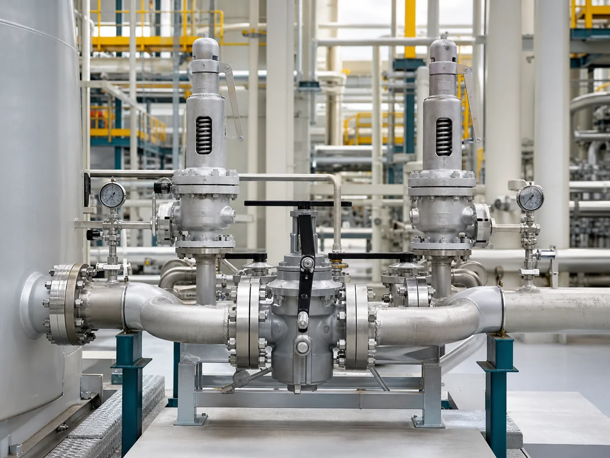
Simplified engineering illustration. Actual selector geometry and auxiliary features vary by manufacturer and project.
| Component | Basic function | What must be confirmed |
|---|---|---|
| Active PRV | Protects the equipment in the selected position | Set pressure, orifice, documented capacity, materials and current records |
| Standby PRV | Available for future duty or maintenance rotation | Suitability must be verified; it cannot be assumed from appearance or connection size |
| Inlet selector | Connects one PRV to the protected equipment | Internal flow path, resistance, travel, position and locking |
| Outlet selector, where applicable | Aligns the selected PRV with the discharge system | Position matching, back pressure and isolation integrity |
| Position indicator | Shows the intended selector position | Visibility and agreement with the actual internal position |
| Locking mechanism | Restricts unauthorized movement | Operating authority and final locked position |
| Bleed, vent or drain | Supports standby-side depressurization | Connection location, discharge handling and procedure |
| Inlet and outlet piping | Completes the relief path | Pressure loss, back pressure, supports, drainage and safe discharge |
What operating features can prove
Position indication and locking support operating control, but they do not prove capacity, a fully open internal passage or a pressure-free standby branch. Review the selector drawing, flow data, P&ID, PRV records and approved procedure.
How Does a Changeover Safety Valve Work?
Normal operating position
The selector connects the equipment to the active PRV while the standby PRV remains isolated.
Moving from Valve A to Valve B
Identify both PRVs, confirm the intended selector position and follow the approved procedure.
Confirming the new active path
Verify the selector position, lock, PRV identity and inlet/outlet alignment. Tandem selectors must correspond to the same PRV.
Isolating and depressurizing the standby side
The old active branch may retain pressure or liquid. Isolate it, vent or drain it safely and verify a zero-energy condition before maintenance.

Simplified sequence only. Actual operation must follow the manufacturer’s instructions and the approved site procedure.
| Stage | Active path | Standby side | Operator check |
|---|---|---|---|
| Normal operation | Valve A connected | Valve B isolated | Final position and lock |
| Before switching | Valve A active | Valve B prepared | Valve B identity and records |
| During switching | Flow path transferring | Unsafe simultaneous isolation must be avoided | Follow approved procedure |
| After switching | Valve B connected | Valve A isolated | Inlet and outlet alignment |
| Before maintenance | Valve B active | Valve A depressurized | Zero-energy verification |
| Return to service | Selected PRV active | Standby PRV available | Final position and documentation |
Active Relief Path Verification Matrix
Treat the final selector position as a complete pressure-protection path, not merely as a handle position.
| Verification point | Evidence to review | Failure if missed |
|---|---|---|
| Active PRV identity | Nameplate or asset ID, set-pressure record, orifice and documented capacity | The selected valve may not match the assigned relief case |
| Inlet continuity | Selector position, internal travel, branch alignment and inlet-piping condition | The PRV may be isolated or exposed to excessive inlet restriction |
| Outlet continuity | Outlet-selector position where used, discharge routing, drainage and header condition | Discharge may be blocked, misrouted or exposed to unresolved back pressure |
| Standby-side isolation | Isolation point, bleed or drain path and pressure indication | Personnel may encounter trapped pressure or hazardous media |
For broader piping, support, drainage and discharge considerations, review the safety valve installation guide.
Changeover Safety Valve vs Two Valves in Parallel
A duty/standby arrangement normally connects one PRV at a time. A parallel or staged system may keep multiple devices connected according to the relief calculation and operating philosophy.
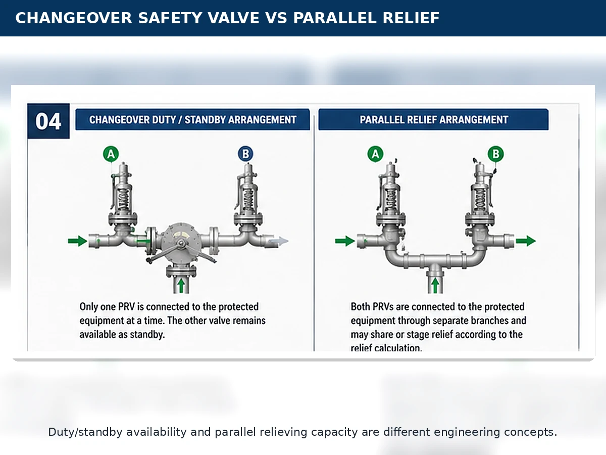
Conceptual comparison. The actual operating philosophy must be confirmed from the P&ID and relief basis.
| Question | Duty / standby changeover | Parallel or staged relief |
|---|---|---|
| Normal active valves | Usually one | One or more, according to the design |
| Main purpose | Maintenance availability | Required or staged relieving capacity |
| Capacity basis | Active PRV usually checked independently | Combined or staged basis defined by calculation |
| Selector | Normally part of the arrangement | May not be required |
| Key risk | Wrong or restricted active path | Incorrect capacity sharing or set-pressure coordination |
Important: valve count, connection size and set pressure do not prove relieving capacity. The relief scenario, required capacity, documented valve capacity and complete flow path must be reviewed.
What Changeover Configurations Are Common?
Inlet-only changeover
One inlet selector directs the protected equipment to one of two PRVs. Each PRV may discharge through a separate outlet arrangement where outlet-side selection is not required.
Tandem inlet and outlet switching
Coordinated inlet and outlet selectors keep the same active PRV connected to a closed discharge system. Both selector positions must match.
The outlet arrangement depends on the medium, discharge destination, common-header pressure, reverse-pressure risk, condensate, trapped media and maintenance plan. Detailed back pressure and bellows review may be required.
Simplified configuration diagram. Outlet switching depends on the actual discharge arrangement, back pressure and isolation requirements.
Configuration boundary
- Separate discharge paths may support inlet-only switching where the inactive outlet remains safe.
- A common closed header requires review of reverse pressure, superimposed back pressure and outlet isolation.
- Condensate, trapped media and drainage can change the acceptable arrangement.
- Tandem switching is a project decision, not a universal requirement.
Where Are Changeover Safety Valves Used?
Pressure vessels and process equipment
The arrangement may support planned PRV inspection where removing the only relief device would otherwise require the protected system to be safely taken out of service.
Compressor and gas skids
Compact packaged systems may use duty/standby PRVs where maintenance availability is important, but selector restriction, back pressure and trapped gas require review.
Continuous or campaign-based operation
A changeover arrangement may reduce the operational impact of planned PRV service, subject to the owner’s procedures and project requirements.
Planned PRV inspection programs
The greatest value appears when switching, isolation, depressurization and return-to-service controls are designed into the system from the start.
Application boundary: industry name alone does not justify a changeover arrangement. The protected equipment, relief scenario, medium and phase, required capacity, relieving temperature, back pressure, isolation method and maintenance philosophy must be reviewed for the actual installation.
What Can Go Wrong in a Changeover Arrangement?
Simultaneous isolation
A wrong or incomplete selector position can leave no qualified relief path.
Wrong selector position
An intermediate or undocumented position may not provide the intended flow area.
Excessive inlet restriction
Selector and inlet-piping restriction may contribute to unstable PRV operation.
Trapped pressure
The isolated branch can retain gas, vapor, liquid or condensate.
Mismatched inlet and outlet
Tandem selectors can block or misroute discharge when positions do not match.
Wrong replacement PRV
Matching flange size does not prove equivalent orifice, capacity or materials.
First checks: unstable lifting can indicate inlet restriction; standby-side pressure can indicate trapped volume, leakage or header pressure; difficult selector travel requires inspection rather than added force; and identical-looking PRVs still require identity, orifice, capacity and material verification.
What Should Be Checked Before Switching or Maintenance?
- Identify the active and standby PRVs.
- Verify the new active PRV against the current relief basis.
- Confirm inlet and outlet selector alignment.
- Follow the approved switching procedure.
- Lock and record the final selector position.
- Isolate, vent or drain the standby branch.
- Verify the branch is pressure-free.
- Confirm the correct PRV and records before return to service.
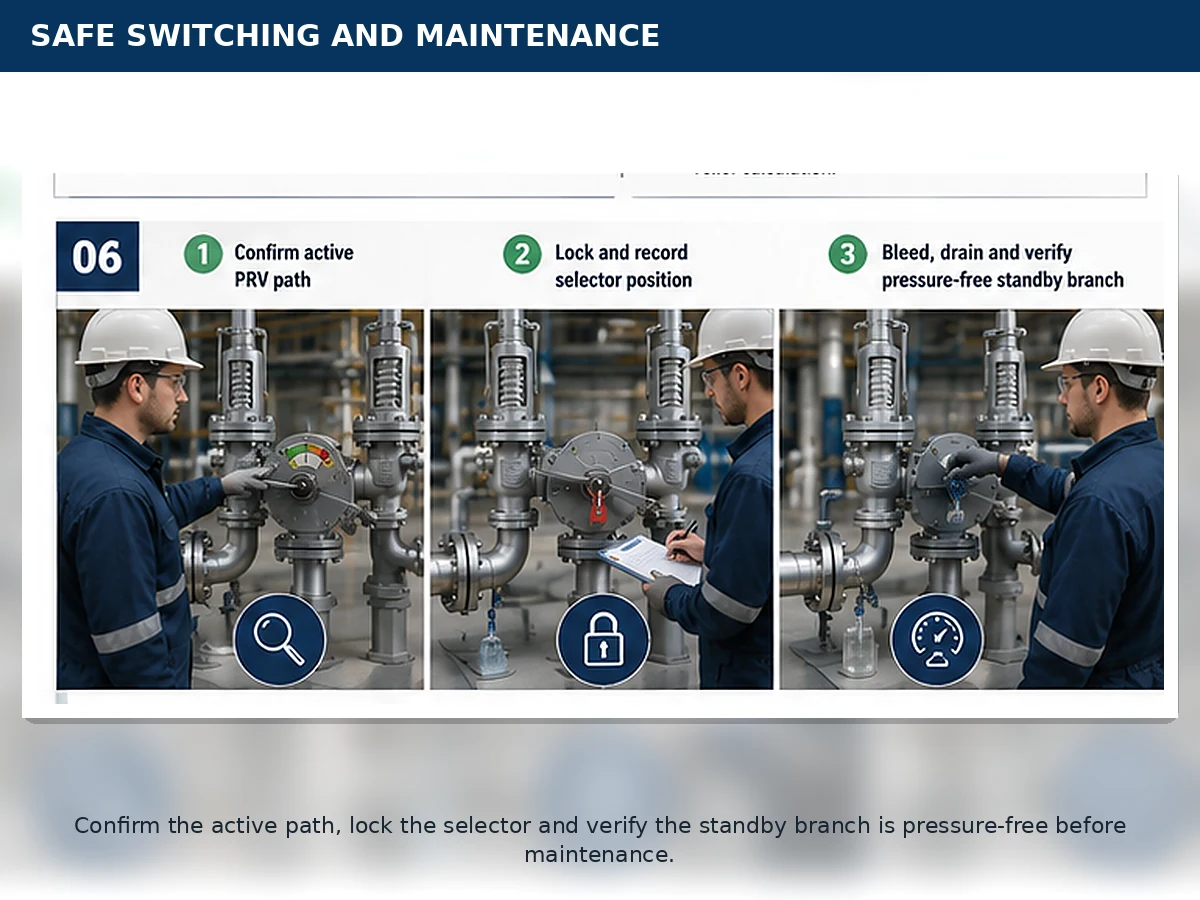
General planning illustration only. Site procedures, permits, LOTO and manufacturer instructions remain controlling.
Isolation and depressurization are different checks. Moving or locking the selector does not by itself prove that the standby branch is pressure-free.
Do
- Confirm the active path and final selector position.
- Use the designed bleed, vent or drain route.
- Record the operating position after switching.
Do not
- Remove a PRV because the handle appears to point away from it.
- Force a selector that does not travel normally.
- Use this article as the site operating procedure.
What Information Is Needed for Engineering Selection?
Formal selection should not begin from connection size alone. Confirm the protected equipment, governing relief scenario and complete active relief path.
- Protected equipment and governing relief scenario
- Medium, phase and relieving temperature
- Operating pressure, MAWP or design pressure, and set pressure
- Required relieving capacity and calculation basis
- PRV orifice and documented capacity
- Selector internal flow or resistance data
- Complete inlet and outlet piping
- Superimposed and built-up back pressure
- Materials, seats, seals and service compatibility
- Applicable code edition, project specification and documents
Input boundary: operating pressure, MAWP or design pressure, set pressure, required capacity, documented PRV capacity, inlet loss and back pressure are different engineering inputs.
The API 520 safety valve sizing guide supports sizing and selection interpretation, while the API 521 pressure relief systems guide provides broader relief-scenario and disposal-system context.
When Is a Changeover Safety Valve Not Enough?
It does not replace relief sizing
A selector cannot correct an undersized active PRV or an undefined required relieving rate.
It does not eliminate piping review
The selector, inlet branches, outlet branches and discharge header remain part of the pressure-protection path.
It does not replace operating controls
The system still requires switching, locking, isolation, depressurization and return-to-service procedures.
A changeover arrangement may be inappropriate where the capacity basis is unknown, selector flow data is unavailable, simultaneous isolation cannot be prevented, the discharge system is unresolved, material compatibility is unconfirmed or the application actually requires parallel or staged relief.
Do not proceed to final selection when:
- the relief scenario, required capacity or active PRV capacity is unknown;
- selector flow data, inlet loss or outlet back pressure remains unresolved;
- both paths can be isolated or the standby branch cannot be depressurized safely;
- medium, phase, temperature, materials or seals are unconfirmed; or
- the adopted code, project specification or local approval basis is unclear.
Composite Engineering Scenarios
Planned PRV inspection
Valve B becomes active before Valve A is isolated. Valve A still requires controlled depressurization before any connection is opened.
Lesson: switching, isolation and depressurization are separate steps.
Selector replacement
A replacement selector matches the flange size but has different internal flow geometry.
Lesson: connection size does not prove equivalent relieving performance.
Common closed header
The inlet selector is moved to Valve B, but the outlet selector must also correspond to Valve B.
Lesson: inlet and outlet selector positions must be verified as one operating system.
These are composite training scenarios, not customer projects or operating records.
Technical References and Application Boundary
- API 520 Part I — the 10th Edition has been published and provides sizing and selection guidance for pressure-relieving devices; verify the project-adopted edition.
- API Standard 521 — provides guidance for pressure-relieving and depressuring-system design; verify the project scope and adopted edition.
- ASME BPVC Section XIII — the official ASME page lists the 2025 edition and covers overpressure-protection devices, capacity and flow-resistance certification, installation and system design.
- ISO 4126-1 — ISO 4126-1:2013 was confirmed in 2025 and remains current; it is a product standard rather than an application standard.
Standards references support engineering interpretation and RFQ preparation. They do not imply that every ZOBAI product automatically carries every certification or is suitable for every jurisdiction.
Frequently Asked Questions
Is a changeover safety valve one valve or a complete system?
The phrase normally describes a complete arrangement consisting of two pressure relief valves, a selector or changeover mechanism, and the associated inlet and outlet piping. The selector is not itself the pressure relief valve.
Are both safety valves open at the same time?
In a conventional duty/standby arrangement, one PRV is normally connected to the protected equipment and the other is isolated. Parallel or staged arrangements may operate differently and must be identified from the P&ID and relief calculation.
Does a changeover arrangement provide double relieving capacity?
Not automatically. In a duty/standby arrangement, only one PRV may be active. That valve generally needs to satisfy the assigned relief case independently. Capacity must be verified from the required relieving rate and documented valve data.
Can the standby safety valve be removed while the equipment is operating?
Only where the system design, approved procedure, isolation method, depressurization method and applicable requirements permit it. The branch must be verified pressure-free before removal.
What prevents both relief paths from being closed?
The prevention method may involve internal selector geometry, mechanical travel, stops, locking, interlocking and operating procedures. It must be confirmed for the actual design rather than assumed from the product description.
Is an outlet changeover valve always required?
No. The need for outlet switching depends on the discharge arrangement, common-header pressure, reverse-pressure risk, medium migration, condensate and maintenance-isolation requirements.
What information is needed to select a changeover safety valve?
The review normally requires the protected equipment, relief scenario, medium and phase, operating pressure, MAWP or design pressure, set pressure, required capacity, relieving temperature, back pressure, piping, PRV data, selector data, materials and applicable documentation requirements.
Need Help Reviewing a Changeover Safety Valve Arrangement?
Send the available P&ID or piping sketch, protected equipment, relief scenario, pressure data, required capacity, medium and phase, relieving temperature, existing PRV datasheets, selector arrangement, inlet and outlet piping, back-pressure condition, material requirements and required documents.
Ask a Safety Valve Engineer