Engineering Selection Guide High Temperature Safety Valve Selection Guide Select from the governing relief scenario, not from a generic temperature label. Review relieving temperature, capacity, pressure-temperature rating, component exposure, back pressure, hot piping, testing, and documentation as one pressure-protection system. Relieving Temperature Capacity Basis Materials & Seat Back Pressure RFQ Data On this page Quick …

Engineering Selection Guide
High Temperature Safety Valve Selection Guide
Select from the governing relief scenario, not from a generic temperature label. Review relieving temperature, capacity, pressure-temperature rating, component exposure, back pressure, hot piping, testing, and documentation as one pressure-protection system.
Quick Answer: How Should You Select a High Temperature Safety Valve?
Select a high-temperature safety valve from the governing relief scenario, not from a generic temperature label. Confirm the protected equipment, medium and phase, operating pressure, MAWP or design pressure, set pressure, required relieving capacity and its basis, relieving temperature, superimposed and built-up back pressure, and the inlet and outlet piping arrangement.
Then verify the valve-body and flange pressure-temperature rating, selected orifice, documented or certified capacity, and the temperature exposure of every limiting component, including the seat, spring, bellows, gasket, seal, pilot and sensing system where fitted. Connection size, pressure class, body material, metal seat or open bonnet does not by itself prove suitability. If the scenario, capacity, relieving temperature or back-pressure data are missing, the final selection remains to be confirmed against manufacturer data, the project specification and the adopted code edition.
Product-family context: High Temperature Safety Valves.
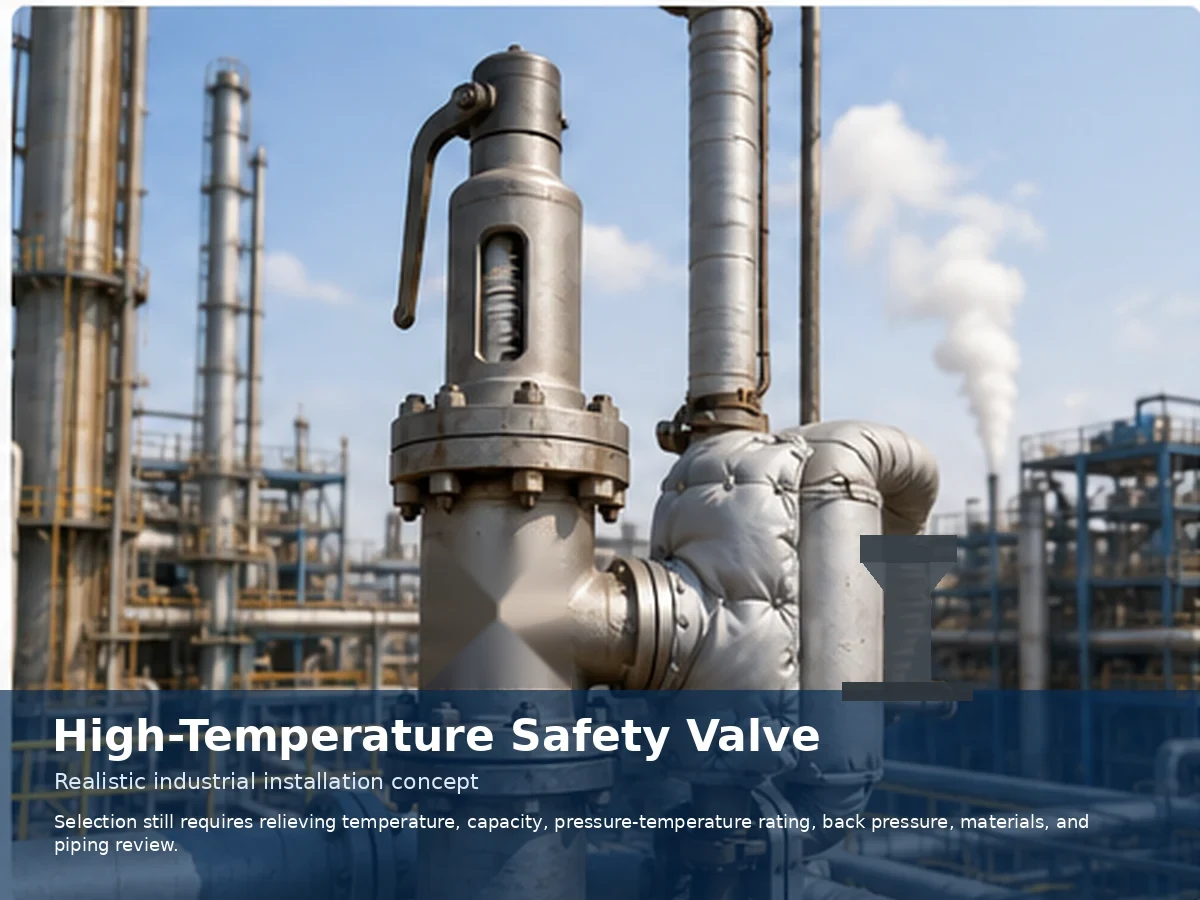
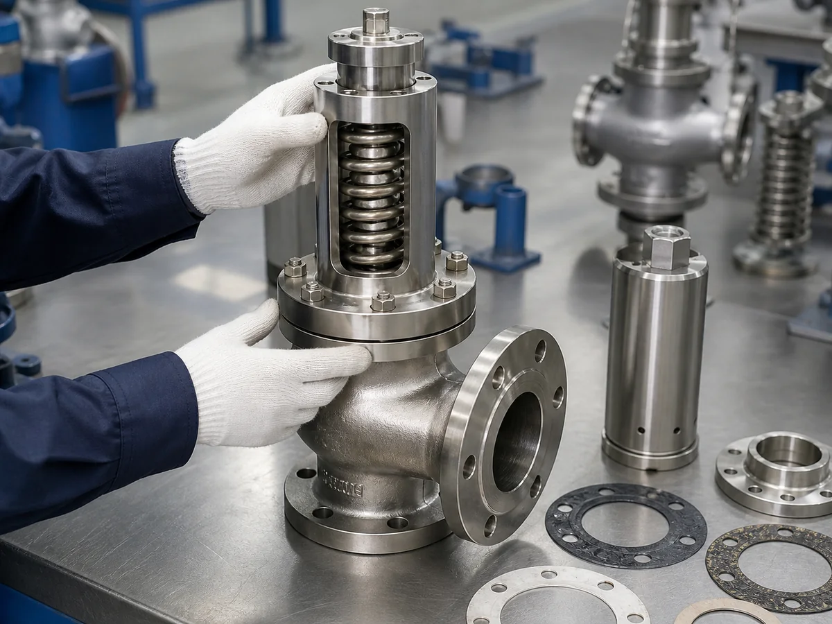
Realistic industrial visualization. Final valve configuration, materials, rating, and installation must be confirmed for the selected model and project.
What Counts as High Temperature Service for a Safety Valve?
There is no universal temperature cutoff for every safety valve. The service becomes temperature-critical when heat changes the capacity calculation, pressure rating, component suitability, set-pressure behavior, leakage risk, piping loads, or maintenance method. Continuous exposure and short relieving exposure must be reviewed separately because the highest fluid temperature may not be the longest component exposure.
| Trigger for High-Temperature Review | What Changes | Evidence Needed |
|---|---|---|
| Pressure-temperature derating becomes material | Allowable pressure of the body, flanges, bolting, or connected piping may decrease. | Material group, metal temperature, rating table, and adopted edition. |
| Relieving properties differ from normal operation | Density, compressibility, viscosity, flashing, or two-phase behavior can change the required area. | Scenario-specific relieving pressure, temperature, phase, and physical properties. |
| Internal components become limiting | Seat, guide, spring, bellows, gasket, seal, pilot, or sensing line may govern the assembly. | Selected-model component materials and manufacturer temperature limits. |
| Thermal cycling or heat soak is significant | Clearances, alignment, gasket loading, spring exposure, and external pipe loads can change. | Operating cycle, exposure duration, insulation boundary, and installation layout. |
| Discharge piping becomes a thermal-mechanical load | Expansion, reaction force, condensate, back pressure, and support can affect operation. | Outlet calculation, support concept, drainage, and common-header data. |
Continuous Exposure vs Relieving Exposure
A valve on a hot header may remain heat-soaked during normal operation without lifting. Another valve may stay relatively cool until a short upset sends a hotter fluid through the nozzle and outlet. The RFQ should identify both conditions, their duration, and expected cycling.
When a Generic “High Temperature” Label Is Not Enough
- Do not select by a catalog maximum temperature without confirming the exact series and configuration.
- Do not infer spring temperature from inlet-fluid temperature.
- Do not assume the highest-temperature scenario also controls relieving capacity.
- Do not use body material as proof that seats, gaskets, bellows, pilots, or seals are suitable.
- Do not approve a replacement from size, class, and appearance alone.
Which Temperature Should Be Used for Selection?
Use a temperature map rather than one undefined “maximum temperature.” The map should connect each relief scenario to the fluid temperature at the valve inlet, the expected body and flange metal temperature, and the probable spring-chamber or pilot-component exposure.
| Temperature Input | Engineering Use | Common Error |
|---|---|---|
| Operating temperature | Continuous heat exposure during normal service. | Using it as the only temperature in the RFQ. |
| Design temperature | Equipment or piping design boundary and rating review. | Substituting it automatically for relieving temperature. |
| Relieving temperature | Fluid properties, sizing, internal exposure, and discharge behavior for a named relief case. | Providing a value without identifying the scenario. |
| Body / flange metal temperature | Pressure-temperature rating of pressure-containing parts and connections. | Checking pressure class without material group and metal temperature. |
| Spring-chamber / bonnet temperature | Spring material, set-pressure correction, seals, guides, and long-term stability. | Assuming it equals the inlet-fluid temperature. |
| Ambient / external heat exposure | Fire case, radiant heat, weather, insulation, or local thermal environment where applicable. | Ignoring external heat or blocked ventilation. |
Minimum Temperature Map for the Datasheet
- Name each credible relief scenario and identify which case controls capacity.
- State operating, design, and relieving temperature as separate fields.
- Identify whether the fluid is steam, gas, vapor, liquid, or two-phase at relief conditions.
- State expected exposure duration and thermal-cycle frequency.
- Mark body-metal and spring-chamber temperature as measured, calculated, estimated, or to be confirmed.
- Identify insulation, heat tracing, jackets, fire exposure, and hot common headers.
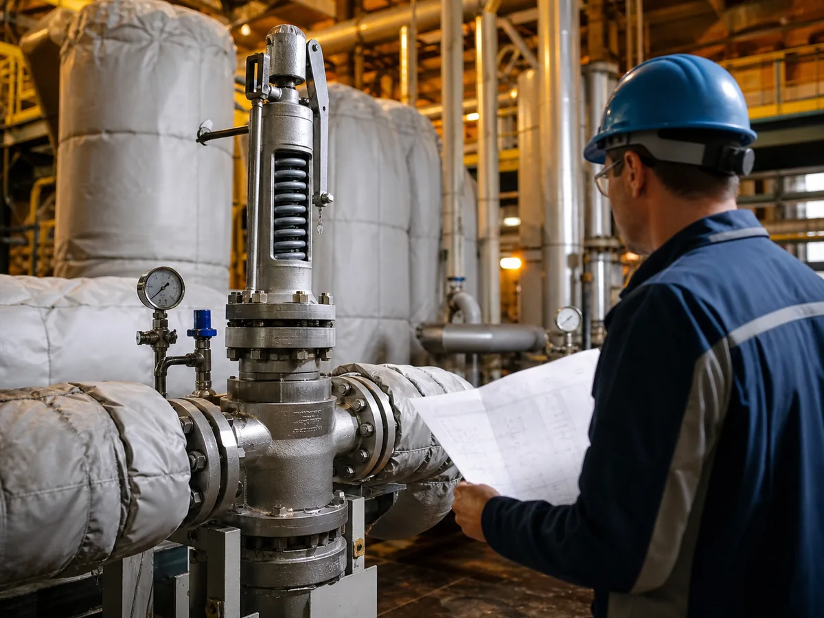
Simplified engineering illustration. Actual component temperatures depend on the valve design, installation, insulation, relief scenario, and manufacturer data.
High Temperature Safety Valve Selection Workflow
The workflow is sequential. A supplier can offer a preliminary configuration with incomplete information, but the result must remain clearly marked as provisional until the missing inputs are confirmed. Use the API 521 pressure relief systems guide when defining relief scenarios, disposal systems, flare or vent context, and depressuring interfaces within its applicable scope.
| Step | Decision | Minimum Input | Stop / Confirm Condition |
|---|---|---|---|
| 1 | Define protected equipment and relief scenario | P&ID, protected boundary, scenario description | Boundary or credible case unclear |
| 2 | Confirm medium and phase | Composition and relief-state phase | Two-phase, reactive, coking, or corrosive behavior undefined |
| 3 | Confirm pressure and capacity basis | Operating pressure, MAWP/design pressure, set pressure, required rate | No approved capacity calculation |
| 4 | Establish governing relieving temperature | Scenario-specific pressure, temperature, and properties | Only normal operating temperature supplied |
| 5 | Check pressure-temperature rating | Material group, class/PN, metal temperature, rating standard | Rating cannot be demonstrated |
| 6 | Screen components and configuration | Body, trim, seat, spring, bonnet, bellows/pilot/seals | Any limiting component unverified |
| 7 | Review inlet, outlet, and back pressure | Pressure-loss, back-pressure, support, drainage, thermal-growth data | Stability or mechanical loads not evaluated |
| 8 | Confirm tests and documents | Test basis, capacity evidence, drawings, material records, approvals | Required evidence not agreed |
Preliminary Selection Matrix
| Observed Condition | Possible Direction for Review | What It Does Not Prove |
|---|---|---|
| High or variable outlet back pressure | Review balanced-bellows or pilot-operated options where allowed by model limits. | That either design is automatically suitable at the required temperature. |
| Hot steam with spring exposure concern | Review bonnet arrangement, spring-chamber temperature, drainage, and applicable boiler/vessel rules. | That an open bonnet is mandatory. |
| Viscous, coking, or solidifying liquid | Review liquid capacity, deposits, drainage, tracing, or jacket needs. | That every thermal-oil valve requires a jacket. |
| Tight leakage requirement | Define seat construction and the required seat-tightness test. | That a metal seat provides zero leakage. |
| Replacement with limited records | Reconstruct the original design basis before selecting an equivalent. | That matching dimensions or pressure class establishes equivalence. |
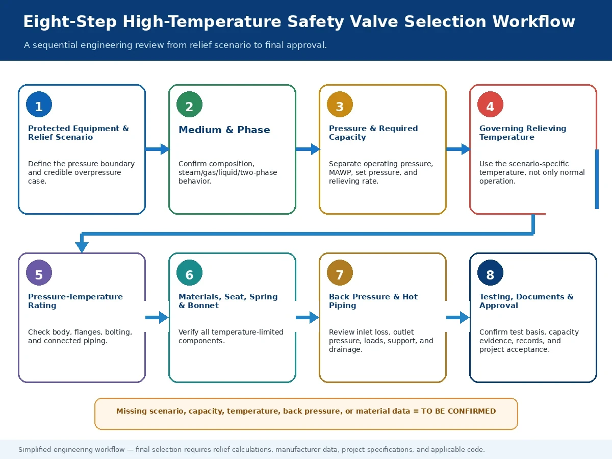
Simplified engineering workflow. Final selection requires the actual relief calculation, manufacturer data, project specification, applicable code edition, and local requirements.
Check Pressure-Temperature Rating and Required Relieving Capacity
Rating reference: Pressure-Temperature Ratings.
Capacity reference: Safety Valve Sizing and Certified Relieving Capacity.
Sizing-method context: API 520 sizing workflow for translating the applicable sizing and selection basis into RFQ inputs; the project must still confirm the adopted edition, scope, and exact valve data.
Rating and capacity are separate checks. Use the applicable flange standard to verify flanges and flanged fittings within that standard’s stated scope. Verify the valve-body and complete assembly pressure-temperature limits from the selected valve design basis and manufacturer data. Relieving capacity is a separate question: it concerns the amount of fluid the exact valve configuration can discharge under the approved scenario basis.
Pressure Terms That Must Remain Separate
| Term | Engineering Meaning | Selection Boundary |
|---|---|---|
| Operating pressure | Normal system pressure during intended operation. | Does not establish set pressure, MAWP, or relieving capacity. |
| Design pressure | Pressure used as part of the equipment or piping design basis. | Must not be treated automatically as MAWP or relieving pressure. |
| MAWP | Maximum allowable working pressure of the protected equipment at the governing temperature, as defined by the applicable design basis. | Belongs to the protected equipment; it is not a valve-capacity value. |
| Set pressure | Specified inlet pressure at which the safety valve is set to begin opening under the applicable test or service basis. | Does not prove the required or documented relieving capacity. |
| Overpressure | Pressure increase above set pressure while the valve is relieving. | Use the applicable project and code basis; do not assume a universal percentage. |
| Relieving pressure | Valve-inlet pressure used with the approved relief scenario for sizing and capacity verification. | Must be tied to the medium, phase, relieving temperature, and scenario assumptions. |
| Accumulation | Pressure increase above the protected equipment’s MAWP during an overpressure event. | Relates to the protected system and is not interchangeable with valve overpressure. |
| Blowdown / reseat pressure | Difference between set pressure and reseating pressure, or the pressure at which the valve closes after opening. | Depends on valve design, service, adjustment limits, and the applicable acceptance basis. |
| Item | Required Engineering Question | Evidence to Accept |
|---|---|---|
| Required relieving rate | What mass or volumetric flow must the system relieve in the controlling case? | Approved relief calculation and physical-property basis. |
| Required area | What area follows from the applicable sizing method and scenario inputs? | Calculation sheet with pressure, temperature, medium, phase, and correction basis. |
| Selected orifice | Does the chosen orifice meet or exceed the required area without relying on connection size? | Manufacturer orifice data for the exact model. |
| Documented / certified capacity | Does the selected valve configuration provide the required capacity at the stated conditions? | Applicable manufacturer capacity documentation and project-required certification basis. |
| Pressure-temperature rating | Can the body, inlet/outlet flanges, bolting, gasket, and connected piping carry pressure at metal temperature? | Material group and adopted pressure-temperature rating source. |
| Back-pressure effect | Does outlet pressure alter capacity, opening, stability, or blowdown? | System calculation and selected-model back-pressure limits. |
DN/NPS, inlet size, outlet size, Class, PN, body material, and external dimensions do not by themselves establish relieving capacity.
Capacity Review Before Replacement
Compare the original required capacity, selected orifice, set pressure, allowed overpressure, medium, relieving temperature, and back pressure with the proposed replacement. Where original calculations or capacity records are unavailable, the replacement remains an engineering reassessment—not a like-for-like purchase.
Select Body, Trim, Seat, Spring, Bellows, and Sealing Materials
Treat the valve as an assembly. The lowest verified component limit can govern even when the body material and pressure class appear acceptable.
| Component | High-Temperature Screening | Confirmation Required |
|---|---|---|
| Body / bonnet / flanges | Allowable stress, oxidation, corrosion, thermal cycling, and pressure-temperature rating. | Exact material specification, metal temperature, class/PN, and model limit. |
| Nozzle / disc / spindle / guide | Distortion, erosion, corrosion, deposits, differential expansion, and galling. | Trim combination, hardness or surface treatment where applicable, and fluid compatibility. |
| Seat | Actual seat temperature, leakage requirement, contamination, cycling, and fire/upset exposure. | Metal or soft-seat construction, test medium, test pressure, and acceptance criterion. |
| Spring | Actual spring-chamber temperature, relaxation risk, adjustment range, and set-pressure correction. | Spring material, manufacturer temperature basis, and test procedure. |
| Bellows — if fitted | Temperature, pressure, corrosion, fatigue, venting, and back-pressure duty. | Bellows material, cycle basis, vent arrangement, and model limits. |
| Pilot / seals / sensing line — if fitted | Seal, diaphragm, piston, tubing, condensation, plugging, or heat-tracing limits. | Exact pilot system and all temperature-limited components. |
| Gaskets / packing / seals | Thermal degradation, extrusion, leakage, and medium compatibility. | Actual component temperature and approved material. |
Metal Seat vs Soft Seat
A metal seat is often reviewed for elevated temperature, but it does not mean zero leakage. A soft seat may be acceptable only where the exact material, seat temperature, pressure, medium, cycling, and manufacturer limit are verified. The purchase specification should define the required API 527 seat tightness test or other project-approved test method, test medium, pressure, and acceptance basis rather than relying on a generic seat description.
Material Selection Stop Conditions
- The composition or phase at relief conditions is unknown.
- The selected model’s spring, seal, bellows, or pilot limits are unavailable.
- The fluid can coke, polymerize, crystallize, corrode, or deposit solids and no cleaning strategy is defined.
- Body/flange rating is checked, but trim and gasket materials remain unspecified.
- A product-family temperature range is being applied to an unconfirmed individual model.
Simplified engineering illustration, not a certified manufacturing drawing. Component arrangement varies by valve design.
Choose the Valve Configuration for the Medium and Service
Temperature narrows the acceptable designs, but the medium, phase, operating margin, back pressure, leakage requirement, maintenance method, and code scope determine the configuration review.
For saturated or superheated steam product-family context, review steam safety valves; the final bonnet, lever, trim, spring, capacity, and test basis remain model- and project-specific.
| Service | Primary Selection Inputs | Configuration Questions | Do Not Assume |
|---|---|---|---|
| Saturated / superheated steam | Steam capacity, relieving temperature, code scope, drainage, spring exposure, reaction force. | Bonnet, lever, trim, discharge arrangement, and test basis. | Open bonnet or one steam-valve design is mandatory for every case. |
| Hot gas / vapor | Composition, compressibility, relieving temperature, flare/header back pressure, toxicity and disposal. | Conventional, balanced, or pilot-operated design within model limits. | Pilot-operated automatically means better high-temperature performance. |
| Thermal oil / hot liquid | Liquid capacity, viscosity, flashing, coking/deposits, blocked-in thermal expansion, drainage. | Liquid trim, seat, collection system, tracing or jacket only where justified. | Every hot liquid requires a jacketed valve. |
| Two-phase / reactive service | Approved scenario method, phase split, reaction heat, deposits, discharge system. | Model-specific stability, materials, and disposal-system review. | A generic gas or liquid selection method is sufficient. |
When Not to Select by Temperature Alone
- Variable back pressure may govern the choice between conventional, balanced, and pilot-operated designs.
- Toxic or flammable media may govern bonnet, vent, packing, and discharge containment.
- Viscous or deposit-forming liquids may govern drainage, tracing, cleaning, and inlet layout.
- Boiler, vessel, or piping jurisdiction may govern construction, lever, testing, and documentation.
- Frequent cycling may govern guides, springs, gaskets, bellows, and inspection intervals.
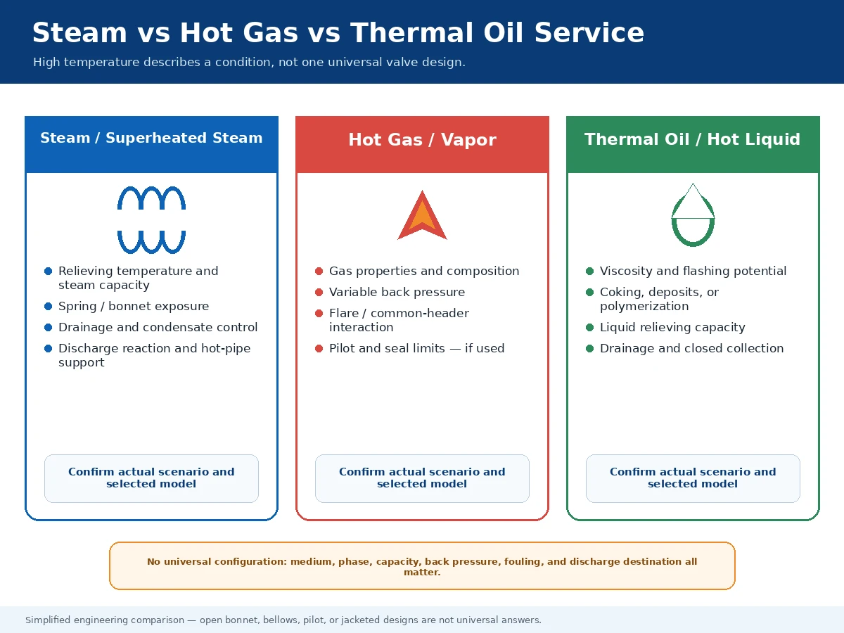
Simplified engineering comparison. Final configuration depends on the actual medium, relief scenario, project code, and manufacturer model limits.
Review Back Pressure, Inlet Loss, and Hot Discharge Piping
Related engineering guide: Back Pressure and Bellows.
A thermally suitable valve can still be unstable, undersized, or mechanically overloaded when the inlet and outlet systems are not reviewed as part of the relief path.
For inlet routing, outlet support, drainage, orientation, vents, and safe discharge review, use the Safety Valve Installation Guide.
| Observed Condition | Engineering Effect | Required Action |
|---|---|---|
| Superimposed back pressure before opening | Can change effective opening conditions and conventional-valve suitability. | State normal and maximum values and whether they are constant or variable. |
| Built-up back pressure during discharge | Can affect capacity, stability, blowdown, and outlet loading. | Calculate at required flow and compare with exact model limits. |
| Common discharge header | Other devices can create variable pressure and interaction. | Provide simultaneous-relief assumptions and header calculation. |
| Excessive inlet pressure loss | Can reduce valve-inlet pressure during flow and promote instability or chatter. | Calculate the inlet loss for the required flow using the applicable project basis. |
| Hot outlet thermal growth | Can impose bending, flange, and nozzle loads on the valve. | Provide independent support, flexibility, and reaction-force review. |
| Condensate or trapped liquid | Can add back pressure, corrosion, water hammer, freezing, or unsafe discharge. | Define drainage, low points, venting, and safe collection. |
| Insulation around bonnet, vents, or pilot | Can raise component temperature or block required openings. | Confirm the manufacturer-approved insulation boundary. |
Installation Do / Do Not
| Do | Do Not |
|---|---|
| Keep the inlet direct and sized from the pressure-loss calculation. | Reduce or lengthen the inlet without checking stability and capacity. |
| Support heavy outlet piping independently. | Use the valve body as a pipe anchor. |
| Provide thermal flexibility and discharge-reaction support. | Force flange alignment or transfer expansion loads into the valve. |
| Provide drainage and protect required vents. | Trap condensate or cover bonnet/bellows vents with insulation. |
| Confirm safe discharge and personnel protection. | Route hot discharge toward walkways, platforms, or maintenance areas. |
What Can Go Wrong in High Temperature Service?
Failure symptoms should be traced back to the relief scenario, capacity, temperature map, materials, back pressure, and installation—not treated as isolated valve defects.
| Symptom or Risk | Possible Cause | First Engineering Check |
|---|---|---|
| Valve chatters or cycles during relief | Inlet pressure loss, excessive/variable back pressure, oversized valve, or unsuitable operating margin. | Inlet/outlet calculations, required capacity, selected orifice, and model stability limits. |
| Seat leakage increases after hot service | Thermal distortion, deposits, erosion, contamination, or test requirement mismatch. | Seat condition, fluid cleanliness, actual seat temperature, and specified tightness basis. |
| Set pressure shifts | Spring-chamber temperature, spring relaxation, incorrect correction, friction, or poor calibration. | Spring temperature, manufacturer correction method, test records, and guide condition. |
| Bonnet, pilot, or seals overheat | Insulation boundary, heat conduction, hot ambient, leakage, or sensing-line exposure. | Component temperature map and manufacturer limits. |
| Flange leakage or body distortion | Pressure-temperature rating mismatch, gasket/bolting issue, forced alignment, or thermal pipe load. | Rating, bolting, gasket, supports, and piping stress. |
| Replacement does not match capacity | Selection based on size, class, or appearance rather than relief basis. | Required capacity, original orifice, documented capacity, medium, and relief conditions. |
| Bellows or pilot reliability concern | Temperature, corrosion, fouling, vent blockage, fatigue, or unsuitable back-pressure duty. | Exact component materials, cycle, vent/sensing arrangement, and model limitations. |
Composite Engineering Scenarios for Training
These are hypothetical combinations used to explain the decision logic. They are not customer projects, field results, capacity evidence, certification records, or proof that a particular ZOBAI model is suitable.
| Composite Training Scenario | Controlling Questions | Required Evidence |
|---|---|---|
| Superheated steam header | Which code scope applies? Which case controls capacity? What relieving and spring-chamber temperatures apply? What drainage, reaction, and support are required? | Steam relief calculation, set/overpressure basis, temperature map, material/rating review, discharge layout, and test requirements. |
| Thermal-oil loop | Is the case thermal expansion, blocked outlet, or another upset? What are viscosity, flashing, coking, seat-leakage, and collection requirements? | Liquid relief basis, properties at relief conditions, material compatibility, drainage, tracing/jacket justification, and outlet-system data. |
| Hot process gas or reactor | Is the relief gas, vapor, or two-phase? Is the fluid reactive, polymerizing, corrosive, or connected to a variable-back-pressure flare header? | Approved process calculation, composition/phase, relieving pressure and temperature, back-pressure profile, selected-model limits, and disposal-system data. |
Scenario Review Template
- Define the protected equipment and pressure boundary.
- Name the credible overpressure case and identify the controlling case.
- Confirm medium, phase, composition, relieving pressure, and relieving temperature.
- Verify required capacity and selected-valve capacity basis.
- Screen component materials and valve configuration.
- Review inlet loss, back pressure, discharge loads, drainage, and safe disposal.
- Define testing, documents, approval, and installation responsibilities.
High Temperature Safety Valve RFQ Checklist
A complete RFQ allows the supplier to distinguish preliminary screening from a final engineering selection and reduces the risk of hidden assumptions.
| Data Group | Minimum Information | Why It Is Required |
|---|---|---|
| Protected equipment and scenario | Equipment tag, protected boundary, scenario description, P&ID. | Defines what the valve protects and what drives flow. |
| Medium and phase | Composition, steam/gas/vapor/liquid/two-phase state, corrosive or deposit-forming behavior. | Controls sizing, materials, seat, drainage, and discharge. |
| Pressure and capacity | Operating pressure, MAWP/design pressure, set pressure, allowed overpressure, required capacity and basis. | Separates pressure settings from required flow. |
| Temperature | Operating, design, relieving, body-metal, spring-chamber, ambient/fire exposure where applicable. | Supports sizing, rating, and component review. |
| Back pressure and piping | Superimposed/built-up back pressure, inlet/outlet connections, pressure loss, support, drainage, discharge destination. | Supports stability, capacity, and mechanical integration. |
| Materials and configuration | Body, trim, seat, spring, bellows/pilot, gasket/seal, bonnet, lever, insulation boundary. | Identifies temperature- and medium-limited components. |
| Testing and documents | Set-pressure test, temperature correction, seat test, material records, capacity basis, drawings, nameplate, ITP, code/edition. | Defines acceptance evidence before release. |
Testing and Documentation Matrix
| Document / Test | Purpose | Buyer Should Confirm |
|---|---|---|
| Relief calculation | Defines required rate, area, pressure, temperature, phase, and assumptions. | Approved scenario and capacity basis. |
| Capacity documentation | Shows selected-valve performance basis. | Exact model, orifice, medium, pressure, temperature, and required certification scope. |
| Set-pressure / CDTP record | Connects workshop calibration to service conditions where correction is required. | Manufacturer method, test medium, and acceptance. |
| Seat-tightness test | Defines leakage test method and acceptance. | Applicable standard, test pressure, medium, seat type, and project criterion. |
| Material records | Verifies pressure-containing and specified internal materials. | Required document type, heat/lot traceability, and scope. |
| Drawing / BOM / nameplate | Verifies configuration, dimensions, materials, markings, and installation interfaces. | Consistency with datasheet and purchase order. |
| Installation and maintenance instructions | Defines orientation, support, vents, drainage, adjustment, inspection, and retest. | Exact selected series and revision. |
Replacement Verification Workflow
- Collect the existing nameplate, datasheet, model, serial number, test records, and installation photographs.
- Recover the protected equipment, relief scenario, required capacity, and original code basis.
- Compare set pressure, orifice, documented capacity, relieving temperature, back pressure, materials, seat, bonnet, bellows/pilot, and connections.
- Check dimensional and piping compatibility without treating it as proof of hydraulic equivalence.
- Document all differences and obtain engineering approval before purchase or installation.

Conceptual checklist. Final data fields depend on the project, applicable code, selected valve design, and local regulatory requirements.
Technical References
These official sources support the engineering framework. The edition check below was completed on 3 August 2026. The project must still verify the adopted edition, scope, jurisdiction and acceptance criteria. A standard name does not prove that a specific ZOBAI valve is certified or approved for a particular service.
- API 520 Part I API identifies Part I, 10th edition, as the published sizing and selection standard for pressure-relieving devices within its stated scope; verify the project-adopted edition.
- API Standard 521 API’s current standards plan lists API 521, 7th edition, for pressure-relieving and depressuring systems; verify the adopted edition and project scope.
- ASME BPVC Section XIII Official ASME page for the 2025 edition covering overpressure protection of boilers, pressure vessels and piping systems within its stated scope.
- ASME B16.5 Official ASME page for the 2025 edition covering pressure-temperature ratings, materials, dimensions and testing for flanges and flanged fittings within its scope—not the complete safety-valve assembly.
- ISO 4126-1 ISO 4126-1:2013 was reviewed and confirmed in 2025 and remains current; it is a safety-valve product standard, not an application code for the protected system.
- API 527 API’s current standards plan lists API 527, 5th edition, for seat tightness of pressure relief valves; verify the adopted edition, test medium, pressure and acceptance basis.
- National Board Temperature Considerations National Board technical guidance explains that manufacturer literature is required for design temperature limits and correction factors, and that capacity must be evaluated at actual service conditions.
Frequently Asked Questions
01 What temperature is considered high temperature for a safety valve?
There is no universal cutoff for every safety valve. A high-temperature review is required when temperature changes fluid properties, pressure-temperature rating, component limits, set-pressure behavior, leakage risk, piping loads, or maintenance. Confirm the actual relief scenario and selected model.
02 Should a safety valve be selected using operating temperature or relieving temperature?
Both may be required. Operating temperature describes continuous exposure, while relieving temperature describes the fluid condition for a named overpressure scenario and is a key sizing and selection input. Body-metal and spring-chamber temperatures may also need separate review.
03 Is a metal seat always required for high-temperature service?
No. A metal seat is frequently considered at elevated temperature, but the decision depends on actual seat temperature, medium, pressure, leakage requirement, deposits, cycling, and manufacturer data. A metal seat does not mean zero leakage.
04 Is an open bonnet required for every high-temperature safety valve?
No. Open, closed, packed, or extended bonnet arrangements depend on spring exposure, medium containment, venting, code scope, ambient conditions, and manufacturer design. Temperature alone does not make an open bonnet mandatory.
05 Can the same pressure class be used as temperature increases?
Not automatically. Pressure-temperature ratings depend on material group, metal temperature, applicable standard, and edition. Check the body, inlet/outlet flanges, bolting, gasket, and connected piping at the governing condition.
06 How does back pressure affect a high-temperature safety valve?
Back pressure can affect opening, capacity, stability, blowdown, and outlet loading. Confirm superimposed and built-up values, whether they are constant or variable, common-header effects, and the selected model’s documented limits.
07 What information is required for a high-temperature safety valve quotation?
Provide the protected equipment, relief scenario, medium and phase, operating pressure and temperature, MAWP/design pressure, set pressure, required capacity and basis, relieving temperature, back pressure, connections, materials, seat, spring/bonnet/bellows or pilot requirements, piping data, code/edition, tests, and documents.
Engineering review
Send Your Operating Conditions for Engineering Review
Send the relief calculation, datasheet, P&ID, medium and phase, pressure definitions, required capacity, relieving temperature, back pressure, connections, materials, testing, and documentation requirements. Missing critical inputs will be returned as to be confirmed.