High-Temperature Safety Valve Engineering Insulation can change how heat moves through a high-temperature safety valve. The correct boundary may include the inlet and part of the body while keeping the bonnet, spring housing, lever, vents, drains, nameplate and maintenance joints accessible. Final coverage depends on the selected valve design, service conditions, manufacturer data and project …

High-Temperature Safety Valve Engineering
Insulation can change how heat moves through a high-temperature safety valve. The correct boundary may include the inlet and part of the body while keeping the bonnet, spring housing, lever, vents, drains, nameplate and maintenance joints accessible. Final coverage depends on the selected valve design, service conditions, manufacturer data and project requirements.
Thermal boundary
Bonnet and spring exposure
Vents and drains
Maintenance access
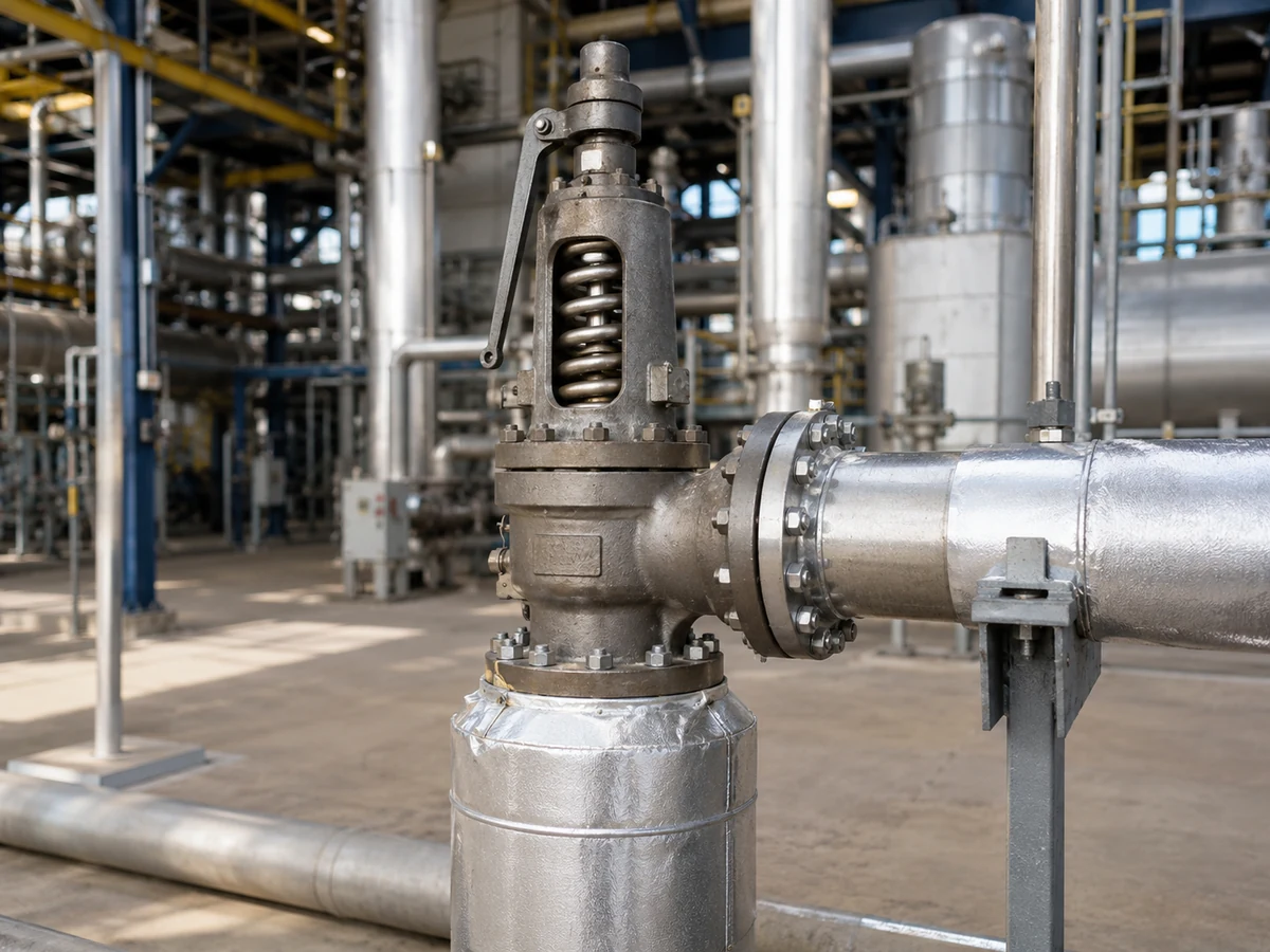
Conceptual industrial scene. Final insulation coverage must follow the selected valve design, manufacturer data and project specification.
Quick answer: From a pressure-protection perspective, insulation is an installed thermal-boundary decision—not a valve-capacity decision. It can increase the temperature exposure of the body, bonnet, spring, guide, spindle, bellows, seals and adjacent components, while also changing inspection access, drainage and corrosion-under-insulation risk. Body insulation is not the same decision as bonnet or spring-housing insulation. Do not cover vents, drains, lifting mechanisms, identification or maintenance joints unless the selected valve and project instructions explicitly permit it. Before construction, confirm the protected equipment, governing relief scenario, medium and phase, operating and relieving temperatures, pressure data, required capacity, back pressure, valve configuration, piping and manufacturer limits.
What an Insulation Review Can—and Cannot—Establish
An insulation review can identify thermal exposure, access, drainage and maintenance risks. It cannot independently prove that the selected valve protects the governing relief case.
| Question | Can insulation review answer it? | Separate evidence required |
|---|---|---|
| Where should insulation stop? | Yes, after the valve design, vents, drains, lever and maintenance access are reviewed. | Approved GA, installation detail and manufacturer instructions |
| Will the spring or seals see a different temperature? | It can identify the risk, but not a precise component temperature without supporting data. | Manufacturer thermal limits or project thermal assessment |
| Is the set pressure correct? | No. Insulation condition alone does not prove set-pressure accuracy. | Applicable test procedure, calibration data and model-specific correction basis |
| Is the relieving capacity adequate? | No. Set pressure, connection size and insulation coverage do not prove capacity. | Governing relief calculation and manufacturer-certified or documented capacity |
| Is the valve stable with the installed piping? | Only partially. Insulation may affect temperature or access, but stability also depends on sizing, inlet loss and back pressure. | Installed-system review, inlet/outlet calculations and valve configuration |
| Is the material suitable? | No. Insulation can change exposure, but material suitability covers all pressure-retaining and temperature-sensitive parts. | Body, trim, spring, bellows, seat, seal and gasket review |
Main selection risk: a visually neat insulation detail can still conceal an undersized valve, an unsuitable seat or spring, excessive back pressure, an incorrect bonnet treatment or an inaccessible maintenance joint.
Why Insulation Changes the Valve’s Thermal Boundary
Thermal insulation reduces heat transfer from a hot surface to the surrounding environment. When insulation is extended from process piping onto a safety valve, heat that would otherwise dissipate from the inlet neck, body or bonnet can travel farther through the valve assembly.
The process temperature shown on a datasheet is not necessarily the temperature experienced by every component. The body, nozzle, disc, guide, spindle, gasket, spring, bellows and bonnet can operate at different temperatures. Their actual exposure depends on conductive heat transfer, ambient cooling, operating duration, thermal cycling, bonnet design, insulation coverage and whether the valve sees continuous hot service or only short relieving events.
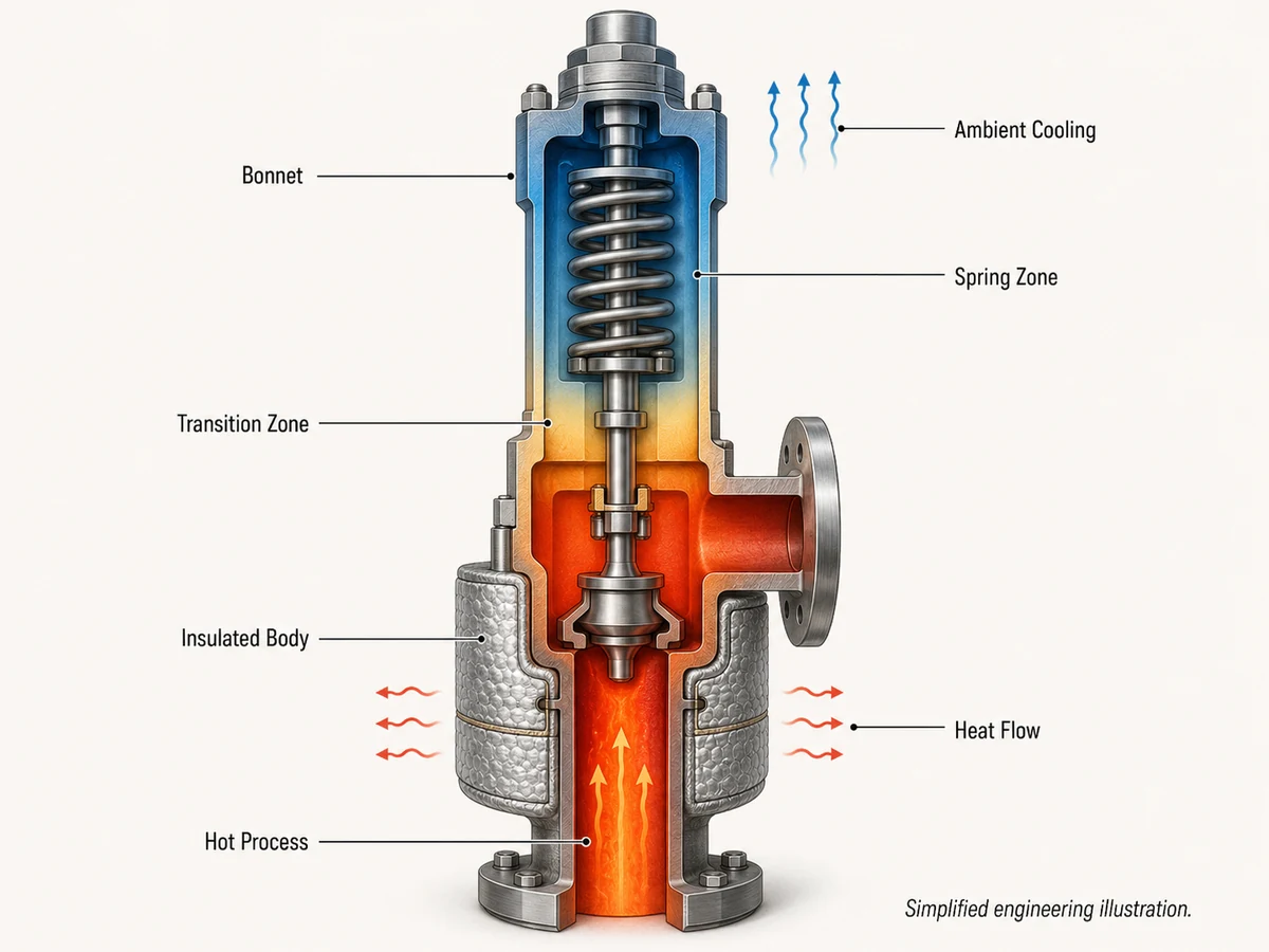
Simplified engineering illustration. Arrows indicate qualitative heat-transfer paths, not calculated component temperatures.
Medium Temperature Is Not the Same as Spring Temperature
A high-temperature medium may be separated from the spring by the disc, spindle, guide, bonnet geometry and ambient airflow. In other arrangements, continuous heat soak or heavy insulation can increase the temperature of the upper assembly. Do not copy the process-fluid temperature into the spring-temperature field without model-specific support.
The selected spring, bonnet, seal and gasket configuration must be checked against the manufacturer’s documented temperature basis. Where a temperature correction or cold differential test pressure is relevant, it must be established from the selected model and test procedure rather than inferred from insulation thickness.
Continuous Operation vs Short Relieving Exposure
| Thermal case | Main exposure | Engineering question |
|---|---|---|
| Continuously hot inlet | Long-term conduction and heat soak while the valve is closed | What steady component temperatures can develop? |
| Intermittent hot relief | Rapid transient heating during a relieving event | Can the trim, seat, gasket, bellows and spring tolerate the relieving condition? |
| Cyclic service | Repeated heating and cooling | Are thermal movement, leakage, loosening or fatigue credible concerns? |
| Heat-traced service | External controlled or fault-case heating | What maximum component temperature is possible? |
Normal operating temperature and relieving temperature must remain separate inputs. Start-up, shutdown, steam-out, regeneration or cleaning conditions may also control component exposure.
Which Parts May Be Insulated—and Which Need Clearance?
There is no reliable universal rule stating that every valve body must be insulated or that every bonnet must remain bare. The decision should be divided by component and function. For the wider piping context, review the confirmed safety valve installation guide.
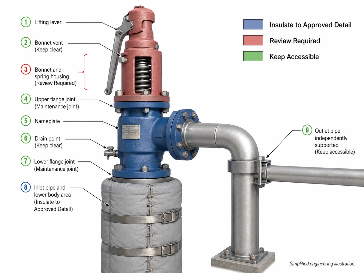
Conceptual component map. Final coverage depends on the selected valve design, manufacturer instructions and installation.
| Valve area | Possible treatment | Main risk | Required confirmation |
|---|---|---|---|
| Inlet piping | Usually follows the approved piping insulation design | Additional heat conduction into the valve | Piping specification and inlet arrangement |
| Valve body | May be insulated for process or personnel-protection reasons | Higher trim or bonnet temperature; hidden leakage | Valve design and manufacturer guidance |
| Bonnet and spring housing | Configuration-dependent | Reduced cooling, hidden vent or obstructed maintenance | Bonnet design and component limits |
| Lifting lever | Keep operable and accessible where fitted | Loss of inspection or functional access | Valve, service and project requirements |
| Bonnet vent | Keep functional where required | Incorrect bonnet-space pressure or concealed discharge | Conventional, bellows or pilot configuration |
| Body or discharge drain | Keep open and serviceable | Condensate or liquid accumulation | Drainage and discharge design |
| Nameplate and adjustment seals | Keep readable and inspectable | Loss of identification and traceability | Owner and QA requirements |
| Flange joints and bolting | Maintain planned access | Difficult removal or leakage inspection | Maintenance strategy |
Construction boundary: “Insulate the valve” is not a complete installation instruction. The approved drawing should identify where insulation stops, which sections are removable, and which openings and joints remain accessible.
How Bonnet and Spring Configuration Changes the Decision
Open Bonnet Safety Valves
An open bonnet exposes the spring assembly to surrounding air and may be selected where atmospheric cooling or visual access is part of the design. Covering the open area can change the intended cooling path and may obstruct the lever or spring inspection. Review the separate open bonnet safety valve page for the product-family boundary.
A model-specific example supports this boundary: Emerson’s Crosby EM-Series literature states that its EMH open-bonnet design allows atmospheric air to provide partial spring cooling for higher process temperatures and also warns that some process fluid may escape through the open bonnet during relief. Emerson Crosby EM-Series data sheet, not a universal rule for all open-bonnet safety valves.
Open bonnet does not automatically mean that the valve is suitable for every hot service. Medium hazards, phase, set pressure, relieving temperature, discharge behavior and project requirements still govern selection.
Closed and Radiator Bonnet Designs
A closed bonnet protects the spring chamber from the external environment, but the word “closed” does not authorize unrestricted insulation coverage. Heat can still conduct into the spring, adjusting assembly and guides. Extended or radiator-style bonnet geometry may be intended to manage heat transfer and should remain unobstructed unless the manufacturer provides a specific insulation detail.
Manufacturer instructions can set a more explicit boundary. LESER’s 2025 operating instructions state that, for applications requiring insulation, the bonnet and any cooling zone are normally left uninsulated to avoid unacceptable heat build-up around the spring. LESER 2025 operating instructions.
Bellows Vents and Pilot Components
Balanced-bellows and pilot-operated designs introduce additional parts that may require open venting, temperature control or maintenance access. Insulation must not conceal a bellows vent, pilot, sensing line, filter, tubing joint, drain or purge point. A valve-type name alone does not establish the permitted boundary.
Preliminary Configuration Screening Matrix
| Configuration or service | Primary insulation concern | Preliminary direction | Confirmation needed |
|---|---|---|---|
| Open bonnet in continuous hot service | Loss of atmospheric cooling and obstructed spring or lever access | Keep the open bonnet region clear unless a model-specific detail states otherwise | Manufacturer installation and temperature data |
| Closed or radiator bonnet | Heat soak into the upper assembly or obstruction of intentional cooling geometry | Do not assume “closed” permits full wrapping | Bonnet design and component-temperature limits |
| Balanced bellows | Covered bonnet vent or unreviewed bellows temperature | Keep the required vent functional and visible | Vent arrangement, bellows material and back-pressure basis |
| Pilot-operated valve | Concealed pilot, sensing line, filter, dome or tubing joints | Provide removable access and temperature control for the pilot system | Model-specific pilot and sensing-line instructions |
| Viscous or solidifying medium | Insulation may retain heat but fail to maintain a clear internal flow path | Review heat tracing or a purpose-designed jacketed configuration | Medium behavior, shutdown condition and heating-system design |
| Replacement valve in an existing insulated line | Old jacket no longer matches the new bonnet, drain, lever or flange layout | Do not reuse the old insulation detail by appearance alone | New GA, nameplate, capacity basis and management-of-change review |
Can Insulation Affect Set Pressure, Stability or Seat Leakage?
Insulation can change component temperature, but it should not be treated as a proven cause of every set-pressure, leakage or stability problem. Spring behavior, internal clearances, gasket compression, soft-seat limits, bellows properties and pilot components may be temperature-sensitive, yet the significance depends on the actual model and thermal exposure.
The National Board’s temperature guidance explains that service and ambient temperature can affect valve operation, cold differential test pressure and capacity, and that manufacturer literature should be consulted when applying correction factors. National Board temperature guidance, but it does not prove that a particular insulation change has altered the installed valve.
Set Pressure Is Not Capacity
A valve may open at the expected set pressure and still be inadequate for the governing required relieving load. Connection size also does not prove capacity. Relief sizing and documented capacity remain separate from the insulation review. Use the confirmed guide to safety valve sizing and certified relieving capacity when reviewing the protection basis.
Seat, Seal and Gasket Limits
Review the complete temperature-sensitive assembly, including the nozzle, disc, guide, spindle, spring, bellows, soft-seat insert, O-ring, gasket, packing and pilot seals where fitted. Body material alone does not prove that the complete valve is suitable. Pressure-temperature capability must be checked against material group, pressure class or PN, component design and the selected valve’s published limits; the related pressure-temperature ratings guide provides the broader standards context.
Why Insulation Alone Does Not Diagnose Chatter
Chatter or unstable opening may involve excessive inlet pressure loss, an oversized selected orifice, built-up back pressure, variable superimposed back pressure, insufficient sustainable flow, unsuitable valve configuration, piping load or damaged internals. Insulation may be one contributor to a temperature-related condition, but it does not replace the full installed-system review. For dedicated context on conventional and balanced configurations, continue with the back pressure and bellows review.
Insulation vs Heat Tracing vs Jacketed Safety Valves
External insulation, heat tracing and a jacketed valve solve different thermal problems. They must not be treated as interchangeable solutions.
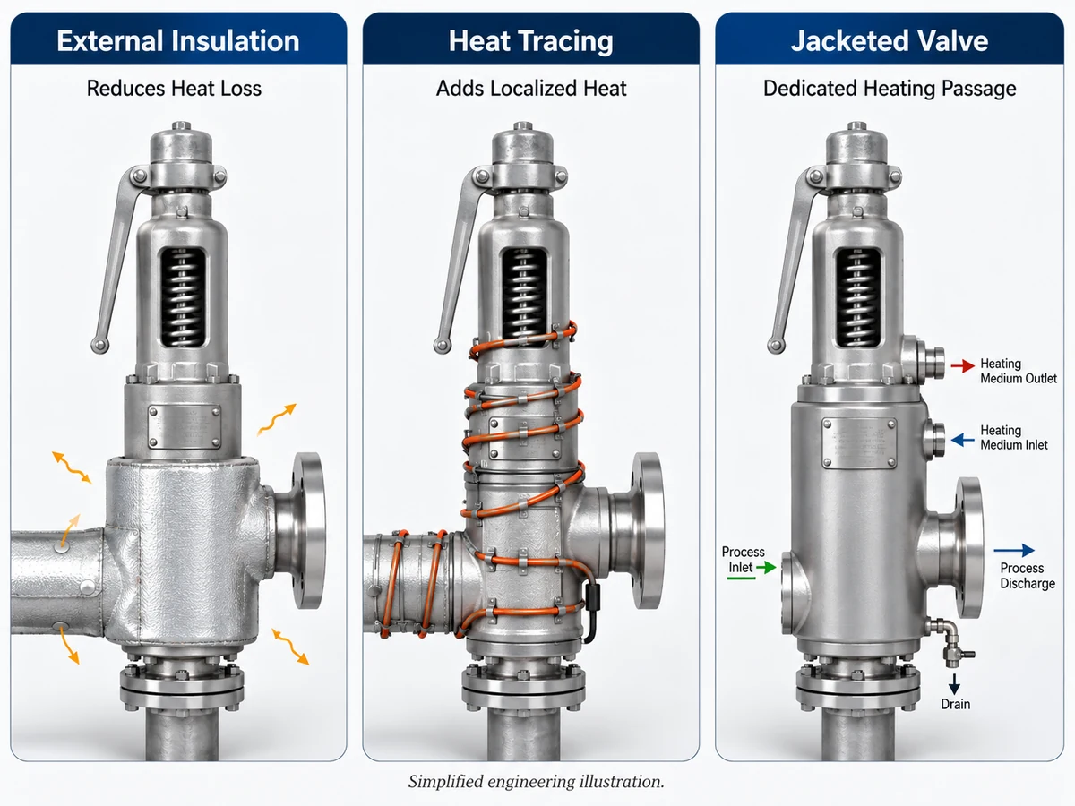
Simplified engineering comparison. The bonnet, spring housing, lever, vent, drain, nameplate and maintenance joints remain untraced and accessible.
External Insulation
Reduces heat loss to the surroundings. It does not actively guarantee a controlled internal temperature and should not cover functional parts without approval.
Heat Tracing
Adds electrical or fluid heat to selected surfaces. Review control temperature, fault temperature, local hot spots, termination and maintenance access.
Jacketed Valve
Uses a dedicated heating or cooling passage around selected valve-body areas. It requires a separate valve configuration and process-medium review.
For viscous, crystallizing or solidifying media, insulation alone may not maintain the required flow-path condition. A purpose-designed jacketed safety valve may require review, but a heating jacket still does not correct an inadequate required capacity, wrong relief scenario or unsuitable material selection.
Installation and Maintenance Risks Created by Poor Insulation
Access and Operability
- Covered lifting lever or adjustment cap
- Hidden nameplate and repair identification
- Inaccessible flange bolts and removal joints
- Concealed pilot tubing or sensing connections
Drainage and Moisture
- Blocked bonnet, body or discharge drain
- Water directed into a bonnet joint
- Wet insulation retained around bolting
- Poorly resealed removable jacket after maintenance
Mechanical Load
- Rigid cladding bridging a joint
- Insulation support loading the valve body
- Unreviewed thermal movement
- Heavy outlet piping supported by the valve
Inspection and Reinstatement
- Leakage hidden by permanent coverage
- Jacket reinstalled in the wrong orientation
- Vent or drain opening omitted after maintenance
- No as-built insulation-boundary record
Moisture and Maintenance Control Matrix
| Observed condition | Potential consequence | Check before return to service |
|---|---|---|
| Damaged cladding seam or open jacket penetration | Water entry and hidden corrosion around the body, bolting or drain connection | Dry condition, coating condition, weather seal and inspection record |
| Drain terminates inside insulation | Retained condensate, corrosion or concealed leakage | Open drain path, visible termination and safe routing |
| Permanent insulation bridges a removable flange | Delayed maintenance, damaged insulation and uncontrolled reinstallation | Removable section, joint clearance and reinstatement method |
| Jacket reinstalled in a different orientation | Covered vent, lever, nameplate or inspection point | Approved orientation, access openings and closeout photograph |
| Insulation or cladding bears on the valve or outlet | Unintended mechanical load, misalignment or restricted thermal movement | Independent support, movement clearance and load-free valve connections |
Hold Points: When Insulation Work Should Not Proceed
Stop construction or reinstatement when a missing input could affect pressure protection, component temperature, venting, drainage or traceability.
| Unresolved condition | Why it matters | Required action |
|---|---|---|
| Valve model, nameplate or GA is unavailable | The bonnet, vent, lever, drain and removal joints cannot be confirmed reliably. | Identify the valve and obtain manufacturer documentation. |
| Operating or relieving temperature is unknown | Spring, bellows, seat, gasket and tracing exposure cannot be checked. | Confirm normal, relieving, start-up, shutdown and cleaning temperatures where applicable. |
| Required capacity or relief scenario has changed | The existing valve may no longer protect the governing case, regardless of insulation quality. | Revalidate sizing and documented capacity through management of change. |
| Bonnet vent, drain or lever would be covered | Function, inspection and safe discharge may be compromised. | Revise the boundary or obtain an approved removable detail. |
| Heat-tracing maximum or fault temperature is undefined | Local component limits may be exceeded even when the normal set point appears acceptable. | Define control, alarm and fault-case temperatures. |
| Moisture barrier or post-maintenance reinstatement is not defined | CUI, hidden leakage and incorrect jacket orientation can develop. | Complete the insulation specification and maintenance closeout procedure. |
Engineering Review Workflow Before Insulating the Valve
Define the Service and Relief Case
Record the protected equipment, governing relief scenario, medium and phase, operating pressure, MAWP or design pressure, set pressure, required relieving capacity, operating temperature and relieving temperature.
Identify Temperature-Sensitive Components
Confirm body, nozzle, disc, guide, spindle, spring, bonnet, bellows, seat, seal, gasket, packing and pilot components. Product-family ranges must not be applied automatically to an unconfirmed model.
Mark the Insulation Boundary
Use the general arrangement drawing to show insulated areas, removable sections, vents, drains, lever clearance, tracing termination, nameplate visibility and maintenance joints.
Verify Documentation and Access
Confirm manufacturer instructions, project specification, adopted code edition, insulation system, CUI controls, maintenance-removal method, inspection points and as-built record requirements.
Composite Engineering Scenarios
The following are composite engineering scenarios for training. They do not describe a specific customer, plant, incident or tested ZOBAI installation.
Spring Housing Fully Wrapped
Observed condition: Piping insulation continued over the body and complete spring housing.
Concern: The arrangement changed the heat-dissipation path and concealed identification and access.
Control: Remove unapproved coverage and issue a valve-specific insulation drawing.
Heat Tracing Used as a Substitute
Observed condition: Tracing was added around a conventional valve serving a medium that could become highly viscous.
Concern: Uneven heating did not prove that the relief flow path would remain clear.
Control: Reassess the medium and whether a dedicated jacketed configuration is required.
Removable Jacket Reinstalled Incorrectly
Observed condition: After maintenance, the jacket covered a drain and part of the nameplate.
Concern: Drainage, moisture control and traceability were reduced.
Control: Reinstate the jacket against an approved orientation drawing and closeout checklist.
Safety Valve Insulation Inspection Checklist
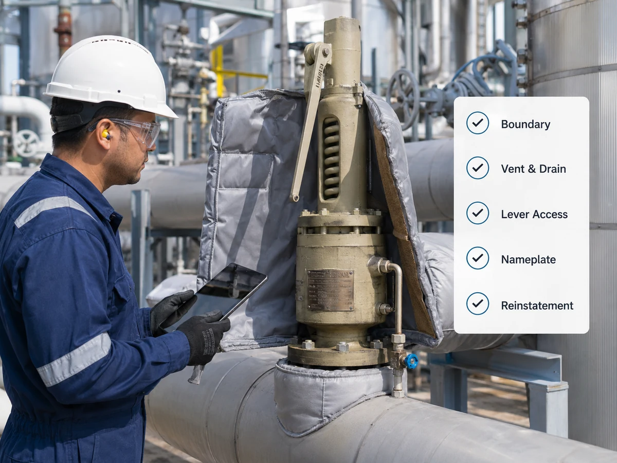
Illustrative inspection scene. Site procedures and PPE depend on the facility and service condition.
Installation Checks
- Valve model and service match approved documents
- Insulation boundary matches a marked drawing
- Bonnet and spring treatment is model-specific
- Vents and drains remain functional
- Lifting lever remains accessible where fitted
- Nameplate and seals remain inspectable
- Flange and removal access is retained
System and Maintenance Checks
- Outlet piping is independently supported
- Cladding does not impose valve load
- Heat tracing remains within approved limits
- Weather sealing and CUI controls are complete
- Leakage inspection points remain visible
- Post-maintenance reinstatement procedure exists
- Manufacturer and project requirements are recorded
What to Send for an Insulation or High-Temperature Valve Review
Service and Pressure Data
- Protected equipment and governing relief scenario
- Medium, composition and phase
- Operating pressure and MAWP or design pressure
- Set pressure
- Required relieving capacity and calculation basis
- Operating and relieving temperatures
- Superimposed and built-up back pressure
Valve, Piping and Insulation Data
- Valve manufacturer, model, datasheet and nameplate photo
- Bonnet, spring, bellows, seat and seal configuration
- General arrangement and inlet/outlet piping drawing
- Proposed insulation material, thickness and coverage
- Heat-tracing or jacket details
- Applicable code, project specification and required documents
Review Output and Document Matrix
| Document or record | What it should confirm | What it does not prove by itself |
|---|---|---|
| Valve datasheet and GA | Configuration, connections, materials, vents, drains and access points | That the valve capacity is adequate for a changed relief scenario |
| Relief calculation and capacity basis | Required load, selected orifice and documented relieving capacity | That the installed insulation boundary is acceptable |
| Set-pressure or calibration report | Test condition and as-left set-pressure result | Installed capacity, seat tightness or piping stability |
| Seat-tightness report | Leakage result under the stated test method and condition | Relieving capacity or high-temperature field tightness |
| Insulation and tracing drawing | Coverage, removable sections, access, penetrations and tracing termination | Valve certification or suitability for every process condition |
| Maintenance reinstatement record | Vents, drains, lever, nameplate, weather seal and jacket orientation restored | That a changed process or relief case has been re-sized |
Late discovery that a standard valve requires a different bonnet, high-temperature trim, bellows material, jacketed body or custom removable insulation can affect drawings, testing scope, procurement cost and lead time. Confirm these requirements before quotation and fabrication release.
Final selection and insulation approval require manufacturer data, project review, the adopted code edition and applicable local regulatory requirements. For the broader product scope, review high-temperature safety valves.
Technical References
Current official publisher pages list API 520 Part I as the 10th Edition, API 520 Part II as the 7th Edition, ASME BPVC Section XIII as the 2025 Edition, and ISO 4126-1:2013 as reviewed and confirmed in 2025. The owner and project must still verify the adopted edition, scope and jurisdictional requirements.
- API 520 Part I, 10th Edition—sizing and selection scope
- API 520 Part II, 7th Edition—installation scope
- ASME BPVC Section XIII, 2025 Edition—overpressure-protection reference
- ISO 4126-1:2013—safety-valve product requirements; confirmed in 2025
- National Board—temperature considerations for pressure-relief valve application
- LESER 2025 operating instructions—manufacturer-specific insulation and cooling-zone guidance
- AMPP—corrosion under insulation overview
Frequently Asked Questions
Should a high-temperature safety valve body be insulated?
It may be insulated when the process and installation design require it, but the effect on body, trim, bonnet and spring temperatures must be reviewed. Body insulation does not automatically authorize bonnet or spring-housing coverage.
Can the bonnet or spring housing be covered with insulation?
There is no universal answer. Open bonnets, closed bonnets, radiator bonnets and bellows designs have different cooling, venting and maintenance requirements. Confirm the selected model’s instructions before covering the bonnet.
Can insulation change a safety valve’s set pressure?
Insulation can change component temperature, which may affect spring behavior or clearances. That does not prove the set pressure has changed. Manufacturer review and appropriate testing are required before reaching that conclusion.
Should the lifting lever remain outside the insulation?
Where a lifting lever is fitted and required to remain functional, it should be accessible and unobstructed. The exact lever requirement depends on the valve, service, governing code and project specification.
What is the difference between insulation and a jacketed safety valve?
Insulation reduces heat loss. A jacketed valve intentionally circulates a heating or cooling medium around selected body areas. A jacket is a valve configuration, not an external insulation blanket.
Can insulation cause corrosion around a safety valve?
Moisture entering or remaining beneath insulation can create corrosion-under-insulation risk. The actual risk depends on material, temperature cycling, coating, insulation system, weather sealing and inspection controls.
What information is needed before approving the insulation boundary?
Provide the valve datasheet and GA, medium, operating and relieving temperatures, bonnet and spring design, pressure and capacity data, piping arrangement, proposed insulation detail, heat-tracing information and manufacturer requirements.
Does insulation change a safety valve’s relieving capacity?
Insulation does not establish or recalculate relieving capacity. It may change component temperature and therefore require a model-specific temperature review, but required capacity and documented valve capacity must still be verified from the governing relief case, fluid basis, relieving conditions and manufacturer data.
Standards and Liability Note
Current official publisher pages list API 520 Part I as the 10th Edition, API 520 Part II as the 7th Edition, ASME BPVC Section XIII as the 2025 Edition, and ISO 4126-1:2013 as confirmed in 2025. These references define different scopes and do not complete a valve specification or prove that a specific ZOBAI model carries a particular certification. Verify the project-adopted edition, protected-equipment code, relief scenario, required capacity, valve configuration, installation requirements and local regulatory obligations.
Connection size is not relieving capacity. Set pressure is not required or certified capacity. Steam, gas, liquid and two-phase capacity bases are not directly interchangeable. Final engineering confirmation depends on real operating conditions, manufacturer data and project review.
Request an Insulation Boundary Review
Send the protected equipment, relief scenario, medium and phase, operating pressure, MAWP or design pressure, set pressure, required relieving capacity, operating and relieving temperatures, back-pressure conditions, valve datasheet, nameplate, bonnet configuration, piping drawing and proposed insulation detail.