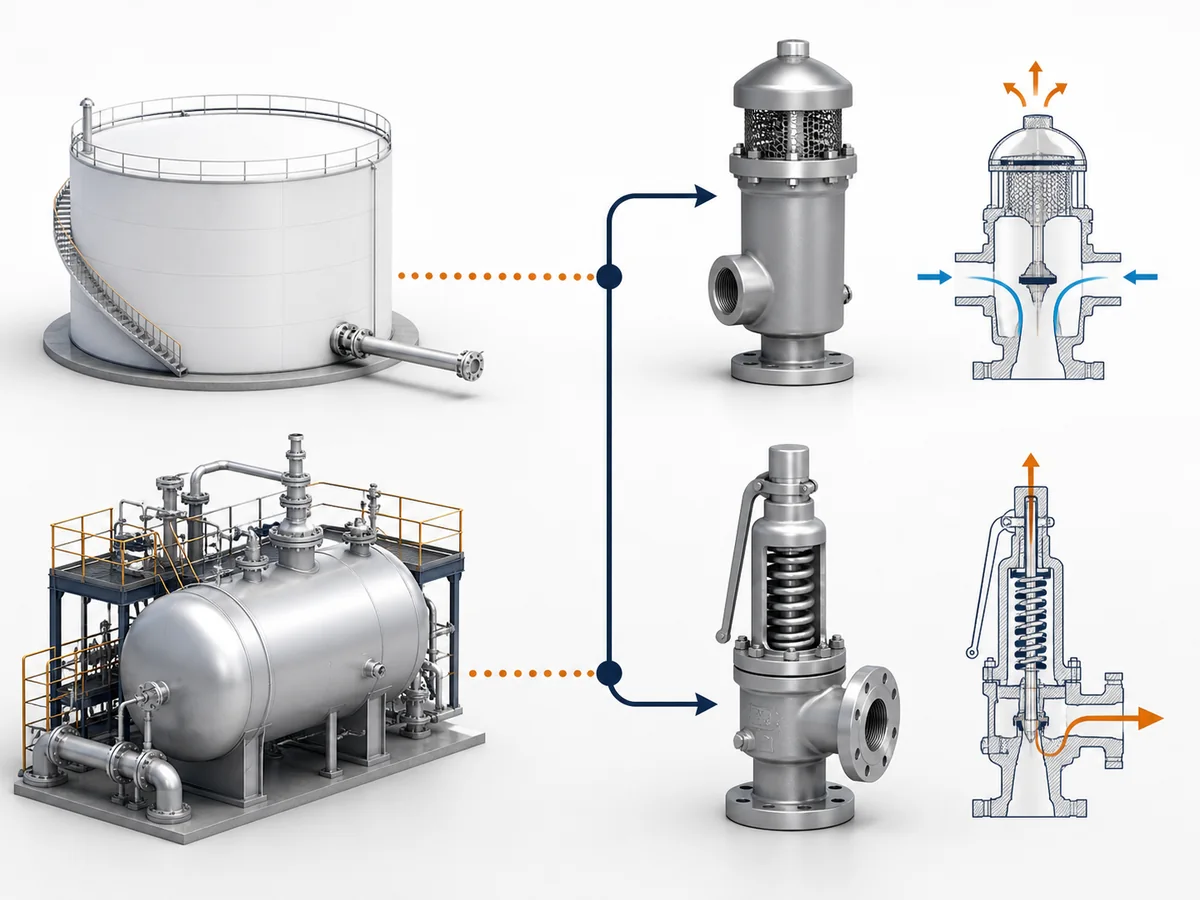
A pressure-vacuum relief valve (PVRV) and a safety valve can both respond to pressure conditions, but they solve different protection problems. In this article, a PVRV means a device used as part of the pressure-and-vacuum protection of an atmospheric or low-pressure storage tank. A safety valve means an overpressure protection device applied to pressurized equipment …

A pressure-vacuum relief valve (PVRV) and a safety valve can both respond to pressure conditions, but they solve different protection problems. In this article, a PVRV means a device used as part of the pressure-and-vacuum protection of an atmospheric or low-pressure storage tank. A safety valve means an overpressure protection device applied to pressurized equipment under the applicable design and protection basis.
The practical distinction is not simply valve construction. It is the combination of protected equipment, required duty, governing scenario and sizing basis.
A tank PVRV review can require outward pressure-side venting and inward vacuum-side flow, while normal and emergency tank venting remain separate checks. A safety-valve review instead starts from an applicable overpressure relieving case, establishes the required relieving capacity, and then verifies suitable device capacity and the supporting capacity evidence required by the governing basis.
Because those engineering paths begin with different questions, a matching connection, similar pressure designation or physical fit is not enough to show that one device can replace the other.
Start With the Protected Equipment and Relief Duty
Before comparing valve sizes, settings or connections, identify what equipment is being protected and what pressure boundary must be protected. The equipment name alone is not enough: the actual design basis and required protection duty determine which engineering path applies.
Atmospheric or Low-Pressure Tank Protection
For an atmospheric or low-pressure storage tank, the protection question can involve pressure in both directions.
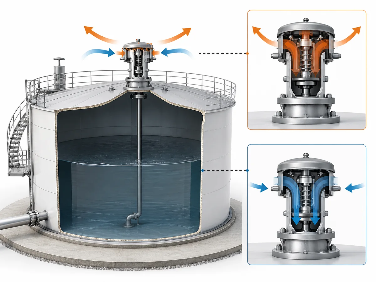
Positive pressure can require vapor or gas to leave the tank. Excessive vacuum can require gas to enter the tank so that the internal pressure does not fall beyond the tank’s permitted vacuum condition. A PVRV can therefore combine a pressure-relief function with a vacuum-relief function.
Tank-venting frameworks such as API 2000 and ISO 28300 address both overpressure and vacuum conditions for the covered storage-tank applications. Within this article’s scope, that makes tank protection a pressure-and-vacuum problem rather than a positive-pressure-only problem.
The PVRV is therefore not selected merely because a tank has a nozzle of a particular size. The required protection depends on the tank design basis and on the scenarios that create pressure-side and vacuum-side venting demand.
Pressurized-Equipment Overpressure Protection
For the safety-valve side of this comparison, the core problem is different: applicable pressurized equipment requires protection against an overpressure condition.
The engineering review first determines the applicable overpressure scenario that creates the relief demand. That demand establishes the required relieving capacity that the selected pressure-relief device must be able to satisfy.
ASME overpressure-protection rules and API pressure-relief guidance treat this as a pressure-relief-device problem for covered pressurized equipment. That is a different engineering basis from determining how an atmospheric or low-pressure tank must breathe during operation.
A safety valve selected for positive-pressure overpressure protection cannot be taken as evidence that a separate vacuum or inbreathing requirement has also been satisfied merely because it is installed on the same equipment or has a similar connection.
The first procurement decision is therefore: Is the unresolved requirement tank pressure-and-vacuum venting, or pressurized-equipment overpressure relief?
That classification should be settled before comparing replacement dimensions, pressure markings or catalog families.
How PVRV Duty Is Built From Pressure, Vacuum, Inbreathing and Outbreathing
PVRV duty cannot be represented adequately by one positive-pressure requirement. For the tank applications in scope here, the review must distinguish the pressure side from the vacuum side and establish the required venting demand in each direction.
Outbreathing on the Pressure Side
Outbreathing means gas or vapor must leave the tank when conditions increase internal pressure.
Tank filling or other operating conditions can create outward venting demand. The engineering task is to determine the required pressure-side venting capacity under the applicable tank-venting basis and confirm that the proposed device can provide that capacity at the relevant conditions.
This is a tank-system capacity question. Connection diameter alone tells neither the required venting capacity nor the device’s available venting capacity.
Inbreathing on the Vacuum Side
Inbreathing is the inward-flow requirement when conditions tend to reduce tank pressure below the acceptable vacuum condition.
Tank emptying or pump-out can create an inward gas requirement, and thermal effects may also need to be considered under the applicable tank-venting basis.
A combined PVRV therefore has two different functional directions:
- the pressure side allows outward flow when positive-pressure protection is required;
- the vacuum side allows inward flow when vacuum protection is required.
Pressure-side adequacy alone says nothing about vacuum-side adequacy. A positive-pressure relief device selected only for an overpressure case likewise does not automatically provide the required inward-flow function.
Why Dual-Direction Duty Cannot Be Reduced to One Pressure Figure
A common specification error is to reduce an existing PVRV to its connection size and one pressure setting. That can omit the entire vacuum side of the protection requirement.
A proper tank-side review may need separate information for:
- tank design pressure;
- tank design vacuum;
- pressure-side setting;
- vacuum-side setting;
- required outbreathing capacity;
- required inbreathing capacity;
- the operating scenarios that create those requirements.
The exact project inputs depend on the governing tank design and venting basis, but the decision rule is stable: a two-direction protection duty should not be approved from a one-direction specification.
Normal Venting, Emergency Venting and Blanketing Are Separate Tank-System Checks
A PVRV does not remove the need to identify the scenarios for which the tank protection system must be evaluated. In particular, normal venting and emergency venting are separate requirements.
Normal Venting Versus Emergency Venting
Normal venting addresses pressure and vacuum changes associated with the operating and thermal conditions covered by the applicable tank-venting basis.
Emergency venting addresses a separate emergency requirement.
API 2000 and ISO 28300 distinguish normal and emergency venting within their tank-venting scope. The procurement consequence is direct: adequate normal pressure-side and vacuum-side venting capacity is not proof that the emergency venting requirement has also been satisfied.
Conversely, identifying an emergency venting path does not remove the need to establish the normal pressure-side and vacuum-side breathing duties that apply during operation.
This distinction does not prescribe one universal number or arrangement of physical devices. The required protection arrangement depends on the applicable tank design, project requirements and selected equipment.
The correct engineering question is therefore not simply whether a PVRV is present. It is which normal and emergency venting duties the complete protection arrangement must satisfy, and which device or combination of devices is responsible for each duty.
Detailed emergency-vent sizing remains outside this comparison.
Where Blanketing Enters the Tank-Side Review
A tank may also operate with a blanketing system. When it is present, the blanketing system becomes part of the tank’s gas-balance and protection review.
The frozen application evidence for this article treats blanketing information alongside tank filling, emptying, pressure, vacuum and breathing requirements. That supports treating blanketing as a relevant tank-side engineering input rather than as an unrelated accessory.
However, a blanketing regulator and a PVRV perform different functions.
Neither function can stand in for the other: blanketing does not remove the need for the required pressure-vacuum protection, while the presence of a PVRV does not prove that every blanketing-related or emergency condition has been addressed.
For procurement purposes, the useful rule is: if blanketing is present, disclose it as part of the tank-side engineering input rather than reviewing the vent valve in isolation.
Detailed blanketing-system design belongs to the tank-system engineering path, not to this comparison article.
How Safety-Valve Sizing Starts From the Governing Overpressure Case
Safety-valve sizing follows a different logic because the engineering question is not how a tank must breathe. It is what applicable overpressure scenario the protected pressurized equipment must be relieved against.
API pressure-relief guidance and ASME overpressure-protection requirements place the safety-valve problem in a separate relief-device framework from atmospheric or low-pressure tank venting.
Establish the Governing Relieving Case Before Valve Size
A safety valve should not be sized by starting with a desired connection diameter.
The protected system must first be evaluated for the applicable overpressure scenarios. The scenario that establishes the controlling relief demand provides the basis for the required relieving capacity.
This sequence matters because a valve can physically fit the available connection without having the capacity required by the applicable relieving case.
The engineering path is conceptually: overpressure scenario → required relieving capacity → device capacity verification.
This article deliberately stops at that decision boundary. Calculating the relieving load, selecting an orifice and applying detailed sizing methods belong to the dedicated safety-valve sizing process.
Required Relieving Capacity Is Not the Same as Connection Size
Required relieving capacity is a system-side requirement. Connection size is a physical interface.
They are therefore not interchangeable engineering quantities.
Inlet and outlet connections matter to installation and can affect the final valve configuration, but connection size alone is not evidence that a particular safety valve can satisfy the relieving demand.
A replacement review should preserve the actual sizing basis or establish a new valid basis rather than treating nominal size as evidence of relief capacity.
Capacity Certification or Supporting Documentation Where Applicable
The safety-valve side also requires a distinction between the capacity the protected system requires and the capacity evidence available for the selected valve.
Where capacity certification is required by the governing basis, certified relieving capacity or corresponding supporting documentation can provide device-side evidence. Where a different documentation basis applies, the project should use the evidence required for that case.
Certification terminology therefore cannot be treated as universal.
A generic catalog flow value should not automatically be described as certified relieving capacity, and a PVRV vent-capacity rating should not simply be renamed as safety-valve certified relieving capacity unless the governing basis actually supports that terminology.
The procurement decision is consequently two-part: first establish the required system capacity; then verify that the proposed device has the appropriate supporting capacity evidence.
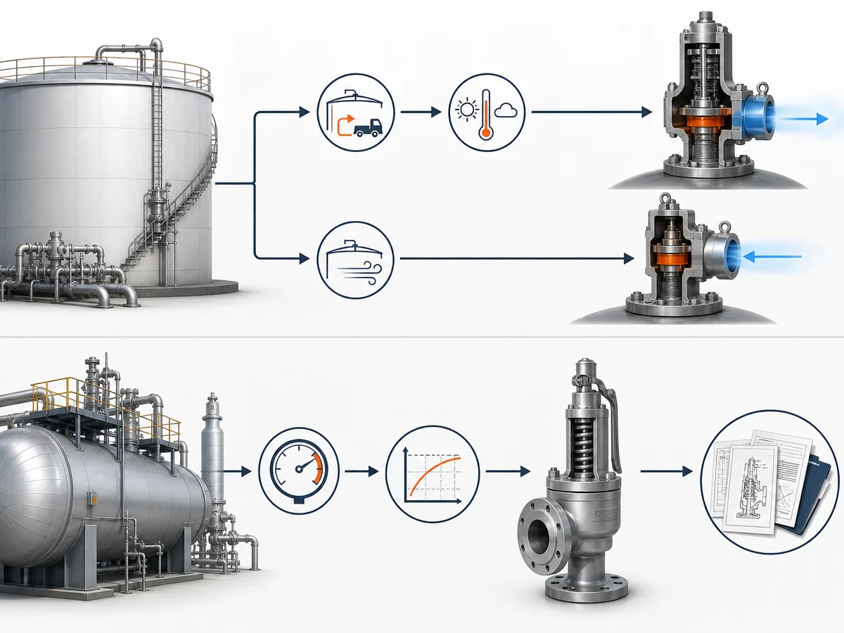
Why PVRV and Safety-Valve Sizing Bases Are Not Interchangeable
The strongest reason not to substitute these devices from a catalog comparison is that they answer different engineering questions.
A PVRV review begins with the pressure and vacuum limits of a tank and the conditions that create outward and inward venting demand. A safety-valve review begins with the applicable overpressure scenario and the required relieving capacity of pressurized equipment.
Those paths can both end with a valve and a capacity check, but their upstream sizing bases are different.
Different Inputs Produce Different Capacity Checks
| Decision area | PVRV / tank-venting route | Safety-valve / overpressure route |
|---|---|---|
| Protected equipment | Atmospheric or low-pressure tank within the article scope | Applicable pressurized equipment |
| Primary duty | Pressure-side outbreathing and vacuum-side inbreathing | Protection against an applicable overpressure relieving case |
| Sizing basis | Tank pressure-vacuum limits and scenarios creating outward and inward venting demand | Applicable overpressure scenario and required relieving capacity |
| Capacity verification | Pressure-side and vacuum-side venting requirements, with emergency venting separately checked as applicable | Required relieving capacity compared with suitable device capacity evidence under the governing basis |
On the tank/PVRV side, relevant information can include:
- tank design pressure and vacuum;
- pressure and vacuum settings;
- filling and emptying basis;
- normal outbreathing and inbreathing requirements;
- thermal venting considerations where applicable;
- blanketing information where present;
- separate emergency venting requirements.
On the safety-valve side, relevant information can include:
- protected pressurized equipment;
- applicable overpressure scenario;
- required relieving capacity;
- set-pressure requirement;
- relieving conditions;
- fluid phase and required properties;
- back pressure and discharge-system conditions;
- valve capacity evidence and documentation required by the governing basis.
Because the input sets are different, a device selected through one path should not be treated as suitable for the other merely because both devices have a pressure-related function.
Mechanical Fit or a Similar Setting Does Not Establish Equivalence
Superficial similarities can be useful for identifying a candidate replacement, but they are not sufficient for approving protection equivalence.
- Connection match: the replacement appears to fit the same inlet, outlet or flange arrangement.
- Setting match: a pressure designation appears similar to the existing device.
- Physical similarity: the device appears capable of mounting in the same location.
Those observations may address mechanical compatibility, but they do not establish protection equivalence.
Before approving substitution, the review should answer these engineering questions:
- Is the replacement being evaluated for the same protected equipment and the same design basis?
- Does it preserve the required function: pressure-and-vacuum tank protection or pressurized-equipment overpressure relief?
- Are the governing operating, emergency or overpressure scenarios still represented in the sizing basis?
- Does the proposed device have suitable capacity evidence and installed-condition information for the relevant protection path?
If any of those questions remains unresolved, matching dimensions or one similar pressure value should not be used to close the equivalence decision.
Replacement Must Preserve the Actual Protection Duty
A sound replacement review should reconstruct the original protection requirement before approving the substitute.
If the existing device protects a tank against both excessive pressure and excessive vacuum, the replacement review should retain both functions and the relevant pressure-side and vacuum-side capacity requirements.
If the existing device protects pressurized equipment against an applicable overpressure case, the replacement should be checked against that relieving requirement rather than only against the old valve’s nominal connection.
If the original engineering inputs are unavailable, treat them as unresolved project data rather than inferring them from appearance, catalog dimensions or a single pressure designation.
The central substitution rule is: matching hardware does not establish matching duty, and matching one pressure value does not establish matching sizing basis.
What to Send in an RFQ for Each Protection Route
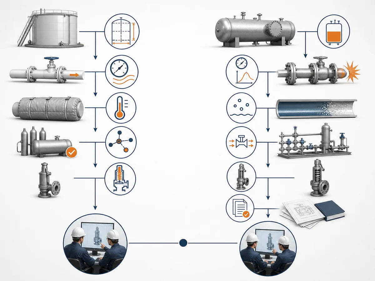
A useful RFQ should make the protection problem visible to the supplier or engineering reviewer. Valve size, pressure and material alone are often not enough to distinguish a tank PVRV requirement from a pressurized-equipment safety-valve requirement.
The required project data can vary, but the following two branches provide a practical starting point. Missing governing data should be marked as unresolved rather than filled from an unrelated catalog value.
PVRV / Tank-Venting Input Branch
For an atmospheric or low-pressure tank pressure-vacuum enquiry, provide the applicable information available for the project:
- protected tank type and design basis;
- tank design pressure;
- tank design vacuum;
- required pressure-side setting;
- required vacuum-side setting;
- filling or inflow basis;
- emptying or pump-out basis;
- thermal venting basis where relevant;
- blanketing-system information where present;
- required pressure-side venting capacity;
- required vacuum-side venting capacity;
- emergency venting basis;
- vent or discharge arrangement and relevant restrictions;
- process medium or vapor and material-compatibility requirements;
- existing valve data sheet or identification information for replacement work.
The purpose of this branch is not to perform PVRV sizing inside the RFQ. It is to make sure the enquiry shows that pressure-side, vacuum-side and emergency requirements are separate questions that may each need verification.
Safety-Valve / Overpressure Input Branch
For a safety-valve enquiry on applicable pressurized equipment, provide the applicable project information available for the relief review:
- protected equipment;
- applicable overpressure scenario;
- applicable equipment or project design basis;
- operating pressure;
- required set pressure;
- required relieving capacity;
- relieving pressure and temperature conditions;
- fluid phase and required fluid-property information;
- candidate orifice or available capacity information, if already established;
- back pressure and discharge-system conditions;
- required capacity certification or supporting documentation where applicable;
- existing valve nameplate, data sheet or sizing calculation for replacement work.
This branch is built around the overpressure relieving requirement and the evidence needed to verify the proposed device against it, not around tank inbreathing and outbreathing.
When to Route the Question to a Dedicated Technical Owner
This comparison should stop once the correct protection path is identified.
A tank question that requires detailed normal venting, emergency venting or blanketing analysis belongs in the tank-venting engineering path.
A safety-valve question that requires relieving-load calculation, orifice selection or detailed capacity verification belongs in the dedicated safety-valve sizing path.
A general safety-valve construction or selection question belongs in the safety-valve selection topic.