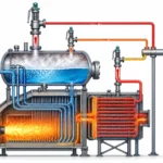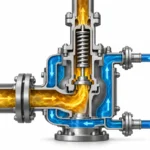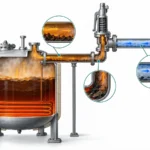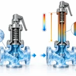
Learn how to review refrigeration relief valve discharge piping, common headers, back pressure, simultaneous relief cases, and engineering RFQ inputs.

Refrigeration relief valve discharge piping is part of the relief system, not simply a connection added after the valve has been sized. A valve can have an adequate relieving-capacity basis and still be installed in an outlet system that creates excessive back pressure, combines flow from other relief devices, or imposes a downstream condition that the selected valve has not been verified to tolerate.
For a single discharge line, the review starts with the required relief duty, the actual valve, the downstream boundary condition, and the installed piping path. For a common relief header, another question comes first: which relief sources can credibly discharge together in the scenario being evaluated?
The engineering sequence is relief duty → valve capability → individual branch → common-header scenario → downstream pressure → valve-specific verification → final discharge and installation checks.
A common mistake is to start with the header diameter. The more defensible starting point is the relief scenario and downstream design basis, then the piping network, and only then the acceptance of each connected relief device.
Why Discharge Piping and Header Design Is a Separate Relief-System Check
Three engineering questions have to remain separate.
Relief duty asks: how much flow must leave the protected equipment?
Valve capacity asks: can the selected pressure-relief device pass that duty under its applicable rating or certified-capacity basis?
Discharge-system review asks: what downstream pressure and physical conditions will the installed outlet piping impose while the valve is relieving?
ISO 24664:2024 treats required mass flow, relief-device discharge capacity, and pressure loss in associated inlet and outlet lines as distinct calculation subjects within one refrigeration pressure-relief framework. That is the core reason a correct valve-capacity check does not close the piping review.
Connection size is not relieving capacity
The valve outlet connection is a mechanical interface. It is not the same thing as the flow area, certified relieving capacity, or installed discharge-system capacity. A replacement valve can fit the same flange or threaded connection yet have a different certified flow basis or a different sensitivity to back pressure. For the upstream sizing question, ZOBAI’s safety valve sizing and certified relieving capacity guide covers that separate task. This article starts from the point where the relief basis is already defined.
Terminology in this article
Pressure-relief device (PRD) is used as an umbrella term when discussing standards and system design. Safety relief valve is used where refrigeration manufacturers or source documents use that product term. The name alone should not be used to infer fluid service, operating characteristic, or certified capacity; those have to come from the applicable code basis and the exact valve documentation.
Illustrative engineering scenario: a vessel relief valve is selected on an adequate capacity basis, then its outlet is routed through a long branch into an existing common vent header. The valve sizing calculation can still be correct while the installed outlet condition is not. The prevention is to treat the branch/header pressure calculation and the valve-specific back-pressure check as separate acceptance steps. This is an illustrative scenario, not a reported ZOBAI project.
Define the Design Basis Before Evaluating the Discharge Piping
A refrigeration relief discharge line or common header cannot be evaluated reliably from pipe diameter alone. Before calculating the downstream path, establish the inputs that control the result.
| Input | Why it matters | If it is unknown |
|---|---|---|
| Refrigerant | Fluid properties and the applicable standards path depend on the service. | Calculation and compliance basis remain open. |
| Relieving phase or state | Vapor, liquid and other relieving states are not interchangeable. | Applicable calculation method remains uncertain. |
| Required relieving flow | Defines the load the downstream system must pass. | Branch and header loading cannot be established. |
| Set and relieving pressure basis | Provides the pressure context for the valve and system. | Downstream pressure cannot be interpreted correctly. |
| Exact relief valve | Valve designs do not all respond identically to downstream pressure. | Final valve acceptance cannot be completed. |
| Valve capacity basis | Establishes the flow basis used in the relief-system review. | Piping calculations may use the wrong flow assumption. |
| Individual branch geometry | Length, fittings, junctions and routing influence pressure loss. | Valve-outlet pressure cannot be calculated reliably. |
| Header topology | Flow changes as branches enter a shared network. | Segment loads remain undefined. |
| Credible coincident relief case | Defines which sources contribute at the same time. | Governing header load remains unresolved. |
| Final destination and terminal pressure | Atmospheric and pressurized or internal discharge are different boundary conditions. | Downstream boundary remains incomplete. |
| Applicable jurisdiction and standard | Requirements differ by refrigerant, jurisdiction and adopted edition. | Final compliance review remains open. |
These inputs fall into three useful groups. Relief-duty inputs describe what must be discharged. Valve inputs describe the device expected to discharge it and the evidence needed to assess that valve. Network inputs describe where the flow goes and what downstream condition the installed piping creates.
The missing input should determine the next action. If relief flow is unknown, the header-load calculation remains unresolved. If actual piping geometry is missing, a defensible pressure-loss result cannot be established. If the exact valve data are unavailable, the network may still be modeled, but the selected valve cannot yet be accepted against that result.
Keep set pressure, overpressure, accumulation, and blowdown separate
These terms describe different parts of pressure-relief behavior and should not be collapsed into one “relief pressure” number. In general PRV terminology, set pressure is the inlet pressure at which the device begins its defined operating action; overpressure is pressure above the valve set pressure; accumulation is the rise of protected-system pressure above its maximum allowable working pressure or applicable allowable pressure basis during discharge; and blowdown is the difference between opening/set pressure and reseating pressure. Baker Hughes’ current safety-valve terminology documents these distinctions; the exact operating definition and permitted limits still depend on the applicable device, code, service, and manufacturer. See the manufacturer’s terminology reference.
Those are primarily upstream or valve-operating terms. Back pressure is a downstream condition. Keeping them separate prevents a common review error: using a correct set-pressure or overpressure basis as though it had already validated the outlet piping.
This is more useful than starting with a nominal outlet size because it identifies exactly what information is still preventing an engineering decision.
How Outlet Piping Creates Back Pressure at the Relief Valve
Back pressure is the pressure acting at the discharge side of the relief valve. The useful design question is where that pressure comes from.
Built-up back pressure develops after the valve opens because relief flow passes through the downstream piping. Superimposed back pressure is already present at the valve outlet before the subject valve opens and may be constant or variable depending on the downstream system. Current Baker Hughes technical guidance uses the same distinction and notes that long runs, bends, and shared downstream systems are typical sources. Backpressure terminology reference.
During a relieving event, the condition seen by the valve can therefore reflect both an existing downstream pressure and additional pressure generated while relief flow moves through the branch and header.
A simplified path is relief valve → branch → header → terminal condition.
The pressure at the valve outlet depends on the downstream boundary plus the resistance between the valve and that boundary. Flow rate, piping dimensions, length, fittings, junctions and the pressure farther downstream can all matter within the applicable calculation method.
That is why the valve’s nominal outlet connection does not prove that the discharge pipe is adequate. The connection defines a physical interface; it does not by itself establish the hydraulic performance of everything connected after it.
For a common header, the distinction becomes more important because another active relief source can alter the shared downstream condition. A deeper valve-side explanation is available in ZOBAI’s back pressure and bellows engineering guide.
For refrigeration systems within its scope, current ASHRAE Standard 15 treats discharge-piping back pressure as part of the relief-piping design problem. The current ASHRAE 15-2024 Addendum o addresses design back pressure due to flow through discharge piping.
The authority path is different for ammonia. The official ASHRAE Standard 15 scope excludes R-717 systems, so ammonia refrigeration needs the applicable IIAR, jurisdictional and project basis rather than an ASHRAE 15 requirement being generalized across all refrigerants.
Illustrative engineering scenario: an existing common header is extended to accept a second relief branch. If a credible event can activate both devices, the downstream segments can carry more flow than they did in the original review, increasing built-up back pressure at the first valve even though its set pressure and inlet conditions are unchanged. The preventive action is to re-run the network for the revised credible scenarios and re-check each connected valve against its own back-pressure basis. This is illustrative, not a reported field case.
The practical rule is not to apply one universal back-pressure percentage. Instead, determine the downstream condition created by the actual discharge system, then check that condition against the actual valve and the applicable refrigeration design basis.
How to Evaluate a Common Refrigeration Relief Header
A common refrigeration relief header should be treated as a network of sources, junctions and piping segments. The design question is not simply, “What diameter should the header be?”
The first question is which relief sources can credibly act together in the scenario under review.
| Design question | Individual discharge branch | Common relief header |
|---|---|---|
| Flow basis | Subject relief device | Scenario-dependent combination of active sources |
| Downstream path | One principal branch to its downstream boundary | Branches, junctions and multiple header segments |
| Flow through piping | Follows the subject device’s discharge path | Can change from one segment to the next |
| Downstream pressure | Determined along the subject path | Influenced by shared-network flow and terminal condition |
| Final acceptance | Check the subject valve | Check each affected valve against its own applicable basis |
1. Identify the connected relief sources
List the pressure-relief devices that discharge into the shared network and identify where each branch enters the header.
This creates the network map. It does not establish that all connected valves relieve simultaneously.
2. Define the credible coincident relief case
Determine which sources can credibly discharge together for the scenario being evaluated.
The OSHA Ammonia Refrigeration eTool’s IIAR Piping Handbook reference explicitly separates combined vapor flow, simultaneous releases, non-simultaneous releases and common discharge-line sizing. That supports treating the source combination as an engineering design assumption rather than automatically adding every connected valve.
The design basis therefore should not assume either that every connected valve relieves at once or that only the largest valve matters. The applicable project relief analysis determines which combination is credible.
3. Divide the network into branches and header segments
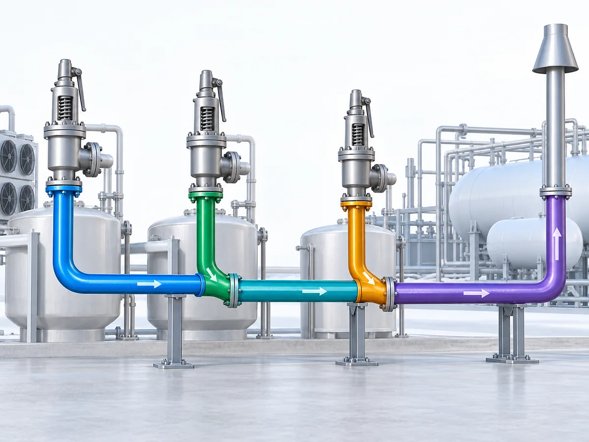
A shared system can be represented conceptually as connected branches and downstream segments:
PRV-A ── Branch A ─┐
├── Header Segment 1 ─┐
PRV-B ── Branch B ─┘ ├── Header Segment 2 → Destination
│
PRV-C ─────── Branch C ──────────────────┘
If A and B are active, Header Segment 1 can carry their combined flow. If C also enters farther downstream in the governing scenario, the flow through Header Segment 2 changes.
The entire header therefore does not necessarily carry one constant flow rate.
4. Establish the flow through each segment
For each credible relief scenario, identify which relief devices are active, what flow enters at each branch, and what combined flow continues through each downstream segment.
This step converts a list of valves into a hydraulic network. If two branches enter upstream of a given header segment, that segment may carry the combined flow for the governing scenario; a different downstream segment may carry an additional source. That changing flow is why the header should not be treated as one lumped line.
5. Evaluate pressure through the actual network
Use the applicable refrigeration relief-piping calculation basis and enough installed geometry to represent the real path.
The IIAR common-header technical paper provides an engineering example that represents a relief vent system as connected PRVs, branches, fittings, junctions and downstream piping rather than treating the header as a single lumped pipe.
Depending on the applicable method, the network representation can require pipe dimensions, actual run length, fittings, tees and junctions, reducers, relevant elevation effects, and the final downstream or terminal pressure.
A P&ID can show connectivity, but it may not contain enough installed geometry to establish an accurate piping-loss result. A piping isometric or equivalent installed-route data is often needed when lengths, fittings and elevation affect the calculation.
6. Determine the downstream condition at each relief valve
Do not stop at the pressure calculated at the end of the common header.
Each active valve has its own branch location and branch resistance. Valves can also have different capacities, set-pressure conditions or performance limitations.
As a result, valves connected to the same header do not necessarily experience identical outlet conditions.
7. Verify each valve separately
The header calculation becomes useful only when the calculated outlet condition for each valve is checked against that valve’s applicable operating and performance basis.
One valve can therefore become the controlling constraint even when another valve connected to the same common header remains within its acceptable basis.
Reusable review sequence: scenario → active sources → segment flows → network pressure → pressure at each valve outlet → valve-specific check.
If another credible scenario produces a different source combination, repeat the network review for that case rather than assuming the first result governs automatically.
Check the Actual Relief Valve Against the Calculated Downstream Condition
A discharge-piping calculation tells you the downstream condition. It does not, by itself, tell you whether the selected relief valve is acceptable.
Refrigeration safety-relief valves are not all equally sensitive to back pressure. Danfoss documentation, for example, describes its SFA refrigeration relief-valve family as back-pressure dependent, while the BSV 8 is described as back-pressure independent for its defined product application. These examples show why the actual valve evidence matters; they are not ZOBAI product claims.
| Known result | Evidence needed next |
|---|---|
| Calculated outlet/back-pressure condition | Actual manufacturer’s allowable operating basis |
| Selected valve configuration | How that design responds to downstream pressure |
| Set-pressure basis | Whether the downstream condition changes the expected valve behavior |
| Rated/certified capacity | Any applicable manufacturer adjustment or piping limitation |
| Common-header scenario | Confirmation that the valve remains acceptable in each governing case |
A label such as back-pressure independent should not be interpreted as unlimited back pressure. It describes a product characteristic within a defined design envelope.
Likewise, a balanced configuration should not be treated as a substitute for calculating the discharge system. A balanced valve may reduce the influence of outlet pressure in an appropriate design, but it does not establish the common-header flow, remove branch losses or prove that the final discharge arrangement is acceptable.
Verification sequence: calculate downstream condition → identify exact valve → check manufacturer and applicable certified basis → determine whether the candidate remains within its documented envelope.
If the necessary product data are missing, do not borrow the allowable limit from another manufacturer’s valve or from a different valve architecture. Keep the candidate unresolved until the relevant evidence is available.
Illustrative engineering scenario: a replacement valve is selected because its inlet and outlet connections match the existing valve. If the new model has a different certified capacity, back-pressure characteristic, or manufacturer piping limitation, a connection-size-only replacement review can miss a real system mismatch. The preventive action is to verify the replacement model’s certified/declared capacity basis and outlet-pressure limits against the existing branch and header. This is illustrative, not a reported ZOBAI project.
For a broader explanation of conventional and balanced configurations, see ZOBAI’s back pressure balanced safety valve guide.
Verify the Final Discharge Path and Physical Installation
A hydraulic calculation can pass while the installed relief path still has unresolved issues. Before treating the downstream system as complete, close three additional areas: destination, flow-path integrity, and mechanical installation.
Discharge destination changes the design boundary
First establish where the refrigerant goes.
Depending on the system, the relief path may terminate at an atmospheric discharge point, at a lower-pressure part of the refrigeration system, at a recovery or treatment system, or at another defined project interface.
Those destinations should not be assumed equivalent.
The refrigerant also matters. The official ASHRAE Standard 15 scope excludes ammonia R-717, while closed-circuit ammonia refrigeration has a separate IIAR standards path where that framework applies.
For ammonia-specific design context, use ZOBAI’s IIAR ammonia refrigeration standards guide.
IIAR’s 2025 interpretation on internally relieved safety-relief piping distinguishes internal vapor relief from atmospheric relief arrangements and confirms that internal vapor relief can be permitted within the interpreted IIAR 2-2021 framework. An atmospheric-discharge method should therefore not automatically be applied to an internal discharge path.
The project-level question is where the relieved refrigerant goes and which current adopted standard, manufacturer requirement, project specification or authority having jurisdiction governs that destination.
Use the standard that actually owns the service
For refrigeration-system relief piping, ISO 24664:2024 is directly relevant to relief-device capacity and associated inlet/outlet line pressure-loss calculations. For stationary systems within its scope, ASHRAE Standard 15 provides the refrigeration safety framework, but its current published scope excludes R-717. For closed-circuit ammonia refrigeration, IIAR standards are the more direct design/installation authority where adopted or required by the project or AHJ; IIAR identifies IIAR 2 as the safe-design standard and IIAR 4 as the installation standard, including overpressure-protection relief piping systems.
API 520 and ASME pressure-relief requirements may still matter when the protected equipment or project invokes them, but they should not be substituted automatically for the refrigeration-specific authority path. API itself describes API 520 Part II as installation guidance for pressure-relieving devices in refineries.
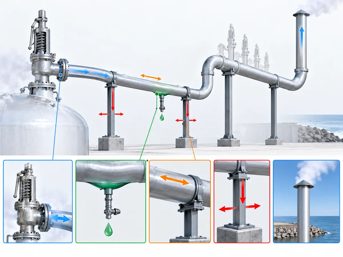
Check low points and possible liquid accumulation
The discharge path must remain capable of performing its intended function.
Depending on the refrigerant, temperature, routing and environment, moisture or condensate can become relevant at low points. As a scoped U.S. example, OSHA 29 CFR 1910.111 includes condensate-drainage provisions for relief-discharge piping within the anhydrous-ammonia installations covered by that regulation.
That scoped example does not establish one universal drainage rule for every refrigeration system. It does support a practical engineering check: could liquid accumulate in a way that changes or obstructs the intended relief path?
If that condition is credible, the project-specific drainage arrangement needs to be reviewed against the applicable design basis.
Illustrative engineering scenario: a cold vent line contains a low point where condensate or other liquid can collect between relief events. The line can look unobstructed on a P&ID while the installed geometry creates a liquid pocket. The preventive action is to review actual routing, low points, drainage provisions, and the applicable refrigerant/jurisdiction requirements. This is illustrative, not a reported installation failure.
Check reaction loads, support and thermal movement
Relief discharge creates mechanical effects as well as hydraulic ones.
Pressure-relief-valve manufacturer technical guidance identifies discharge reaction and transferred piping loads as installation considerations. ZOBAI’s own safety-valve catalog likewise identifies outlet-piping concerns including discharge loading, discharge-pipe expansion, vibration and misalignment.
Depending on the installation, the review may need to address:
- discharge reaction;
- piping supports;
- thermal expansion or contraction;
- flexibility;
- misalignment;
- vibration;
- loads transferred into the valve or protected equipment.
The solution is installation-specific. A flexible connector, for example, may be permissible in a particular design, but it is not a universal requirement and does not replace a complete support and piping review.
Hydraulic acceptance is necessary, but it is not the same as final installed-system acceptance.
What to Include in an Engineering Review or RFQ
An effective refrigeration relief-system inquiry should allow the supplier or engineering reviewer to reconstruct four things without guessing: the relief duty, the valve, the discharge network, and the final downstream boundary.
Relief duty
- protected equipment;
- credible relief scenario;
- required relieving flow;
- set-pressure basis;
- relieving pressure and temperature basis where applicable.
Refrigerant and state
- refrigerant;
- composition where relevant;
- vapor, liquid or other relieving state;
- other fluid conditions required by the selected calculation method.
Relief-valve data
- manufacturer;
- model;
- set pressure;
- rated or certified capacity basis;
- inlet and outlet connections;
- valve configuration;
- manufacturer limits related to back pressure or discharge piping.
Individual discharge branch
- pipe dimensions;
- run length;
- fittings;
- reducers;
- relevant elevations;
- branch connection into the common header.
Common header
- all connected relief devices;
- branch locations;
- header segments and dimensions;
- credible simultaneous-relief scenarios;
- other sources that can pressurize the shared header.
Final discharge interface
State whether relief is to atmosphere, another pressure level in the refrigeration system, a recovery or treatment system, or another defined destination. Also provide the terminal pressure and applicable jurisdiction, adopted standard or project specification.
Physical installation
Where relevant, include supports, low points and drainage arrangement, flexibility provisions, significant thermal movement and routing constraints.
Procurement checks that prevent a false “like-for-like” replacement
For a replacement or new purchase, do not stop at manufacturer, connection size, and set pressure. Confirm the required relieving flow, the valve’s capacity/rating basis, refrigerant and phase suitability, back-pressure limitations, discharge connection and piping assumptions, applicable certification/documentation, and any installation restrictions that affect the connected header. If any of those inputs change, the old header calculation should not be assumed valid without review.
A useful request is therefore more specific than “Please quote a refrigeration relief valve for this header.” A better technical handoff contains relief duty + refrigerant/state + valve data + branch geometry + header network + governing relief scenario + discharge destination + applicable design basis.
Need to review a refrigeration relief-valve candidate? Prepare the relief duty, refrigerant and relieving state, valve data, outlet branch, common-header arrangement, governing relief scenario, discharge destination and applicable project basis. Submit those inputs through Ask a Safety Valve Engineer so the valve candidate and RFQ requirements can be reviewed against the supplied duty. Final system piping and code acceptance remain project-specific.
Frequently Asked Questions About Refrigeration Relief Discharge Piping
Does the relief valve outlet size determine the discharge pipe size?
No. The outlet connection is only one physical interface. The discharge path still has to be evaluated for the applicable relief flow, piping geometry, downstream pressure, common-header interaction, and the exact valve’s piping/back-pressure limits.
Should every relief valve connected to a common header be assumed to discharge at the same time?
Not automatically. The common-header design basis should identify the credible simultaneous or coincident relief scenario for the protected equipment and project. Depending on the system, adding every connected device can be unnecessarily conservative, while considering only the largest valve can be non-conservative. The scenario needs an engineering basis.
How does back pressure affect a refrigeration safety-relief valve?
Back pressure can change the outlet condition against which the valve operates. The effect depends on valve design and manufacturer data. Built-up back pressure develops during discharge; superimposed back pressure is present before the valve opens. The calculated downstream condition should be checked against the exact valve rather than a generic percentage taken from another valve family.
Is ASHRAE Standard 15 the main authority for ammonia R-717 relief piping?
No. The current published ASHRAE Standard 15 scope excludes ammonia R-717 systems. Closed-circuit ammonia refrigeration follows the applicable IIAR standards, jurisdictional requirements, project specifications, and AHJ decisions. ASHRAE 15 remains relevant for systems within its own scope.
Can an internally relieved vapor valve use the same piping method as a valve discharging to atmosphere?
Not automatically. IIAR’s 2025 interpretation on internally relieved safety-relief piping confirms that internal vapor discharge can be permitted within the interpreted IIAR framework and highlights that atmospheric-discharge assumptions do not simply transfer to every internal-relief arrangement. The terminal pressure and receiving system have to be part of the calculation basis.
When should a refrigeration relief header be re-evaluated?
Re-evaluate the header when a change can alter relief flow, source combinations, downstream resistance, terminal pressure, or valve acceptance—for example, adding a relief branch, changing valve model or capacity basis, rerouting piping, changing the discharge destination, or changing refrigerant/service conditions. The extent of re-evaluation depends on the applicable project and code basis.
Why is certified or documented relieving capacity more important than connection size?
Connection size tells you how the valve physically connects to the piping. It does not prove how much the valve can relieve under the applicable rating basis. The relief duty has to be compared with documented valve capacity, and the installed outlet system still has to be checked for back pressure and other downstream effects.