Selecting a safety relief valve for a pressurized LPG storage vessel should start with the relief duty, not with a valve model. Before a supplier can review a device, the project needs to establish what equipment is protected, what condition is being relieved, why overpressure can occur, what required relieving duty has already been determined, …

Selecting a safety relief valve for a pressurized LPG storage vessel should start with the relief duty, not with a valve model. Before a supplier can review a device, the project needs to establish what equipment is protected, what condition is being relieved, why overpressure can occur, what required relieving duty has already been determined, and what downstream and service conditions the valve will face.
A practical selection sequence is therefore: confirm the tank class and protected boundary; establish the LPG relieving state and credible overpressure cases; carry forward the required relieving capacity from the responsible relief calculation; define the discharge and back-pressure conditions; verify service and component compatibility; then release a technically complete RFQ for product-specific review.
The phrase “LPG storage tank” does not establish one universal valve configuration, relief basis, material choice, or required duty. If a decision-critical input is still unknown, selection should remain open rather than being completed by assumption.
Confirm the LPG Tank Class and the Protected Pressure Boundary
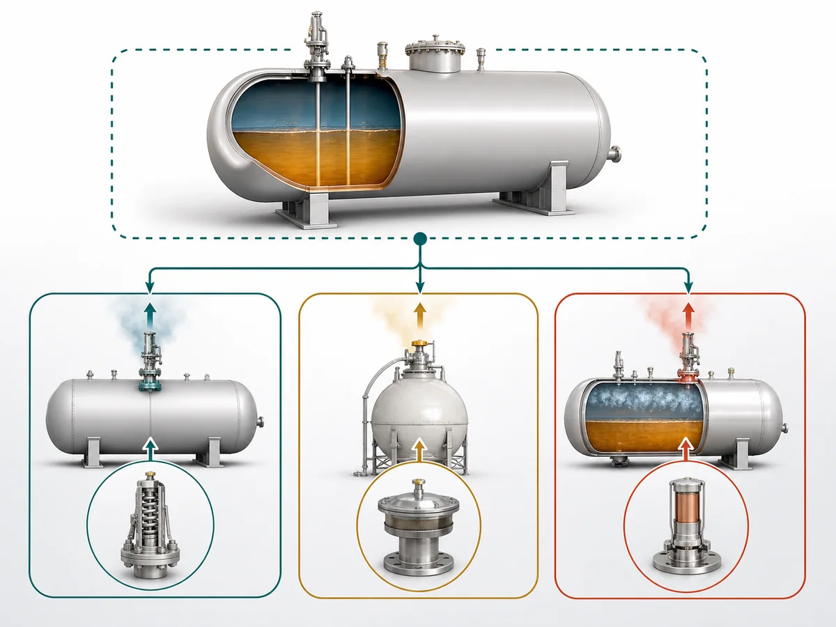
The first decision is whether this article applies to the equipment at all. Its scope is a pressurized LPG storage vessel requiring positive-pressure overpressure protection. “Storage tank” by itself is not a sufficient equipment definition.
Pressurized LPG vessel vs other storage-tank architectures
A safety relief valve on a pressurized vessel protects a defined pressure-containing boundary against excessive positive pressure. That is a different duty from normal pressure/vacuum breathing or vacuum protection on another tank architecture.
It is also separate from thermal relief of LPG trapped between closed isolation points. The medium may be the same, but the protected volume, initiating condition, and relief duty are different.
Before reviewing a valve: Identify the protected vessel and pressure-containing volume. If the duty is vacuum protection, normal tank breathing, trapped-liquid relief, or another storage architecture, route the problem to its separate engineering owner.
OSHA public LPG storage requirements support the principle that the vessel relief device must communicate with the pressure boundary it is intended to protect. The exact installation requirements remain dependent on the applicable project and jurisdiction.
What the safety relief valve is actually protecting
Before moving to pressure, capacity, or materials, the project should be able to identify:
- the vessel being protected;
- the pressure-containing space connected to the relieving path;
- the connection through which relief occurs;
- whether any adjacent equipment or isolated liquid volume needs independent protection;
- whether the storage system belongs to a different relief architecture.
This boundary check prevents a downstream supplier from being asked to solve the wrong protection problem with the right type of product.
When this article is the wrong selection route
This article does not own refrigerated or low-pressure LPG storage design, pressure-vacuum protection, normal breathing, vacuum protection, or trapped-liquid thermal relief. Those topics can be mentioned only to identify that the current selection route is wrong.
Continue with this selection route only when the protected equipment is confirmed as a pressurized LPG storage vessel and the required function is positive-pressure safety relief.
Define the LPG Relieving State and the Credible Overpressure Cases
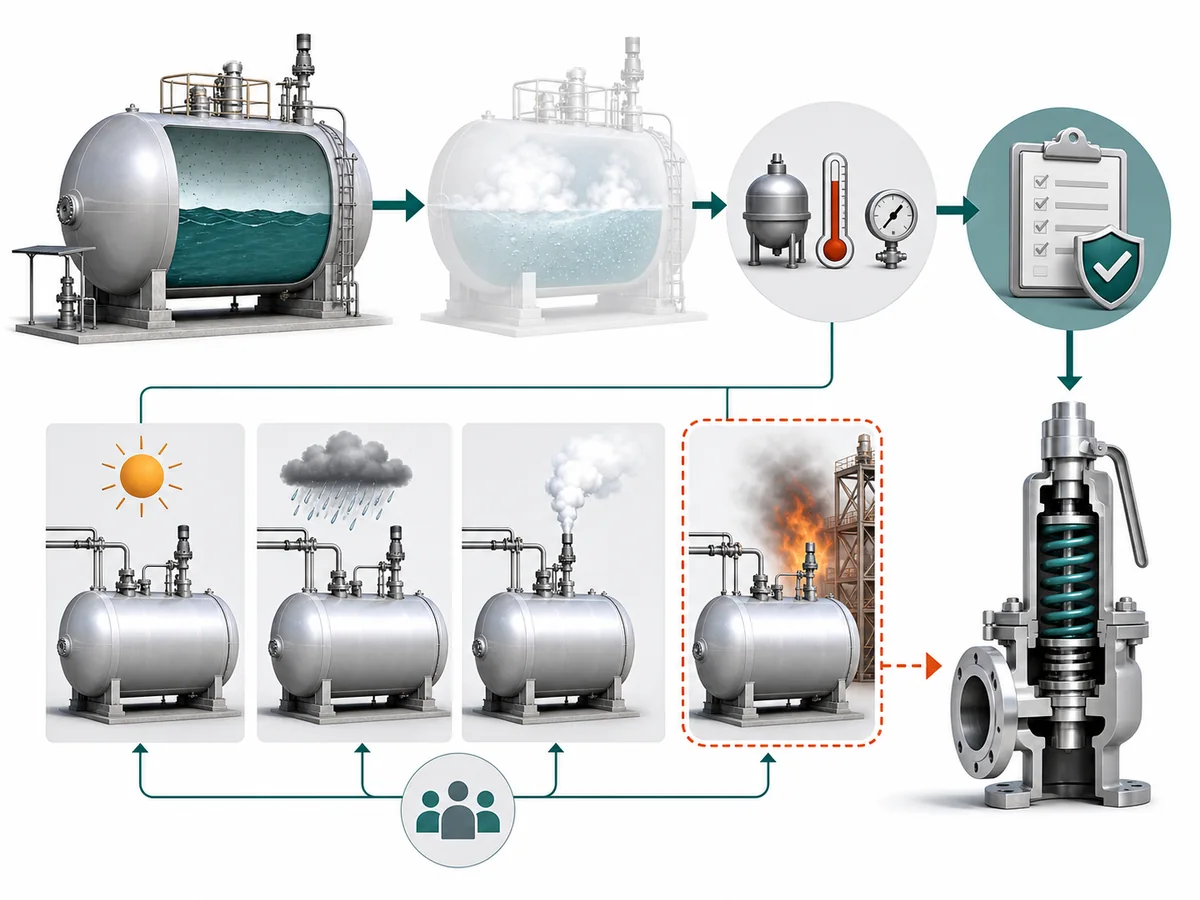
After the equipment boundary is known, the next question is not simply “What fluid is stored?” It is what condition reaches the relief device, and under which credible event?
Stored LPG state is not automatically the relieving state
LPG may be stored as a liquefied product, but that does not establish the fluid condition that should be carried into relief-device review. The relieving state follows from the actual scenario and relieving conditions, not from the product name alone.
That distinction matters because the approved sizing work and the later device review must refer to the same relieving basis. The purpose here is not to calculate phase behavior; it is to prevent an assumed phase from silently entering the RFQ.
If the relieving state is unresolved, final device selection remains unresolved. The RFQ should identify the relieving state from the approved project basis.
Authority basis: HSE relief-system guidance supports distinguishing fluid condition as part of relief-device engineering.
Identify credible cases before comparing valves
A credible overpressure case is an event or operating condition that the responsible project analysis has determined requires protection. A scenario is not made credible merely because it appears on a generic checklist, and a credible scenario is not automatically the governing one.
HSE LPG major-hazard guidance supports systematic, installation-specific scenario assessment and identifies overfilling as one situation that may lead to pressure-relief-device discharge. That supports evaluating the case where relevant; it does not support declaring it governing for every LPG vessel.
For every case carried into valve selection, confirm that it is credible for the installation, the project has established whether it governs the required duty, and the relieving conditions used for valve review correspond to that case.
When fire exposure belongs in the relief basis
External fire exposure can raise the pressure of a bulk LPG vessel, so it can form part of the relief basis when the installation makes that scenario credible. HSE LPG guidance also shows why layout and escalation matter: a fire originating elsewhere can expose another LPG vessel.
That evidence supports treating fire as a conditional engineering case. It does not support treating fire as universally applicable or universally governing simply because LPG is stored.
For fire exposure, verify two things before progressing: that the scenario is credible for the installation and that the responsible relief analysis has established the corresponding required duty. If either remains unresolved, valve selection should not invent the missing fire basis.
Detailed fire-case analysis remains outside this article.
Use the Required Relieving Capacity as an Input—Do Not Recalculate It Here
Once the governing relief basis is established, the selection process needs the required relieving capacity produced by the responsible relief analysis. This article receives that requirement; it does not generate it.
Required capacity and valve selection are different decisions
The engineering sequence contains separate decisions. First, the project identifies credible overpressure causes and establishes the relieving duty. Then a proposed device is reviewed against that duty and its associated relieving conditions.
Authority basis: API pressure-relieving-systems guidance and Curtiss-Wright/Farris technical ordering documentation support this separation between defining the duty and reviewing a proposed device.
This prevents a common responsibility gap: asking a supplier to select a valve when the project has not yet defined what the valve is required to relieve.
Responsibility boundary: A proposed valve can be reviewed against a defined relieving requirement. It cannot supply the missing engineering basis for an undefined requirement.
What the selection step needs from the approved relief basis
For selection purposes, the project should carry forward:
- the governing relief case;
- the required relieving capacity associated with that case;
- the relieving fluid state;
- the relieving conditions needed for device review.
The sizing calculation, its assumptions, and its calculation method remain with the separate sizing owner. The selection task is narrower: determine whether the proposed device has product-specific evidence supporting the stated duty under the stated conditions.
Stop if the governing case or required capacity is unresolved
The following are not substitutes for a defined relieving requirement:
- the vessel connection size;
- the nominal size of an existing valve;
- a generic valve associated with LPG service;
- a valve used on another project;
- capacity information generated for different relieving conditions.
Selection remains open if the governing case, required relieving capacity, or corresponding relieving conditions have not been established.
Check the Discharge Path and Back-Pressure Conditions
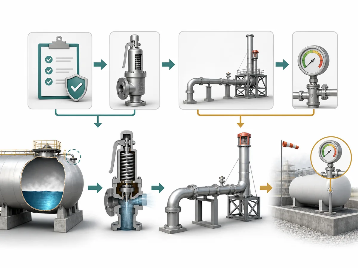
A safety relief valve is part of a relief path, not an isolated inlet-side component. The downstream arrangement can affect both safe disposal and the operating conditions seen by the valve.
Where the relieved LPG is intended to go
The project should identify the intended discharge destination before final valve review. The route may be dedicated or may connect to another disposal or collection system, but this article does not prescribe which arrangement is correct.
The selection question is whether the route is sufficiently defined for the proposed valve to be reviewed against the actual outlet condition.
Authority basis: API pressure-relief-system guidance treats downstream piping and disposal systems as part of relief-system engineering. OSHA LPG requirements provide jurisdiction-specific support for considering discharge routing and common relief arrangements.
Why outlet conditions belong in preliminary valve selection
Back pressure is one reason the downstream condition cannot be left undefined. HSE relief-system guidance supports that back pressure can affect valve operating behavior, stability, and capacity.
For procurement, this changes the required information. The supplier needs the downstream condition established by the project rather than an assumption that the outlet is unrestricted.
Before product review, state whether downstream pressure is present or expected during relief and provide the project basis for that condition. The phrase “back pressure” alone does not establish which valve construction is appropriate.
When the discharge system requires separate hydraulic review
If the discharge pressure depends on a shared or constrained downstream network, valve selection may depend on system hydraulics that are not owned by this article.
The trigger for separate system review is not merely the existence of a header or connected network. The issue is whether the relevant outlet condition for the proposed valve depends on the scenario-specific behavior of that interconnected system and has not otherwise been established.
Hold final selection when the downstream pressure condition needed for valve review cannot be established without separate relief or disposal-system analysis.
Verify Material and Service Compatibility
“Suitable for LPG” is not a complete compatibility statement. A proposed valve has to be checked against the actual service definition and against the components exposed to that service.
Define the actual LPG service, not just the label “LPG”
The project should provide enough service information for a product-specific compatibility review. Relevant inputs include:
- the LPG service as defined by the project;
- the relieving state;
- the operating and relieving pressure conditions;
- the operating and relieving temperature conditions;
- project-specific material restrictions;
- environmental or corrosion conditions relevant to the installed device.
Emerson pressure-relief-valve technical guidance supports fluid type, temperature, pressure requirements, and material compatibility as selection inputs. These factors define what must be checked; they do not establish a universal material answer.
Check wetted and non-metallic component compatibility
Compatibility review should not stop at the pressure-containing body. OSHA LPG requirements and Emerson LPG technical guidance extend the suitability question to exposed internal and non-metallic components such as seats, packing, gaskets, diaphragms, and other wetted elements relevant to the offered construction.
Compatibility review should proceed from service to construction: define the submitted service conditions first, then require the supplier to identify the actual exposed component materials in the proposed device and confirm their suitability for those conditions.
Do not convert a generic material preference into project suitability
A familiar body material, trim description, or generic LPG label does not by itself establish complete valve suitability.
Project acceptance still depends on the offered device as a complete construction, including relevant metallic and non-metallic components, the actual relieving conditions, and any purchaser material restrictions.
Evidence boundary: This article defines the compatibility information that must be checked; it does not convert a generic material preference into project-specific approval.
Build the RFQ Package and Apply Evidence Stop Conditions
The RFQ is the point where engineering responsibility and supplier verification should become explicit. The project defines the relief duty and acceptance basis; the supplier confirms a proposed valve against that information.
Minimum technical inputs before supplier review
| Decision Item | Project / Buyer Must Establish | Supplier Must Confirm for the Proposed Device |
|---|---|---|
| Protected equipment | The vessel, tank class, and protected pressure boundary. | That the proposed device is being reviewed for the stated protection duty. |
| Relief basis | The credible and governing overpressure case and the applicable project acceptance basis. | That the proposed device review uses the submitted basis rather than an assumed alternative. |
| Relieving duty | The required relieving capacity and the relieving conditions associated with it. | Product-specific capacity evidence against the submitted duty. |
| Fluid condition | The LPG service and relieving state. | That the offered device is reviewed against those stated conditions. |
| Downstream condition | The discharge destination and relevant downstream or back-pressure basis. | That the proposed device is suitable for the submitted outlet condition. |
| Compatibility | Service conditions, material restrictions, and environmental requirements relevant to selection. | The actual construction and exposed component materials of the proposed device and their suitability for the submitted service. |
| Interfaces | The required inlet and outlet interfaces. | The actual interfaces of the offered device. |
| Documentation | The purchaser’s required evidence and acceptance documentation. | Which product-specific documents are actually available for the offered device. |
This responsibility split is supported by Curtiss-Wright/Farris and Emerson manufacturer engineering documentation: the application supplies the process and relief conditions first, after which a specific device can be evaluated and documented.
What the supplier must confirm rather than the buyer assume
The supplier’s role begins with a defined duty. For the offered valve, the supplier should confirm the actual configuration and the product-specific evidence needed to compare that configuration with the submitted requirements.
That may include:
- the proposed device configuration;
- capacity evidence relevant to the submitted relieving duty;
- actual construction and component materials;
- suitability for the stated service and downstream conditions;
- actual inlet and outlet interfaces;
- relevant product limitations;
- the product documentation actually available.
The supplier should not be treated as the silent owner of an undefined vessel relief basis. Product evidence verifies a proposed device; it does not replace the missing process-engineering inputs.
When selection must remain open instead of naming a valve
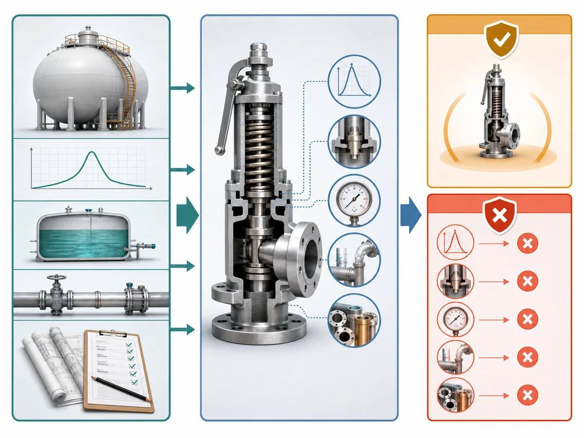
Final device selection should remain open whenever a missing input prevents the proposed valve from being compared with a defined duty.
- The protected equipment or pressure boundary is unresolved.
- The credible or governing relief case is unresolved.
- The relieving state is unresolved.
- The required relieving capacity is not established.
- The relevant downstream condition is undefined.
- The service or compatibility basis is insufficient for component review.
- A project acceptance or documentation requirement that affects device selection remains undefined.
RFQ responsibility: Project engineering defines the duty; the supplier verifies a proposed valve against it. An RFQ may be used to request clarification, but missing decision-critical inputs keep the technical selection open.