Safety Valve Troubleshooting A safety valve can start leaking after a lifting-lever or try-lever test when the manual opening disturbs the disc-to-seat interface. The first checks are trapped debris, an already marginal seating surface, and incomplete return of the disc, spindle, guide or lifting mechanism. Leakage after the test does not by itself prove that …

Safety Valve Troubleshooting
A safety valve can start leaking after a lifting-lever or try-lever test when the manual opening disturbs the disc-to-seat interface. The first checks are trapped debris, an already marginal seating surface, and incomplete return of the disc, spindle, guide or lifting mechanism. Leakage after the test does not by itself prove that set pressure has changed. If these directly disturbed parts do not explain the symptom, expand the review to operating pressure, inlet conditions, discharge back pressure and piping loads.
Quick answer:
after an intentional lifting-lever test, diagnose the seat and moving assembly first. Check for debris, damaged or marginal seating surfaces, and incomplete mechanical return. Do not adjust the spring from leakage alone. Use operating-pressure and piping checks only as the next diagnostic tier, then use the appropriate controlled test before deciding on repair or replacement.
after an intentional lifting-lever test, diagnose the seat and moving assembly first. Check for debris, damaged or marginal seating surfaces, and incomplete mechanical return. Do not adjust the spring from leakage alone. Use operating-pressure and piping checks only as the next diagnostic tier, then use the appropriate controlled test before deciding on repair or replacement.
Page boundary:
this guide covers leakage that begins after intentional manual lifting.
Leakage following an automatic pressure-relief event
involves a broader set of dynamic and installed-system causes and should be diagnosed as a separate troubleshooting condition.
this guide covers leakage that begins after intentional manual lifting.
Leakage following an automatic pressure-relief event
involves a broader set of dynamic and installed-system causes and should be diagnosed as a separate troubleshooting condition.
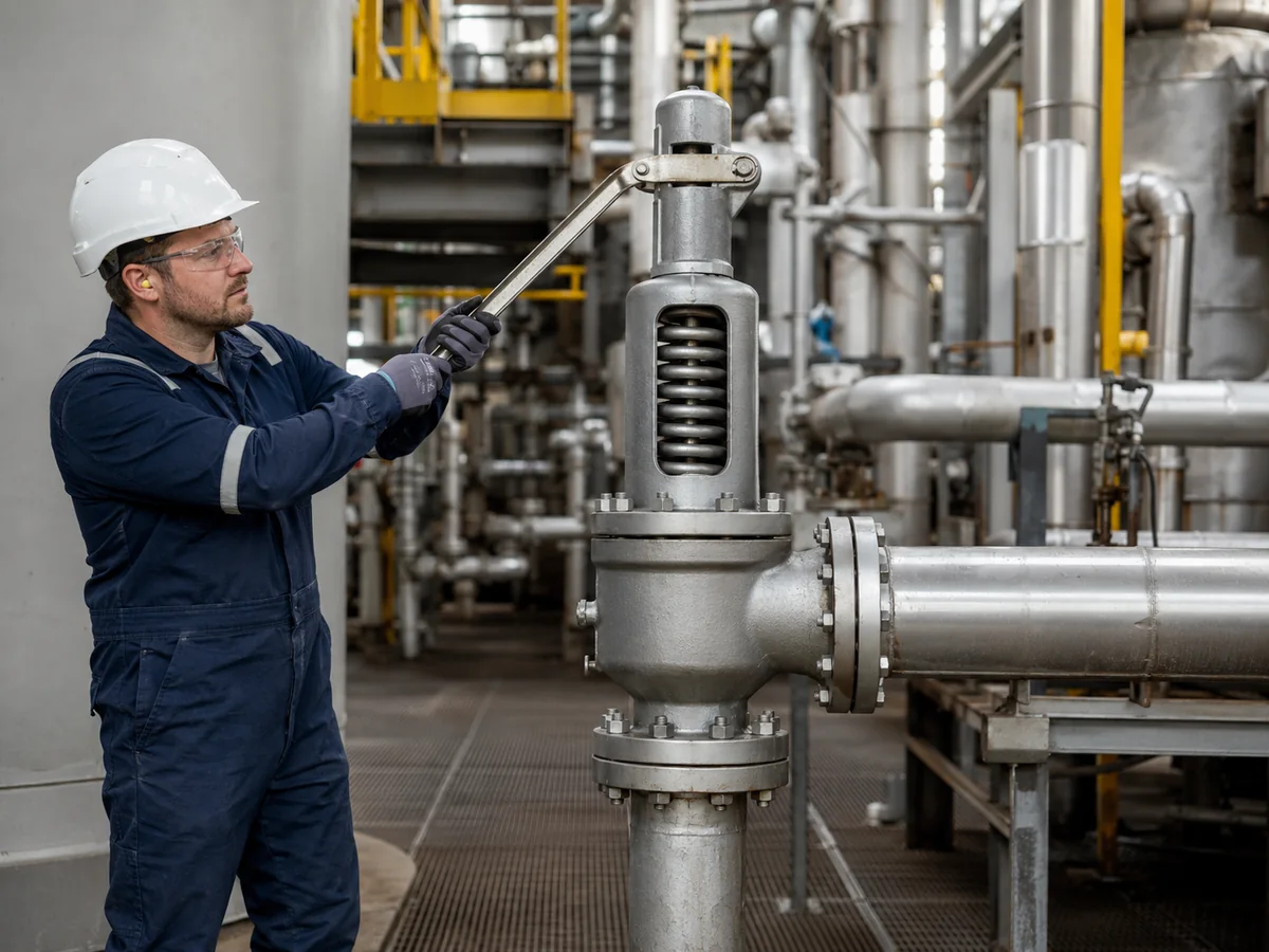
Illustrative industrial scene; not a specific ZOBAI installation, test record or product-certification image.
Start With Evidence: The Diagnostic Priority After a Lever-Test Leak
The main troubleshooting error is moving directly from “the valve leaks” to “the spring setting is wrong.” When leakage begins immediately after intentional manual lifting, the first diagnostic tier should stay close to what was physically disturbed: the seating interface, the moving assembly and the lifting mechanism.
| Priority | What to Establish | Why It Matters | Unsafe Assumption to Avoid |
|---|---|---|---|
| 1 | Exactly when leakage started | Confirms whether the symptom appeared immediately after manual lifting. | Assuming the test permanently changed set pressure. |
| 2 | Whether the lever and moving assembly returned normally | Helps screen for friction, interference or incomplete reseating. | Assuming external lever position proves internal disc position. |
| 3 | Whether the service can carry scale, solids or deposits | Raises or lowers the likelihood of debris trapped at the seat. | Assuming repeated lever operation will clean the seat safely. |
| 4 | Whether known seat damage or prior repair exists | A marginal seat may become visibly leaky after being disturbed. | Assuming the lever test created all existing damage. |
| 5 | Whether seat and mechanical evidence explains the leak | If not, the investigation can then expand to process and piping conditions. | Starting with a full system redesign before checking the directly disturbed parts. |
Evidence rule:
do not adjust the spring, change set pressure or specify a replacement until the observed symptom has been separated from the original pressure-protection requirements.
do not adjust the spring, change set pressure or specify a replacement until the observed symptom has been separated from the original pressure-protection requirements.
What Changes Inside the Valve During a Lifting Lever Test?
In a typical spring-loaded safety valve equipped with a lifting device, the lever provides a mechanical means of moving the spindle and lifting the disc away from the nozzle seat. Process fluid then crosses the seating interface before the moving assembly returns toward the closed position.
Reliable reclosure depends on more than the visible lever returning to rest. The spindle and guide must move freely, the disc must return toward the intended seating position, and the seating surfaces must be sufficiently clean and undamaged to re-establish effective contact.
For the wider spring-force, disc-lift and reseating sequence, see
how a spring loaded safety valve works.
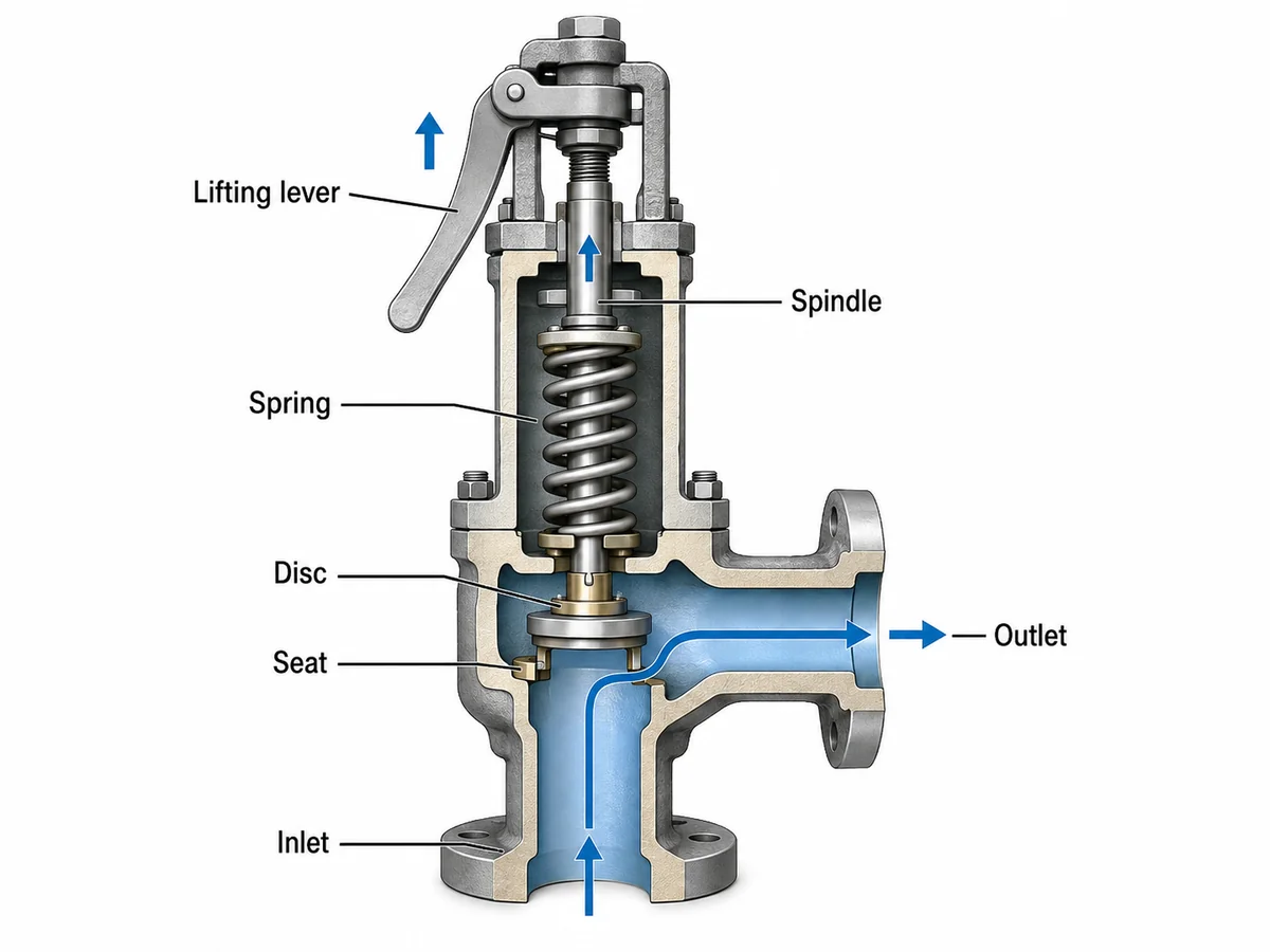
Simplified engineering illustration. Component geometry varies by valve design.
Engineering boundary:
a lifting device provides only a limited functional check under the conditions required by the applicable valve design, code, manufacturer instructions and site procedure. Manual lever movement does not prove set pressure, seat-tightness acceptance or relieving capacity.
a lifting device provides only a limited functional check under the conditions required by the applicable valve design, code, manufacturer instructions and site procedure. Manual lever movement does not prove set pressure, seat-tightness acceptance or relieving capacity.
Cause 1 — Dirt, Scale or Process Deposits Remain on the Seat
Seat contamination is one of the first conditions to consider when leakage begins immediately after a manual lifting event. Opening the valve allows process fluid to move across a seating interface that may have remained closed for an extended period.
Rust particles, scale, corrosion products, solids or process deposits can move with the fluid. If contamination remains between the disc and nozzle as the valve closes, complete sealing contact may not be restored.
The likelihood increases when the service can carry solids, corrosion products, crystallizing material, sticky deposits, polymerizing material or condensate. The exact risk still depends on valve design, medium, phase, temperature and process condition.
Composite engineering scenario for training
A spring-loaded steam safety valve had remained tight during normal service. After a scheduled manual lifting check, a small continuous leak became audible. One plausible mechanism is that scale or corrosion debris crossed the seating interface and remained between the disc and nozzle during closure.
The useful next step is to document the operating pressure, test condition and leakage behavior and determine whether controlled inspection or leakage testing is required. Changing spring compression would not address trapped debris.
Cause 2 — The Seating Surfaces Were Already Marginal or Became Damaged
Not every post-test leak comes from loose debris. The disc and nozzle seating surfaces may already have corrosion, erosion, scratches, uneven contact or previous maintenance damage.
A valve can appear tight before the test because the seating components have settled into one particular contact position. Once the disc is lifted and returned, the same imperfect contact may not be restored.
The lifting-lever test may therefore trigger visible leakage without being the original root cause of the seat condition.
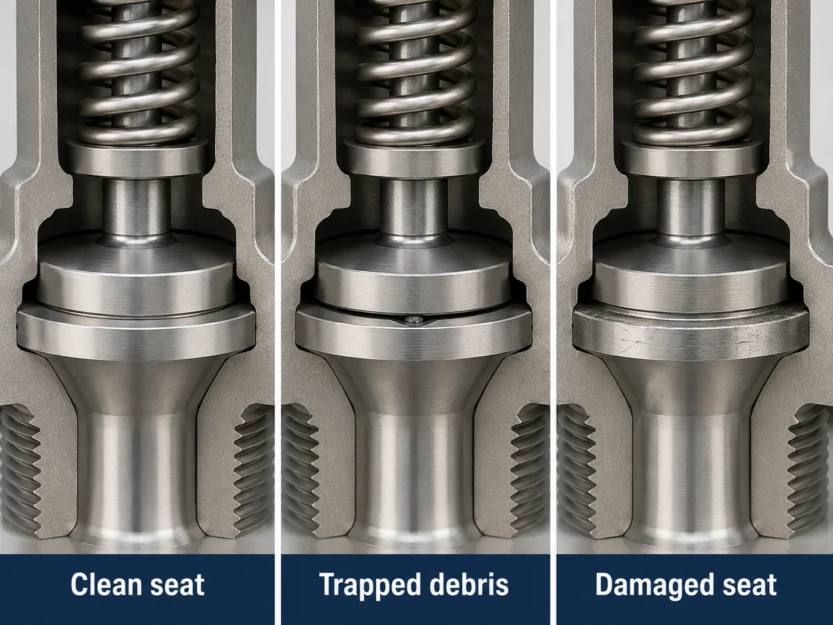
Simplified engineering illustration for troubleshooting education.
What evidence supports a seat-damage diagnosis?
Persistent leakage after operating conditions stabilize, known corrosion or erosion history, previous seat repair, visible damage during qualified inspection, or a controlled leakage test outside the applicable acceptance basis can support a seat-condition diagnosis.
External leakage alone is not enough to determine whether the correct repair is cleaning, lapping, component replacement or full valve replacement. The allowable repair method depends on the specific valve design, component condition, manufacturer requirements and applicable repair controls.
Cause 3 — The Disc, Spindle or Lever Mechanism Does Not Return Freely
The seating surfaces may be acceptable and the valve can still leak if the moving assembly fails to return to the intended closed position after manual lifting.
Possible mechanical contributors
- Guide contamination or corrosion
- Spindle friction or distortion
- Mechanical interference
- Misalignment
- Improper previous assembly
- Lifting-linkage return problems
Evidence worth checking
- Abnormal lever return
- History of previous overhaul
- Corrosion around moving parts
- Binding noted during controlled inspection
- Repeated post-maintenance leakage
The lever returning to its resting position does not prove that the disc, guide and spindle have fully returned internally. If movement is uncertain, inspection should follow the applicable manufacturer, site and qualified repair procedure.
For product-level context on spring-loaded valves fitted with a manual lifting device, see
lever safety valves.
Composite engineering scenario for training
A valve begins leaking immediately after a manual lever check. The external lever appears to return normally, but the valve has a recent overhaul history. The next investigation should include guide alignment, spindle condition and internal freedom of movement rather than assuming that the spring has weakened.
If binding or misalignment is confirmed, the corrective action belongs in a qualified repair and post-repair verification process.
Secondary Escalation Check — Operating Pressure and Reseating Conditions
If seat contamination, seating-surface damage and mechanical-return problems do not adequately explain the symptom, widen the investigation to the operating condition.
Safety-valve behavior depends on the relationship among normal operating pressure, set pressure, overpressure, accumulation, reseating pressure and blowdown. Operating too close to the valve’s stable closing region can contribute to simmering or continued leakage, but this is a broader operating-condition issue rather than a mechanism unique to the lifting-lever test.
Record actual operating pressure and process variability before drawing conclusions. The acceptable operating margin depends on valve design, medium, service stability, manufacturer data, applicable code and project requirements.
Keep the pressure terms separate:
MAWP is not set pressure; overpressure and accumulation use different reference pressures; blowdown describes the opening-to-reseating relationship; and none of these values by itself proves relieving capacity.
MAWP is not set pressure; overpressure and accumulation use different reference pressures; blowdown describes the opening-to-reseating relationship; and none of these values by itself proves relieving capacity.
Composite engineering scenario for training
Leakage starts after a manual lever test but then rises and falls with normal process-pressure swings. Once seat contamination and mechanical return have been screened, that pressure-dependent behavior is a reason to review operating margin and reseating behavior rather than automatically attributing the symptom to permanent seat damage.
Secondary Escalation Check — Installation, Back Pressure and Discharge Piping
When the directly disturbed seat and moving components do not explain persistent leakage, review the installed system. Inlet pressure loss, outlet resistance, back pressure, drainage and piping load can affect valve behavior and reclosure, but these are general system factors rather than causes created specifically by manual lever operation.
Inlet-side review
- Inlet pressure loss
- Piping cleanliness
- Mechanical alignment
- Recent piping modifications
Outlet-side review
- Superimposed back pressure before opening
- Built-up back pressure created by relief flow
- Discharge piping support
- Drainage and liquid pockets
- Mechanical load on the valve body
See the
safety valve installation guide
for detailed inlet, outlet, support and drainage review.
For the distinction between superimposed and built-up outlet pressure and the limits of balanced designs, see
back pressure and bellows.
Immediate Leak vs Persistent Leak — What the Timing Can Tell You
Leakage timing helps decide whether the first diagnostic tier should remain focused on seat disturbance and mechanical return or whether the investigation needs to expand. The timing is evidence for prioritization, not proof of root cause.
| Observation | First Direction | Evidence to Collect | Do Not Conclude Yet |
|---|---|---|---|
| Leakage starts immediately after manual lift | Seat contamination or incomplete reseating | Service cleanliness, lever return and event timing | That set pressure changed |
| Leakage remains continuous | Seat condition or mechanical return | Controlled test and qualified inspection | That lapping is automatically required |
| Leakage varies with process pressure | Escalate to operating-condition review | Operating pressure, set pressure and process stability | That the spring is weak |
| Leakage coincides with piping or header changes | Escalate to installed-system review | Back pressure, support, drainage and piping loads | That manual lifting caused the system problem |
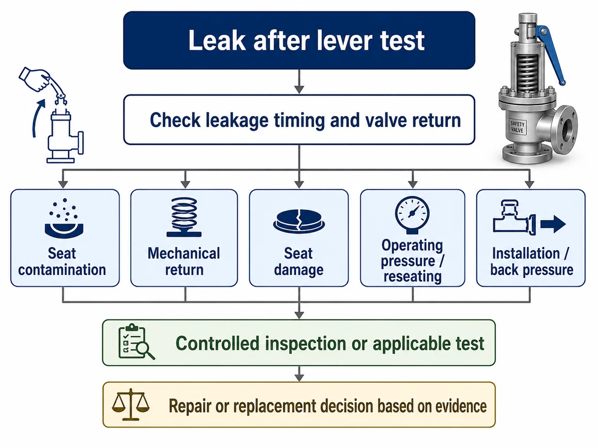
Simplified decision workflow. Actual inspection steps depend on the valve, process and applicable procedure.
What a Lifting Lever Test Can — and Cannot — Verify
A lifting device is a limited functional check under the conditions required by the applicable valve design, code, manufacturer instructions and site procedure. It should not be treated as a substitute for a controlled pressure, leakage or capacity test.
| Question | Can Manual Lever Operation Prove It? | What Is Needed Instead? |
|---|---|---|
| Can the relevant lifting mechanism move? | Limited functional indication only | Applicable inspection procedure and manufacturer instructions |
| Is actual set pressure correct? | No | Controlled set-pressure verification |
| Does the valve meet a seat-tightness acceptance criterion? | No | Applicable controlled seat-tightness test |
| Is documented relieving capacity adequate? | No | Manufacturer or certification capacity data under defined conditions |
| Is required capacity adequate for the governing relief scenario? | No | Relief-load determination plus capacity verification |
Required relieving capacity must be established from the governing relief scenario and checked against the selected valve’s documented or certified capacity basis. Connection size proves physical compatibility, not protection capacity. Capacity evidence is also medium- and condition-specific: steam, gas, liquid and two-phase capacity bases should not be interchanged without the applicable engineering and manufacturer data.
For the wider sizing distinction, see
safety valve sizing and certified relieving capacity.
When Seat Tightness Testing Becomes Necessary
Visible or audible leakage from an installed valve is an operating observation. A controlled seat-tightness test is performed under defined conditions and answers a different question.
API 527 addresses seat tightness of pressure relief valves where that standard is part of the applicable test basis. The adopted edition, valve design, test medium, pressure, seat construction and acceptance criteria still need to be confirmed for the actual project.
For detailed seat-test scope and RFQ interpretation, see
API 527 seat tightness testing.
Do not confuse the evidence:
seat tightness is not relieving capacity, and a set-pressure test is not a capacity test.
seat tightness is not relieving capacity, and a set-pressure test is not a capacity test.
What Not to Do After a Valve Starts Leaking
- Do not immediately change spring compression or set-pressure adjustment.
- Do not assume repeated lever operation is safe for every valve and service.
- Do not obstruct, cap or improperly isolate the discharge path to stop visible leakage.
- Do not assume successful lever movement proves relieving capacity.
- Do not replace the valve by connection size alone.
- Do not copy the existing set pressure to a replacement without reviewing the protected equipment and design basis.
- Do not perform uncontrolled internal repair on an installed valve.
Site isolation and repair decisions must preserve the required pressure-protection function. A leaking valve should not simply be isolated if doing so removes the required relief path; the approved plant procedure and responsible engineering authority must define the safe arrangement.
Troubleshooting Checklist Before Removing or Replacing the Valve
Before repair or replacement is selected, collect the lever-test evidence and the original pressure-protection data. Missing engineering inputs should remain “to be confirmed” rather than being inferred from connection size or a partial nameplate.
Lever-test event and immediate evidence
- Was the valve tight before the test?
- How was the lifting device operated?
- Did leakage begin immediately?
- Did the lever return normally?
- Is the service dirty, scaling or deposit-forming?
- Is there previous seat or repair history?
Protection and system data
- Protected equipment and governing relief scenario
- Medium and phase
- Operating pressure
- MAWP or design pressure
- Set pressure
- Required relieving capacity and capacity basis
- Relieving temperature
- Superimposed and built-up back pressure
- Inlet and outlet piping
- Nameplate and maintenance records
- Applicable code, adopted edition and project specification
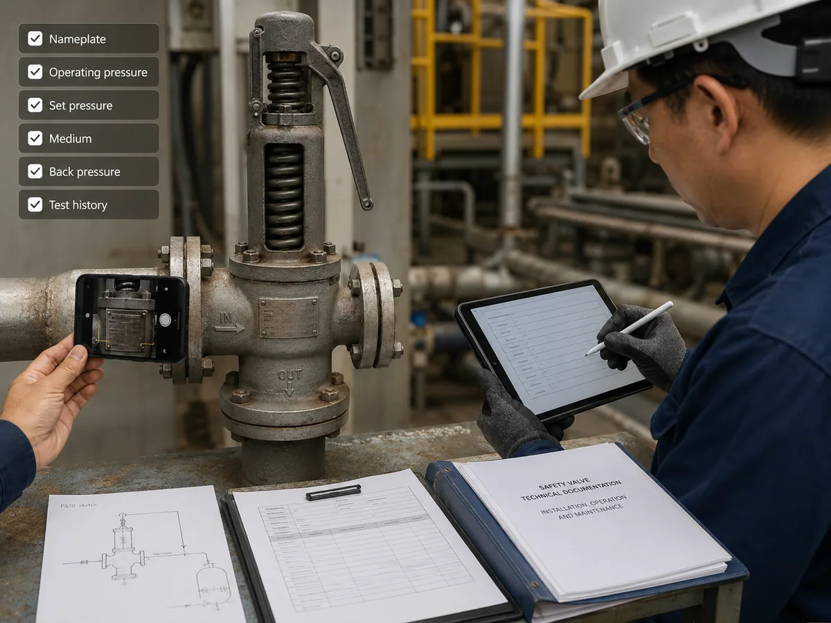
Illustrative inspection scene; displayed documents and values are not evidence of a specific ZOBAI project or test result.
Repair or Replace? Finish the Diagnosis Before Selecting the Remedy
For this specific failure mode, repair or replacement should come only after the lever-specific causes have been screened. If trapped debris, seat damage or incomplete mechanical return is confirmed, the repair decision can focus on the affected valve condition. If those checks do not explain the leakage, broader operating and installed-system causes should be addressed before assuming valve replacement will solve the problem.
| Evidence | Engineering Direction | What Still Needs Confirmation |
|---|---|---|
| Contamination suspected, no confirmed component damage | Controlled inspection or cleaning route where permitted | Seat condition and required post-maintenance test |
| Seat or nozzle damage confirmed | Qualified repair or component replacement review | Repair limits, component identity and final verification |
| Guide, spindle or lifting mechanism binding | Mechanical repair and post-repair verification | Cause of binding, correct assembly and freedom of movement |
| No lever-specific cause explains persistent leakage | Escalate to operating-pressure, back-pressure and installed-system review | Actual process and piping conditions |
| Valve condition, traceability or repairability is unacceptable | Develop a complete replacement specification | Original protection basis and documented replacement capacity |
When continued normal service needs escalation
Persistent leakage, abnormal lever or spindle return, suspected seating damage, uncertain repair history, evidence of binding, or inability to verify the valve against the required protection basis should trigger a site-controlled engineering and inspection decision. The exact remove-from-service or isolation action depends on the protected equipment and the approved means of maintaining required pressure protection.
Replacement material checks are part of the protection review
Do not treat body material alone as proof of service suitability. Confirm the wetted disc, nozzle, guide, spindle and trim; the spring environment; bellows material where fitted; and the seat or seal against the actual medium, phase, operating temperature, relieving temperature, corrosion, erosion, fouling and project requirements.
Connection size ≠ relieving capacity.
A replacement must preserve the actual pressure-protection basis, not merely fit the existing inlet and outlet connections.
A replacement must preserve the actual pressure-protection basis, not merely fit the existing inlet and outlet connections.
Engineering Decision Summary
- Confirm that leakage began after intentional manual lifting.
- Check seat contamination and disturbed seating surfaces first.
- Check lever, spindle, guide and disc return condition.
- Use controlled inspection or testing when the seat condition cannot be established externally.
- Only then widen the diagnosis to operating pressure, back pressure and piping conditions if necessary.
- Do not treat lever operation as proof of set pressure, seat tightness or capacity.
- Base repair or replacement on evidence and the original pressure-protection requirements.
- For replacement, re-confirm medium, phase, required capacity, relieving temperature, back pressure, materials, piping and the applicable project/code basis.
The objective is not simply to stop visible leakage. The objective is to restore confidence that the pressure-relief device can remain acceptably tight during normal operation and still provide the required pressure-protection function when demanded.
Technical Evidence and Official References
The following sources support the test-purpose and failure-mechanism boundaries used in this troubleshooting sequence. They do not prove certification or compliance of a specific ZOBAI valve.
API 527 — Seat tightness
API’s published standards listing identifies API Standard 527, Seat Tightness of Pressure Relief Valves, as a seat-tightness standard. Use the edition adopted by the actual project rather than assuming that every installation uses the same acceptance basis.
ASME PTC 25 — Performance testing
ASME PTC 25 addresses pressure-relief-device performance testing, including flow-capacity testing and in-service or bench testing. That scope is different from simply moving a manual lifting lever.
National Board — Leakage and repair mechanisms
National Board technical material identifies foreign material between the disc and seat, poor seating-surface preparation, spindle or guide problems and improper assembly as mechanisms that can contribute to leakage, binding or impaired valve function.
Current-code boundary
The National Board technical article cited here is historical engineering guidance rather than a substitute for the current NBIC, ASME Code, manufacturer instructions or jurisdictional requirements. Verify the requirements that apply to the actual valve and installation.
- American Petroleum Institute — Published Standards / API 527
- ASME — PTC 25 Pressure Relief Devices
- National Board — Typical Improper Repairs of Safety Valves
Standards and technical references explain test scope and engineering mechanisms; they do not establish that every ZOBAI model carries every code mark, certification or project approval.
Frequently Asked Questions
Why did my safety valve start leaking immediately after a lifting lever test?
Manual lifting separates the disc from its seat. Debris may become trapped on the seating surfaces, an existing seat defect may become apparent, or the moving assembly may fail to reseat fully. The actual cause should be verified before adjustment.
Can dirt on the seat cause leakage after a try-lever test?
Yes. Foreign material between the disc and seat can prevent complete contact and may contribute to further seating-surface damage.
Does leakage after a lever test mean the set pressure has changed?
No. Leakage after manual lifting does not by itself prove that set pressure has changed. Set-pressure verification requires the appropriate controlled test and procedure.
Can I operate the lifting lever again to stop the leak?
Do not treat repeated lever operation as a universal cleaning method. Whether another manual operation is appropriate depends on valve design, service medium, pressure, manufacturer instructions, site procedure and applicable code.
Does a lifting lever test prove enough relieving capacity?
No. Manual movement does not prove required or certified relieving capacity. Capacity must be checked against the governing relief scenario, medium, relieving conditions, selected orifice and documented manufacturer or certification data.
When should seat tightness be tested?
Controlled seat-tightness testing may be appropriate when leakage persists or when inspection, repair, project or code requirements call for a defined leakage assessment. The applicable procedure and acceptance basis must be confirmed for the valve and project.
When should a leaking safety valve be removed for inspection or repair?
Persistent leakage, impaired mechanical return, suspected seat damage, corrosion, uncertain repair history or failure to meet the applicable test basis can justify qualified inspection or repair.
Engineering and Standards Limitation
A lifting-lever check, set-pressure verification, seat-tightness testing and relieving-capacity verification serve different purposes and must not be treated as interchangeable evidence.
Final repair or replacement decisions depend on the protected equipment, governing relief scenario, medium and phase, operating pressure, MAWP or design pressure, set pressure, required relieving capacity, relieving temperature, superimposed and built-up back pressure, inlet and outlet piping, wetted materials, spring and bellows condition where applicable, seat or seal construction, manufacturer data, applicable standard edition, project specification and local regulatory requirements.
Need to Diagnose Leakage After a Lever Test?
Send the protected equipment, relief scenario, medium and phase, operating pressure, MAWP or design pressure, set pressure, required capacity and basis if available, relieving temperature, back pressure, inlet/outlet piping, valve nameplate, material and seat information if known, maintenance history and a description of when the leakage began.