Risoluzione dei problemi della valvola di sicurezza Una valvola di sicurezza può iniziare a perdere dopo un test con leva di sollevamento o leva di prova quando l'apertura manuale disturba l'interfaccia disco-sede. I primi controlli sono detriti intrappolati, una superficie di sede già marginale e un ritorno incompleto di disco, stelo, guida o meccanismo di sollevamento. La perdita dopo il test non dimostra di per sé che …

Risoluzione Problemi Valvola di Sicurezza
Una valvola di sicurezza può iniziare a perdere dopo un test con leva di sollevamento o leva di prova quando l'apertura manuale disturba l'interfaccia disco-sede. I primi controlli sono detriti intrappolati, una superficie di sede già marginale e un ritorno incompleto di disco, stelo, guida o meccanismo di sollevamento. La perdita dopo il test non dimostra di per sé che la pressione di taratura sia cambiata. Se questi componenti direttamente disturbati non spiegano il sintomo, estendere la verifica alla pressione di esercizio, alle condizioni di ingresso, alla contropressione di scarico e ai carichi delle tubazioni.
Risposta rapida:
dopo un test intenzionale con leva di sollevamento, diagnosticare prima la sede e il gruppo mobile. Controllare la presenza di detriti, superfici di sede danneggiate o marginali e un ritorno meccanico incompleto. Non regolare la molla basandosi solo sulla perdita. Utilizzare i controlli di pressione di esercizio e delle tubazioni solo come livello diagnostico successivo, quindi eseguire il test controllato appropriato prima di decidere se riparare o sostituire.
dopo un test intenzionale con leva di sollevamento, diagnosticare prima la sede e il gruppo mobile. Controllare la presenza di detriti, superfici di sede danneggiate o marginali e un ritorno meccanico incompleto. Non regolare la molla basandosi solo sulla perdita. Utilizzare i controlli di pressione di esercizio e delle tubazioni solo come livello diagnostico successivo, quindi eseguire il test controllato appropriato prima di decidere se riparare o sostituire.
Confine pagina:
questa guida copre le perdite che iniziano dopo un sollevamento manuale intenzionale.
Perdita a seguito di un evento di scarico automatico della pressione
coinvolge un insieme più ampio di cause dinamiche e legate al sistema installato e deve essere diagnosticata come condizione di risoluzione dei problemi separata.
questa guida copre le perdite che iniziano dopo un sollevamento manuale intenzionale.
Perdita a seguito di un evento di scarico automatico della pressione
coinvolge un insieme più ampio di cause dinamiche e legate al sistema installato e deve essere diagnosticata come condizione di risoluzione dei problemi separata.
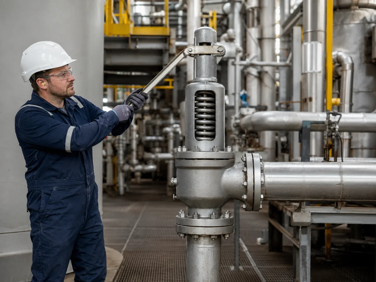
Scena industriale illustrativa; non è una specifica installazione ZOBAI, un registro di prova o un'immagine di certificazione del prodotto.
Partire dall'evidenza: la priorità diagnostica dopo una perdita al test con leva
L'errore principale nella risoluzione dei problemi è passare direttamente da “la valvola perde” a “la taratura della molla è sbagliata”. Quando la perdita inizia immediatamente dopo il sollevamento manuale intenzionale, il primo livello diagnostico dovrebbe rimanere vicino a ciò che è stato fisicamente disturbato: l'interfaccia di tenuta, il gruppo mobile e il meccanismo di sollevamento.
| Priorità | Cosa stabilire | Perché è Importante | Assunzione non sicura da evitare |
|---|---|---|---|
| 1 | Esattamente quando è iniziata la perdita | Conferma se il sintomo è comparso immediatamente dopo il sollevamento manuale. | Presumere che il test abbia modificato permanentemente la pressione di taratura. |
| 2 | Se la leva e il gruppo mobile sono tornati normalmente | Aiuta a individuare attrito, interferenze o riposizionamento incompleto. | Presumere che la posizione esterna della leva dimostri la posizione interna del disco. |
| 3 | Se il fluido di processo può trasportare incrostazioni, solidi o depositi | Aumenta o diminuisce la probabilità di detriti intrappolati sulla sede. | Presumere che azionamenti ripetuti della leva puliscano la sede in modo sicuro. |
| 4 | Se esistono danni noti alla sede o riparazioni precedenti | Una sede marginale può diventare visibilmente permeabile dopo essere stata disturbata. | Presumere che il test con leva abbia causato tutti i danni esistenti. |
| 5 | Se l'evidenza della sede e della meccanica spiega la perdita | In caso contrario, l'indagine può estendersi alle condizioni di processo e di tubazione. | Iniziare con una riprogettazione completa del sistema prima di controllare le parti direttamente disturbate. |
Regola dell'evidenza:
non regolare la molla, modificare la pressione di taratura o specificare una sostituzione finché il sintomo osservato non è stato separato dai requisiti originali di protezione dalla pressione.
non regolare la molla, modificare la pressione di taratura o specificare una sostituzione finché il sintomo osservato non è stato separato dai requisiti originali di protezione dalla pressione.
Cosa cambia all'interno della valvola durante un test con leva di sollevamento?
In una tipica valvola di sicurezza a molla dotata di dispositivo di sollevamento, la leva fornisce un mezzo meccanico per spostare lo stelo e sollevare l'otturatore dalla sede dell'ugello. Il fluido di processo attraversa quindi l'interfaccia di tenuta prima che il gruppo mobile ritorni verso la posizione di chiusura.
Una richiusura affidabile dipende da più del semplice ritorno a riposo della leva visibile. Lo stelo e la guida devono muoversi liberamente, l'otturatore deve tornare verso la posizione di sede prevista e le superfici di tenuta devono essere sufficientemente pulite e non danneggiate per ristabilire un contatto efficace.
Per la sequenza più ampia di forza della molla, sollevamento dell'otturatore e richiusura, vedere
come funziona una valvola di sicurezza a molla.
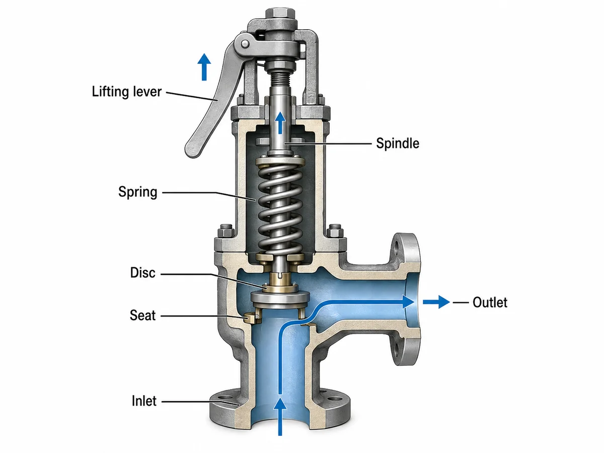
Illustrazione tecnica semplificata. La geometria dei componenti varia in base al progetto della valvola.
Confine ingegneristico:
un dispositivo di sollevamento fornisce solo un controllo funzionale limitato nelle condizioni richieste dal progetto della valvola applicabile, dal codice, dalle istruzioni del produttore e dalla procedura del sito. Il movimento manuale della leva non dimostra la pressione di taratura, l'accettazione della tenuta della sede o la capacità di scarico.
un dispositivo di sollevamento fornisce solo un controllo funzionale limitato nelle condizioni richieste dal progetto della valvola applicabile, dal codice, dalle istruzioni del produttore e dalla procedura del sito. Il movimento manuale della leva non dimostra la pressione di taratura, l'accettazione della tenuta della sede o la capacità di scarico.
Causa 1 — Sporco, incrostazioni o depositi di processo rimangono sulla sede
La contaminazione della sede è una delle prime condizioni da considerare quando si verifica una perdita immediatamente dopo un'operazione di sollevamento manuale. L'apertura della valvola consente al fluido di processo di attraversare l'interfaccia di tenuta che potrebbe essere rimasta chiusa per un periodo prolungato.
Particelle di ruggine, incrostazioni, prodotti di corrosione, solidi o depositi di processo possono muoversi con il fluido. Se la contaminazione rimane tra l'otturatore e l'ugello quando la valvola si chiude, il contatto di tenuta completo potrebbe non essere ripristinato.
La probabilità aumenta quando il servizio può trasportare solidi, prodotti di corrosione, materiale cristallizzante, depositi appiccicosi, materiale polimerizzante o condensa. Il rischio esatto dipende comunque dal design della valvola, dal mezzo, dalla fase, dalla temperatura e dalla condizione di processo.
Scenario ingegneristico composito per formazione
Una valvola di sicurezza a vapore a molla era rimasta ermetica durante il servizio normale. Dopo un controllo programmato di sollevamento manuale, è diventata udibile una piccola perdita continua. Un meccanismo plausibile è che incrostazioni o detriti di corrosione abbiano attraversato l'interfaccia di tenuta e siano rimasti tra l'otturatore e l'ugello durante la chiusura.
Il passo successivo utile è documentare la pressione di esercizio, la condizione di prova e il comportamento della perdita e determinare se è richiesto un controllo ispettivo o un test di tenuta. Modificare la compressione della molla non risolverebbe il problema dei detriti intrappolati.
Causa 2 — Le superfici di tenuta erano già marginali o si sono danneggiate
Non tutte le perdite post-prova derivano da detriti sciolti. Le superfici di tenuta dell'otturatore e dell'ugello possono già presentare corrosione, erosione, graffi, contatto irregolare o danni da manutenzione precedente.
Una valvola può sembrare ermetica prima della prova perché i componenti di tenuta si sono assestati in una particolare posizione di contatto. Una volta che l'otturatore viene sollevato e riportato, lo stesso contatto imperfetto potrebbe non essere ripristinato.
Il test con leva di sollevamento può quindi innescare una perdita visibile senza essere la causa principale originale della condizione della sede.
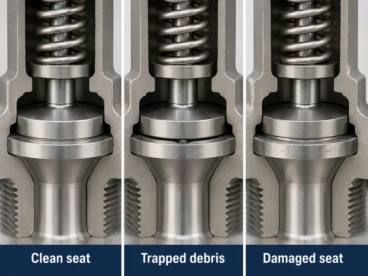
Illustrazione tecnica semplificata per la formazione sulla risoluzione dei problemi.
Quali evidenze supportano una diagnosi di danno alla sede?
Perdita persistente dopo che le condizioni operative si stabilizzano, storia nota di corrosione o erosione, riparazione precedente della sede, danno visibile durante un'ispezione qualificata, o un test di tenuta controllato al di fuori della base di accettazione applicabile possono supportare una diagnosi di condizione della sede.
La sola perdita esterna non è sufficiente per determinare se la riparazione corretta sia pulizia, lappatura, sostituzione del componente o sostituzione completa della valvola. Il metodo di riparazione consentito dipende dal design specifico della valvola, dalla condizione dei componenti, dai requisiti del produttore e dai controlli di riparazione applicabili.
Causa 3 — Il disco, lo stelo o il meccanismo a leva non ritorna liberamente
Le superfici di tenuta possono essere accettabili e la valvola può comunque perdere se il gruppo mobile non riesce a tornare nella posizione di chiusura prevista dopo il sollevamento manuale.
Possibili fattori meccanici
- Contaminazione o corrosione della guida
- Attrito o deformazione dello stelo
- Interferenza meccanica
- Disallineamento
- Montaggio precedente improprio
- Problemi di ritorno del leveraggio di sollevamento
Prove da verificare
- Ritorno anomalo della leva
- Storico di revisione precedente
- Corrosione attorno alle parti mobili
- Bloccaggio rilevato durante ispezione controllata
- Perdite ripetute dopo manutenzione
Il ritorno della leva nella posizione di riposo non dimostra che disco, guida e stelo siano completamente rientrati internamente. Se il movimento è incerto, l'ispezione deve seguire la procedura applicabile del produttore, del sito e di riparazione qualificata.
Per un contesto a livello di prodotto sulle valvole a molla dotate di dispositivo di sollevamento manuale, vedere
valvole di sicurezza a leva.
Scenario ingegneristico composito per formazione
Una valvola inizia a perdere immediatamente dopo un controllo manuale della leva. La leva esterna sembra ritornare normalmente, ma la valvola ha una storia di revisione recente. L'indagine successiva dovrebbe includere l'allineamento della guida, le condizioni dello stelo e la libertà di movimento interna, piuttosto che presumere che la molla si sia indebolita.
Se si conferma un bloccaggio o un disallineamento, l'azione correttiva appartiene a un processo di riparazione qualificata e verifica post-riparazione.
Controllo di escalation secondario — Pressione di esercizio e condizioni di richiusura
Se la contaminazione della sede, il danneggiamento della superficie di tenuta e i problemi di ritorno meccanico non spiegano adeguatamente il sintomo, ampliare l'indagine alla condizione operativa.
Il comportamento della valvola di sicurezza dipende dalla relazione tra pressione di esercizio normale, pressione di taratura, sovrapressione, accumulo, pressione di richiusura e blowdown. Operare troppo vicino alla regione di chiusura stabile della valvola può contribuire a gorgogliamento o perdite continue, ma si tratta di un problema più ampio di condizioni operative piuttosto che di un meccanismo unico del test della leva di sollevamento.
Registrare la pressione di esercizio effettiva e la variabilità del processo prima di trarre conclusioni. Il margine operativo accettabile dipende dal design della valvola, dal fluido, dalla stabilità del servizio, dai dati del produttore, dal codice applicabile e dai requisiti di progetto.
Tenere separati i termini di pressione:
MAWP non è pressione di taratura; sovrapressione e accumulo usano pressioni di riferimento diverse; il blowdown descrive la relazione tra apertura e richiusura; e nessuno di questi valori da solo dimostra la capacità di scarico.
MAWP non è pressione di taratura; sovrapressione e accumulo usano pressioni di riferimento diverse; il blowdown descrive la relazione tra apertura e richiusura; e nessuno di questi valori da solo dimostra la capacità di scarico.
Scenario ingegneristico composito per formazione
La perdita inizia dopo un test manuale della leva, ma poi aumenta e diminuisce con le normali oscillazioni della pressione di processo. Una volta esclusi la contaminazione della sede e il ritorno meccanico, tale comportamento dipendente dalla pressione è un motivo per rivedere il margine operativo e il comportamento di richiusura, piuttosto che attribuire automaticamente il sintomo a un danno permanente della sede.
Controllo di escalation secondario — Installazione, contropressione e tubazioni di scarico
Quando la sede direttamente disturbata e i componenti mobili non spiegano la perdita persistente, esaminare il sistema installato. La perdita di carico in ingresso, la resistenza in uscita, la contropressione, il drenaggio e il carico delle tubazioni possono influenzare il comportamento della valvola e la richiusura, ma si tratta di fattori di sistema generali piuttosto che di cause create specificamente dall'azionamento manuale della leva.
Verifica lato ingresso
- Perdita di pressione in ingresso
- Pulizia delle tubazioni
- Allineamento meccanico
- Modifiche recenti alle tubazioni
Verifica lato uscita
- Contropressione sovrapposta prima dell'apertura
- Contropressione accumulata creata dal flusso di scarico
- Supporto delle tubazioni di scarico
- Drenaggio e sacche di liquido
- Carico meccanico sul corpo della valvola
Vedi la
guida all'installazione delle valvole di sicurezza
per un esame dettagliato di ingresso, uscita, supporto e drenaggio.
Per la distinzione tra pressione di uscita sovrapposta e incorporata e i limiti dei progetti bilanciati, vedere
Contropressione e soffietto.
Perdita immediata vs perdita persistente — cosa può rivelare la tempistica
La tempistica della perdita aiuta a decidere se il primo livello diagnostico debba rimanere concentrato sul disturbo della sede e sul ritorno meccanico o se l'indagine debba essere ampliata. La tempistica è un'evidenza per la prioritizzazione, non una prova della causa principale.
| Osservazione | Prima direzione | Evidenze da raccogliere | Non concludere ancora |
|---|---|---|---|
| La perdita inizia immediatamente dopo il sollevamento manuale | Contaminazione della sede o riassestamento incompleto | Pulizia del servizio, ritorno della leva e tempistica dell'evento | Che la pressione di taratura sia cambiata |
| La perdita rimane continua | Condizione della sede o ritorno meccanico | Test controllato e ispezione qualificata | Che la lappatura sia automaticamente richiesta |
| La perdita varia con la pressione di processo | Passare alla revisione delle condizioni operative | Pressione operativa, pressione di taratura e stabilità del processo | Che la molla sia debole |
| La perdita coincide con variazioni della tubazione o del collettore | Passare alla revisione del sistema installato | Contropressione, supporti, drenaggio e carichi sulle tubazioni | Che il sollevamento manuale abbia causato il problema al sistema |
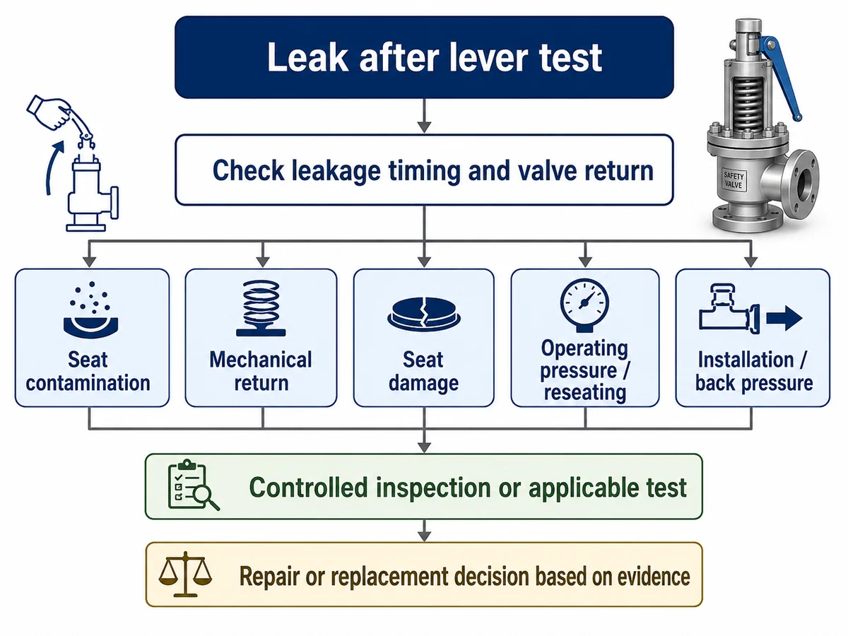
Flusso di lavoro decisionale semplificato. Le fasi di ispezione effettive dipendono dalla valvola, dal processo e dalla procedura applicabile.
Cosa un Test di Sollevamento con Leva Può — e Non Può — Verificare
Un dispositivo di sollevamento è un controllo funzionale limitato nelle condizioni richieste dal progetto della valvola applicabile, dal codice, dalle istruzioni del produttore e dalla procedura del sito. Non deve essere trattato come sostituto di un test controllato di pressione, perdita o capacità.
| Domanda | Può l'Operazione Manuale della Leva Dimostrarlo? | Cosa Serve Invece? |
|---|---|---|
| Il meccanismo di sollevamento pertinente può muoversi? | Solo indicazione funzionale limitata | Procedura di ispezione applicabile e istruzioni del produttore |
| La pressione di taratura effettiva è corretta? | No | Verifica controllata della pressione di taratura |
| La valvola soddisfa un criterio di accettazione della tenuta della sede? | No | Test controllato applicabile della tenuta della sede |
| La capacità di scarico documentata è adeguata? | No | Dati di capacità del produttore o di certificazione in condizioni definite |
| La capacità richiesta è adeguata per lo scenario di scarico determinante? | No | Determinazione del carico di scarico e verifica della capacità |
La capacità di scarico richiesta deve essere stabilita in base allo scenario di scarico determinante e verificata rispetto alla base di capacità documentata o certificata della valvola selezionata. La dimensione dell'attacco dimostra la compatibilità fisica, non la capacità di protezione. L'evidenza della capacità è inoltre specifica per fluido e condizioni: le basi di capacità per vapore, gas, liquido e bifase non devono essere interscambiate senza i dati ingegneristici e del produttore applicabili.
Per la distinzione più ampia sul dimensionamento, vedere
dimensionamento della valvola di sicurezza e alla capacità di sfioro certificata.
Quando diventa necessario il test di tenuta della sede
Una perdita visibile o udibile da una valvola installata è un'osservazione operativa. Un test controllato di tenuta della sede viene eseguito in condizioni definite e risponde a una domanda diversa.
API 527 tratta la tenuta della sede delle valvole di sicurezza dove tale norma fa parte della base di prova applicabile. L'edizione adottata, il design della valvola, il fluido di prova, la pressione, la costruzione della sede e i criteri di accettazione devono comunque essere confermati per il progetto specifico.
Per i dettagli sull'ambito del test di tenuta e l'interpretazione della richiesta di offerta, vedere
Test di tenuta sede API 527.
Non confondere le evidenze:
la tenuta della sede non è capacità di scarico, e un test di pressione di taratura non è un test di capacità.
la tenuta della sede non è capacità di scarico, e un test di pressione di taratura non è un test di capacità.
Cosa non fare dopo che una valvola inizia a perdere
- Non modificare immediatamente la compressione della molla o la regolazione della pressione di taratura.
- Non dare per scontato che l'azionamento ripetuto della leva sia sicuro per ogni valvola e servizio.
- Non ostruire, tappare o isolare in modo improprio il percorso di scarico per fermare una perdita visibile.
- Non dare per scontato che il movimento riuscito della leva dimostri la capacità di scarico.
- Non sostituire la valvola basandosi solo sulla dimensione della connessione.
- Non copiare la pressione di taratura esistente su una valvola di ricambio senza rivedere l'apparecchiatura protetta e la base di progettazione.
- Non eseguire riparazioni interne non controllate su una valvola installata.
Le decisioni di isolamento in sito e di riparazione devono preservare la funzione di protezione dalla pressione richiesta. Una valvola che perde non deve essere semplicemente isolata se ciò rimuove il percorso di scarico richiesto; la procedura approvata dell'impianto e l'autorità tecnica responsabile devono definire la disposizione sicura.
Checklist per la risoluzione dei problemi prima di rimuovere o sostituire la valvola
Prima di scegliere la riparazione o la sostituzione, raccogliere le prove del test con leva e i dati originali di protezione dalla pressione. I dati tecnici mancanti devono rimanere “da confermare” piuttosto che essere dedotti dalla dimensione della connessione o da una targhetta parziale.
Evento del test con leva ed evidenza immediata
- La valvola era a tenuta prima del test?
- Come è stato azionato il dispositivo di sollevamento?
- La perdita è iniziata immediatamente?
- La leva è tornata normalmente?
- Il servizio è sporco, con incrostazioni o formazione di depositi?
- Esiste una storia precedente di sedi o riparazioni?
Dati di protezione e di sistema
- Attrezzatura protetta e scenario di sfioro governativo
- Fluido e fase
- Pressione operativa
- Pressione massima di esercizio (MAWP) o pressione di progetto
- Pressione di taratura
- Capacità di sfioro richiesta e base di calcolo della capacità
- Temperatura di sfioro
- Contropressione sovrapposta e accumulata
- Tubazioni di ingresso e uscita
- Targhetta e registri di manutenzione
- Codice applicabile, edizione adottata e specifica di progetto
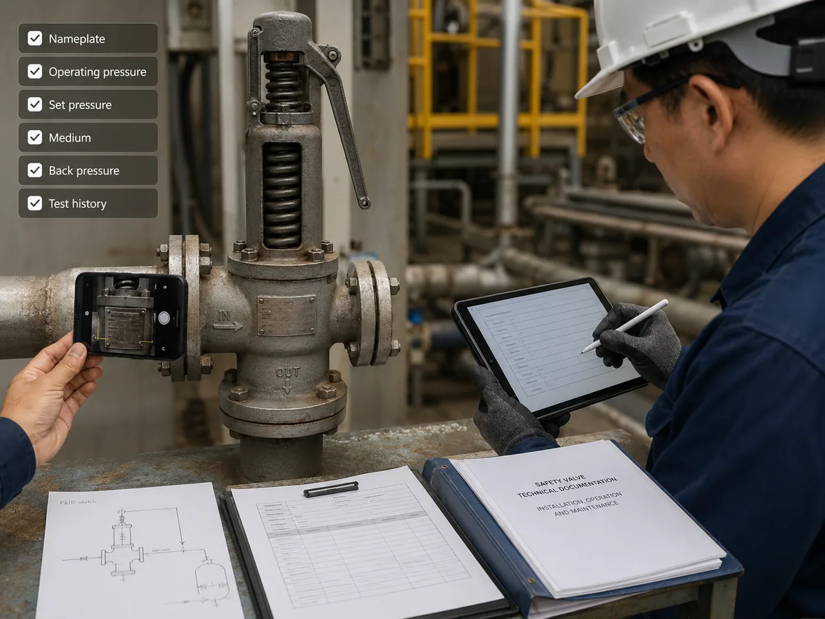
Scena di ispezione illustrativa; i documenti e i valori mostrati non costituiscono prova di un progetto o risultato di test ZOBAI specifico.
Riparare o sostituire? Completare la diagnosi prima di scegliere il rimedio
Per questa specifica modalità di guasto, la riparazione o la sostituzione dovrebbe avvenire solo dopo aver esaminato le cause specifiche della leva. Se si confermano detriti intrappolati, danni alla sede o ritorno meccanico incompleto, la decisione di riparazione può concentrarsi sulle condizioni della valvola interessata. Se questi controlli non spiegano la perdita, è necessario affrontare cause più ampie relative al funzionamento e al sistema installato prima di presumere che la sostituzione della valvola risolva il problema.
| Evidenza | Direzione tecnica | Cosa resta da confermare |
|---|---|---|
| Contaminazione sospetta, nessun danno ai componenti confermato | Percorso di ispezione o pulizia controllata dove consentito | Condizione della sede e prova post-manutenzione richiesta |
| Danno alla sede o all'ugello confermato | Revisione qualificata di riparazione o sostituzione del componente | Limiti di riparazione, identità del componente e verifica finale |
| Bloccaggio della guida, dello stelo o del meccanismo di sollevamento | Riparazione meccanica e verifica post-riparazione | Causa del bloccaggio, corretta assemblaggio e libertà di movimento |
| Nessuna causa specifica della leva spiega la perdita persistente | Passare alla revisione della pressione di esercizio, della contropressione e del sistema installato | Condizioni effettive di processo e di tubazione |
| Condizione della valvola, tracciabilità o riparabilità inaccettabile | Sviluppare una specifica completa per la sostituzione | Base di protezione originale e capacità di sostituzione documentata |
Quando il normale servizio continuativo richiede un intervento
Perdite persistenti, ritorno anomalo della leva o dello stelo, sospetto danneggiamento della sede, cronologia di riparazione incerta, evidenza di grippaggio o impossibilità di verificare la valvola rispetto alla base di protezione richiesta dovrebbero attivare una decisione di ingegneria e ispezione controllata dal sito. L'azione esatta di messa fuori servizio o isolamento dipende dall'apparecchiatura protetta e dai mezzi approvati per mantenere la protezione di pressione richiesta.
I controlli sui materiali di sostituzione fanno parte della revisione della protezione
Non considerare il solo materiale del corpo come prova di idoneità al servizio. Confermare il disco bagnato, l'ugello, la guida, lo stelo e le finiture; l'ambiente della molla; il materiale del soffietto se montato; e la sede o la tenuta rispetto al fluido effettivo, alla fase, alla temperatura di esercizio, alla temperatura di scarico, alla corrosione, all'erosione, allo sporcamento e ai requisiti di progetto.
La dimensione della connessione non equivale alla capacità di scarico.
Una sostituzione deve preservare la base effettiva di protezione dalla pressione, non limitarsi ad adattarsi alle connessioni di ingresso e uscita esistenti.
Una sostituzione deve preservare la base effettiva di protezione dalla pressione, non limitarsi ad adattarsi alle connessioni di ingresso e uscita esistenti.
Sintesi della decisione ingegneristica
- Confermare che la perdita sia iniziata dopo il sollevamento manuale intenzionale.
- Controllare prima l'eventuale contaminazione della sede e le superfici di appoggio danneggiate.
- Controllare le condizioni di ritorno di leva, stelo, guida e disco.
- Utilizzare un'ispezione o una prova controllata quando non è possibile stabilire dall'esterno le condizioni della sede.
- Solo allora, se necessario, ampliare la diagnosi alla pressione di esercizio, alla contropressione e alle condizioni della tubazione.
- Non considerare il funzionamento della leva come prova della pressione di taratura, della tenuta della sede o della capacità.
- Basare la riparazione o la sostituzione su prove concrete e sui requisiti originali di protezione dalla pressione.
- In caso di sostituzione, riconfermare il fluido, la fase, la capacità richiesta, la temperatura di scarico, la contropressione, i materiali, la tubazione e la base normativa/progetto applicabile.
L'obiettivo non è semplicemente fermare la perdita visibile. L'obiettivo è ripristinare la fiducia che il dispositivo di scarico della pressione possa rimanere accettabilmente a tenuta durante il normale funzionamento e fornire comunque la funzione di protezione dalla pressione richiesta quando necessario.
Evidenze tecniche e riferimenti ufficiali
Le seguenti fonti supportano i confini relativi allo scopo delle prove e ai meccanismi di guasto utilizzati in questa sequenza di risoluzione dei problemi. Non dimostrano la certificazione o la conformità di una specifica valvola ZOBAI.
API 527 — Tenuta della sede
L'elenco degli standard pubblicati di API identifica lo Standard API 527, Tenuta della sede delle valvole di sicurezza, come standard per la tenuta della sede. Utilizzare l'edizione adottata dal progetto effettivo, senza presupporre che ogni installazione utilizzi la stessa base di accettazione.
ASME PTC 25 — Prove di prestazione
ASME PTC 25 tratta le prove di prestazione dei dispositivi di scarico della pressione, incluse le prove di capacità di flusso e le prove in servizio o su banco. Tale ambito è diverso dal semplice azionamento manuale della leva di sollevamento.
National Board — Meccanismi di perdita e riparazione
Il materiale tecnico del National Board identifica la presenza di corpi estranei tra sede e disco, una preparazione inadeguata delle superfici di tenuta, problemi allo stelo o alle guide e un montaggio non corretto come meccanismi che possono contribuire a perdite, grippaggio o funzionamento compromesso della valvola.
Limite del codice vigente
L'articolo tecnico del National Board qui citato costituisce una guida ingegneristica storica e non sostituisce il NBIC, il Codice ASME vigente, le istruzioni del produttore o i requisiti giurisdizionali. Verificare i requisiti applicabili alla valvola e all'installazione effettive.
- American Petroleum Institute — Standard pubblicati / API 527
- ASME — PTC 25 Dispositivi di scarico della pressione
- National Board — Riparazioni improprie tipiche delle valvole di sicurezza
Gli standard e i riferimenti tecnici spiegano l'ambito delle prove e i meccanismi ingegneristici; non stabiliscono che ogni modello ZOBAI rechi ogni marchio di codice, certificazione o approvazione di progetto.
Domande Frequenti
Perché la mia valvola di sicurezza ha iniziato a perdere immediatamente dopo un test con la leva di sollevamento?
Il sollevamento manuale separa il disco dalla sua sede. Detriti possono rimanere intrappolati sulle superfici di tenuta, un difetto esistente della sede può diventare evidente, o il gruppo mobile potrebbe non riassestarsi completamente. La causa effettiva dovrebbe essere verificata prima della regolazione.
La sporcizia sulla sede può causare perdite dopo un test con leva di prova?
Sì. Il materiale estraneo tra il disco e la sede può impedire un contatto completo e può contribuire a ulteriori danni alla superficie di tenuta.
La perdita dopo un test con leva significa che la pressione di taratura è cambiata?
No. Una perdita dopo il sollevamento manuale non dimostra di per sé che la pressione di taratura sia cambiata. La verifica della pressione di taratura richiede il test controllato e la procedura appropriati.
Posso azionare di nuovo la leva di sollevamento per fermare la perdita?
Non trattare l'azionamento ripetuto della leva come un metodo di pulizia universale. Se un'altra operazione manuale sia appropriata dipende dal design della valvola, dal fluido di servizio, dalla pressione, dalle istruzioni del produttore, dalla procedura in sito e dal codice applicabile.
Il test della leva di sollevamento dimostra una capacità di scarico sufficiente?
No. Il movimento manuale non dimostra la capacità di scarico richiesta o certificata. La capacità deve essere verificata in base allo scenario di scarico prevalente, al fluido, alle condizioni di scarico, all'orifizio selezionato e ai dati documentati del produttore o della certificazione.
Quando dovrebbe essere testata la tenuta della sede?
Il test controllato della tenuta della sede può essere appropriato quando persistono perdite o quando requisiti di ispezione, riparazione, progetto o codice richiedono una valutazione definita delle perdite. La procedura applicabile e i criteri di accettazione devono essere confermati per la valvola e il progetto.
Quando una valvola di sicurezza che perde deve essere rimossa per ispezione o riparazione?
Perdite persistenti, ritorno meccanico compromesso, sospetto danneggiamento della sede, corrosione, storico di riparazioni incerto o mancato rispetto della base di prova applicabile possono giustificare un'ispezione o una riparazione qualificata.
Limitazioni ingegneristiche e normative
La verifica della leva di sollevamento, la verifica della pressione di taratura, la prova di tenuta della sede e la verifica della capacità di scarico servono a scopi diversi e non devono essere trattate come evidenze intercambiabili.
Le decisioni finali di riparazione o sostituzione dipendono dall'apparecchiatura protetta, dallo scenario di scarico applicabile, dal fluido e dalla fase, dalla pressione di esercizio, dalla MAWP o pressione di progetto, dalla pressione di taratura, dalla capacità di scarico richiesta, dalla temperatura di scarico, dalle contropressioni sovrapposta e accumulata, dalle tubazioni di ingresso e uscita, dai materiali bagnati, dalle condizioni di molla e soffietto ove applicabili, dalla costruzione della sede o della tenuta, dai dati del produttore, dall'edizione della norma applicabile, dalle specifiche di progetto e dai requisiti normativi locali.
Necessità di diagnosticare una perdita dopo una prova con leva?
Inviare l'apparecchiatura protetta, lo scenario di scarico, il fluido e la fase, la pressione di esercizio, la MAWP o pressione di progetto, la pressione di taratura, la capacità richiesta e la base di calcolo se disponibile, la temperatura di scarico, la contropressione, le tubazioni di ingresso/uscita, la targhetta della valvola, le informazioni su materiale e sede se note, la cronologia di manutenzione e una descrizione di quando è iniziata la perdita.