Valve Types & Working Principles What Is a Jacketed Safety Valve? A practical engineering explanation of the separate process-pressure and heating-jacket circuits, what active body heating can and cannot do, and the data required before selection. Two Separate Circuits Working Principle Thermal Boundaries RFQ Data On this pageQuick Answer: What Is a Jacketed Safety Valve?How …

Valve Types & Working Principles
What Is a Jacketed Safety Valve?
A practical engineering explanation of the separate process-pressure and heating-jacket circuits, what active body heating can and cannot do, and the data required before selection.
Quick Answer: What Is a Jacketed Safety Valve?
A jacketed safety valve is a pressure-relief valve with a separate heating-fluid chamber around selected areas of the valve body. Steam, hot water, thermal oil, or another approved heating medium may circulate through that chamber to reduce local heat loss and help the process fluid remain flowable near the nozzle, seat, and body flow path. Jacketed construction may be reviewed when a medium becomes more viscous, crystallizes, waxes, freezes, or solidifies as it cools. The jacket does not create the valve set pressure, establish the required relieving capacity, or guarantee that the inlet branch and discharge piping will remain free of deposits. Final suitability depends on the protected equipment, credible relief scenario, fluid composition and phase, pressure and capacity data, relieving temperature, back pressure, complete thermal path, selected valve design, project specification, and applicable code requirements. The next step is to submit the process-side relief data and the jacket-side utility conditions for preliminary engineering review.
From a pressure-protection perspective, the key concept is simple: a jacketed safety valve contains two different fluid circuits with two different functions. The process side protects the equipment against overpressure. The jacket side provides thermal support. Confusing those circuits can lead to an incomplete specification, an unsuitable replacement, or a valve body that is warm while the actual blockage forms somewhere else in the relief path.
Product-family context should follow the engineering definition, not replace it. Available jacketed configurations and quotation review belong on the confirmed Jacketed Safety Valves product page.
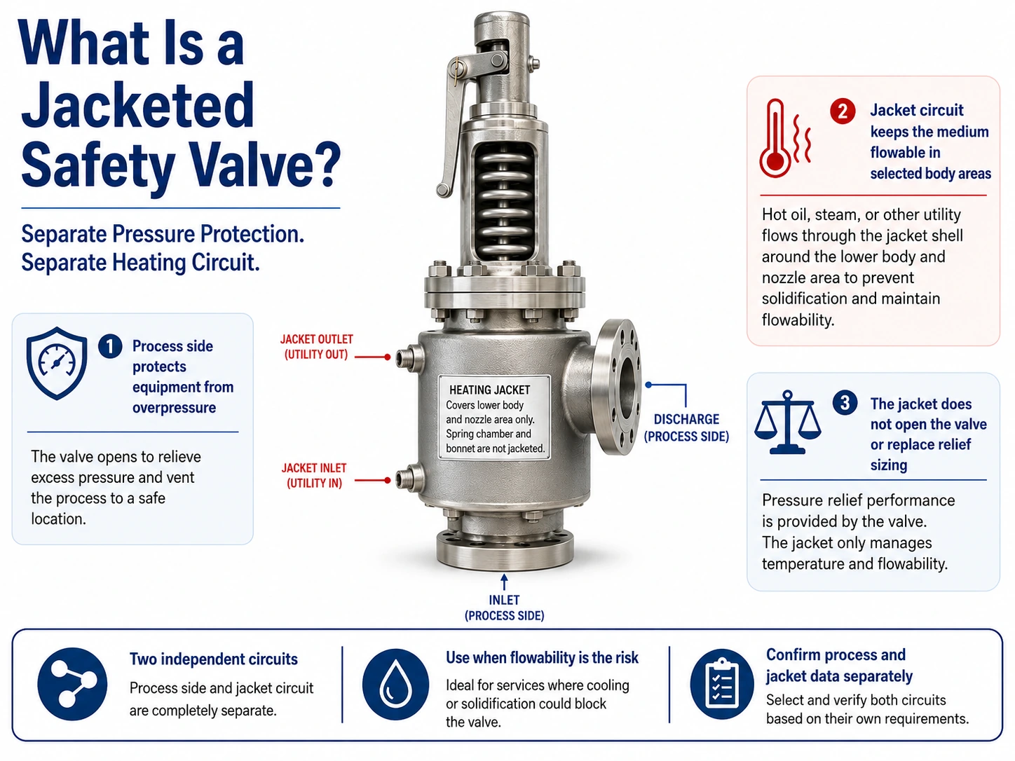
Illustrative engineering graphic, not a certified product drawing. The jacket supports thermal continuity around selected body areas; it does not create set pressure, establish relieving capacity, or heat the complete inlet and outlet system.
How Is a Jacketed Safety Valve Constructed?
A jacketed safety valve usually retains the pressure-relief elements of a conventional spring-loaded design while adding a separate chamber around selected external body regions. Exact construction varies by manufacturer and series. The jacket may cover the inlet body region, the seat/body area, another selected flow-path region, or a larger portion of the pressure-containing body. Jacket coverage must be confirmed from the selected model drawing rather than inferred from the product name.
The two circuits should be shown separately on the datasheet and P&ID:
- the process pressure boundary, which contains the protected process fluid; and
- the heating-jacket circuit, which contains the approved heating medium.
These circuits may be physically close, but they do not perform the same task and must not be specified with one combined set of pressure and temperature data.
The Process Pressure Boundary
The process pressure boundary includes the inlet connection, nozzle, seat, disc, internal body flow path, outlet connection, and other pressure-containing parts in contact with the process medium. The safety valve opens when process pressure acts on the effective disc area and overcomes the closing force established by the valve design.
The detailed pressure, capacity, phase, temperature, back-pressure, piping, material, and document inputs are consolidated later in the process-side selection tables.
The jacket does not change the need for any of these inputs. Connection size alone does not prove orifice size or relieving capacity.
The Separate Heating-Jacket Circuit
The heating jacket is a separate thermal-fluid space. Its purpose is to transfer heat to selected valve-body areas. The heating medium may be steam, hot water, thermal oil, or another project-approved fluid, depending on the selected design and service conditions.
The jacket-side utility data are consolidated later in the jacket-circuit matrix and must be confirmed independently of process pressure and set pressure.
Jacket supply pressure is not the process operating pressure. Jacket design pressure is not the protected equipment MAWP. Neither value is the safety-valve set pressure.
Jacket Inlet, Outlet, Vent, and Drain Connections
The jacket may have supply and return connections, and the selected design may also require a vent, drain, or condensate path. Their arrangement depends on the heating medium, valve geometry, installation orientation, thermal design, and manufacturer instructions.
For steam heating, the project normally needs to address air removal and condensate drainage. For hot water or thermal oil, the project needs a defined circulation path and a method to avoid trapped gas or stagnant zones. A generic drawing should not be treated as a universal connection arrangement.
Final supply, return, vent, drain, and condensate arrangements must follow the selected valve drawing and the approved project piping design.
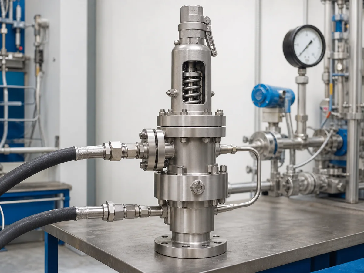
Simplified engineering illustration, not a manufacturing sectional drawing. Process pressure opens the valve; the separate jacket circuit only transfers heat to selected body areas.
How Does a Jacketed Safety Valve Work?
The heating jacket does not replace the valve’s mechanical pressure-relief mechanism. It adds a thermal-control function around selected body areas. The process pressure still opens the valve, and the spring or other closing mechanism still controls reseating behavior.
For a general spring-loaded opening sequence, the reader can refer to How Does a Spring Loaded Safety Valve Work?. The purpose here is to explain what the jacket adds before, during, and after a relieving event.
Standby: Maintaining Thermal Continuity
During normal operation, the safety valve may remain closed for long periods. That standby period can be the most important thermal condition for a viscous, waxy, crystallizing, or solidifying medium. A relatively small body cavity, inlet neck, seat region, or short unheated branch can become a local cold point even when the main process line remains hot.
During standby, the heating medium transfers heat through the jacket wall to selected body areas. Actual temperature depends on circulation, condensate removal, insulation, ambient conditions, geometry, and process-fluid behavior—not supply temperature alone.
Pressure Rise and Opening
When the protected equipment reaches the applicable opening condition, the process fluid acts on the valve’s effective pressure area. The valve opens according to its mechanical design, set pressure, operating margin, overpressure, and service conditions.
The jacket pressure does not assist the opening action. It should remain hydraulically separate from the process flow path. A specification that implies the jacket medium opens the valve confuses thermal support with overpressure protection.
A warm valve body does not prove a clear relief path. Inlet loss, cold reducers, deposits, or outlet back pressure still require separate verification.
Discharge and Reseating
During a relieving event, the process medium passes through the nozzle, seat opening, body, and outlet. The jacket may continue to supply heat where allowed by the operating procedure and selected design. Whether continuous heating is required during relief, startup, shutdown, or maintenance must be defined by the project.
Reseating occurs according to the valve’s mechanical characteristics, pressure behavior, friction, deposits, back pressure, and adjustment limits. Jacket pressure does not set the reseating pressure. If deposits or partial solidification interfere with the disc, guide, seat, or flow path, thermal support alone may not restore correct operation.
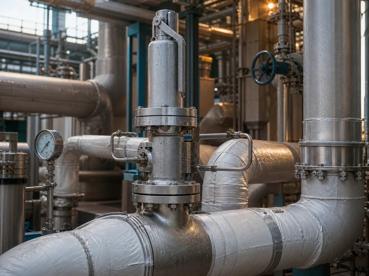
Simplified engineering sequence. Actual opening, lift, blowdown, and reseating depend on the selected valve, service, and applicable test or code basis.
What Does the Heating Jacket Actually Do?
The jacket provides active heat input around selected body areas. Its engineering purpose is not simply to make the valve “hot.” It is to reduce the risk that the process medium loses the flowability required for the valve to remain available as a pressure-relief device.
Reducing Local Cold Spots
A relief path can contain several thermal transitions:
- a heated process vessel or main line;
- a branch connection;
- an inlet reducer;
- the safety-valve nozzle;
- the body and seat region;
- the outlet connection;
- a discharge pipe or header.
A jacketed valve can reduce heat loss from the body region it covers. It cannot automatically eliminate cold points upstream or downstream. The thermal review should therefore identify the full path from the protected equipment to the final discharge location.
The engineering question is not only “Is the valve jacketed?” It is also:
Where can the process medium cool enough to become more viscous, crystallize, wax, freeze, or solidify?
Maintaining Flowability Near the Seat and Body
The seat and adjacent body flow path can be sensitive to deposits. If the medium becomes less flowable near the seat, the valve may experience leakage, delayed movement, incomplete lift, restricted flow, or difficulty reseating. The exact risk depends on the medium, deposit mechanism, valve geometry, standby duration, thermal cycling, surface condition, and maintenance history.
A jacket may help keep the jacketed region closer to the project-defined temperature target. It does not prove that the seat remains clean or that deposits cannot form.
For fluids that react, polymerize, degrade, coke, or become unstable when overheated, more heat is not automatically better. The project must define a safe thermal window and confirm the selected model’s component limits.
Supporting Startup, Standby, and Shutdown Control
Startup, extended standby, batch changeover, shutdown, cleaning, and utility restoration can create the most severe thermal transitions. The operating procedure should define when heating begins, how air or condensate is removed, how thermal shock is limited, and how the relief path remains available throughout the transition.
What Can a Jacketed Safety Valve Not Solve?
Jacketed construction addresses a specific thermal risk. It should not be used to hide missing relief calculations, incorrect piping, unsuitable materials, or an undefined maintenance strategy.
It Does Not Replace Relief Sizing
The jacket does not establish the required relieving capacity. The required rate still comes from the credible relief scenario for the protected equipment. The selected valve must then provide adequate documented or certified capacity for the stated medium, pressure, temperature, and applicable sizing basis.
The following remain separate:
- required relieving rate;
- required effective area;
- selected orifice;
- inlet and outlet connection sizes;
- manufacturer documented or certified capacity.
A larger connection does not automatically mean a larger effective orifice. A jacketed body does not automatically have the same capacity as a visually similar unjacketed valve.
For the complete capacity boundary, use the Safety Valve Sizing and Certified Relieving Capacity Guide and the confirmed API 520 safety valve sizing guide.
It Does Not Correct Piping or Back-Pressure Problems
A jacket does not correct:
- excessive inlet pressure loss;
- an inlet branch that can plug outside the jacketed region;
- liquid pockets;
- unsupported outlet piping;
- thermal expansion loads;
- unsafe discharge direction;
- superimposed back pressure;
- built-up back pressure;
- interaction with a common discharge header.
The inlet and outlet systems remain part of the pressure-relief path. Review them using the Safety Valve Installation Guide and Back Pressure and Bellows.
It Does Not Eliminate Fouling or Material Limits
Heating can reduce some solidification risks, but it cannot eliminate every fouling mechanism. Deposits may result from contamination, corrosion products, chemical reaction, polymerization, coking, erosion, flashing, poor drainage, or particles in the process.
Material grade alone also does not prove suitability. The review should include:
- process-fluid compatibility;
- heating-medium compatibility;
- body and jacket material;
- nozzle, disc, spindle, and guide;
- seat construction;
- spring and spring-chamber exposure;
- gaskets, seals, and packing;
- differential thermal expansion;
- temperature cycling;
- corrosion allowance or surface treatment where applicable.
The selected model and project specification must confirm the complete assembly.
Jacketed Safety Valve vs Insulation vs Heat Tracing
A jacket, insulation, and external heat tracing manage heat in different ways. They may be alternatives in some locations and complementary in others. The correct solution depends on the fluid behavior, required temperature profile, geometry, accessibility, control method, failure consequences, and manufacturer instructions.
| Method | Thermal Function | Typical Coverage | Main Engineering Risk | Confirmation Needed |
|---|---|---|---|---|
| Heating jacket | Adds heat through a circulating fluid around selected body areas | Integrated jacket chamber | Poor circulation, trapped condensate, incorrect supply/return conditions | Selected design, jacket pressure/temperature, flow path, venting and drainage |
| Insulation | Reduces heat loss but does not create heat | External covered surfaces | Blocked vents/drains, hidden leakage, restricted access, trapped moisture | Approved insulation boundary, inspection access and surface-temperature limits |
| External heat tracing | Adds localized heat through tubing or electrical tracing | Selected external surfaces and connecting piping | Incomplete coverage, hot spots, control failure, damage during maintenance | Tracing design, control, power/utility availability and manufacturer approval |
Jacket: Integrated Active Heating
A jacket is an integrated heating-fluid space around selected body areas. It can provide broader local coverage than one tracing line, but coverage, utility conditions, venting, drainage, and operating procedures remain design-specific.
Insulation: Heat-Loss Reduction
Insulation slows heat loss. It does not add energy. In a continuously hot process, suitable insulation may be sufficient to maintain thermal continuity. In a long standby period, insulation may only delay cooling.
Insulation must not cover:
- required bonnet or bellows vents;
- jacket vents or drains;
- nameplates;
- adjustment access;
- inspection points;
- leakage indications;
- moving components;
- surfaces that the manufacturer requires to remain exposed.
External Tracing: Localized External Heating
External tracing can heat inlet branches, reducers, valve surfaces, and outlet piping that a body jacket does not cover. It can therefore be important in a complete thermal system.
However, tracing coverage and control require engineering. A tracing line located far from the coldest region may provide little benefit. Electrical tracing may require temperature controls and hazardous-area review. Steam tracing requires condensate management. The method must remain compatible with the selected valve and maintenance access.
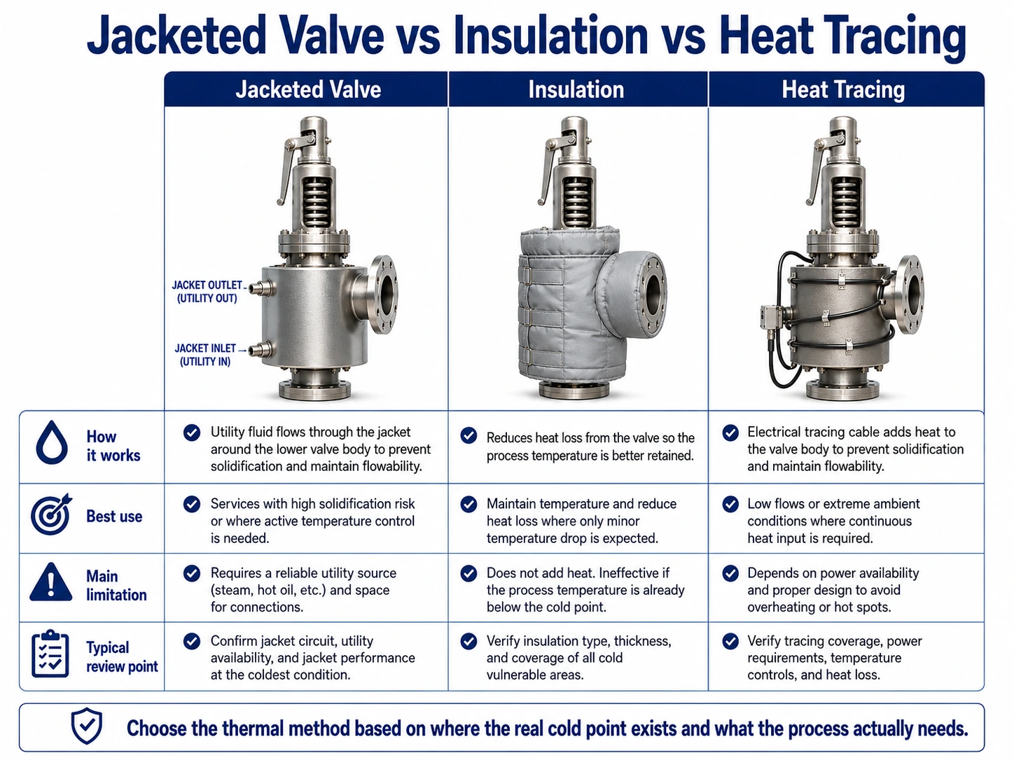
Simplified engineering comparison. Jacket, insulation, and tracing may be used separately or together only where the selected design and project approve the arrangement.
Jacketed Safety Valve vs High-Temperature Safety Valve
These terms describe different engineering concerns.
A high-temperature safety valve is selected so that the pressure-containing parts, trim, seat, spring, bonnet, gaskets, seals, bellows or pilot components, and connections remain suitable at the governing temperatures.
A jacketed safety valve adds active heating around selected body areas to help maintain process-fluid flowability.
High-Temperature Compatibility
High-temperature review focuses on:
- relieving temperature;
- body and flange pressure-temperature ratings;
- trim and seat materials;
- spring-chamber temperature;
- gasket and seal limits;
- oxidation, corrosion, galling, and thermal cycling;
- selected-model temperature limits.
A hot dry gas may require high-temperature-compatible components but no jacket if the gas does not become viscous or solidify during heat loss.
For product-family context, refer to High Temperature Safety Valves.
Active Flowability Control
Jacketed construction focuses on keeping a process medium flowable around selected body areas. The absolute temperature may be moderate compared with another process, yet the fluid may crystallize, wax, or become highly viscous after a small temperature drop.
The decision therefore depends on fluid behavior, not on a universal “high-temperature” threshold.
When Both Reviews Are Required
Some services may require both:
- components suitable for the governing process and relieving temperatures; and
- active heating to reduce flowability loss during standby or discharge.
In that case, the project must confirm both the process-side temperature limits and the jacket-side heating conditions. A jacket does not increase the allowable temperature of a spring, gasket, seal, bellows, or pilot component unless the selected design specifically supports that condition.
When May Jacketed Construction Be Appropriate?
Jacketed construction may deserve further review when the process medium can lose the flowability needed for reliable pressure relief. The screening decision should be based on actual fluid behavior and the complete thermal path.
Further review is justified when the medium can lose flowability in the valve-body region during standby or thermal cycling. The evidence should identify the fluid’s temperature-dependent behavior, the actual cold point, the complete inlet-to-discharge thermal path, utility reliability, safe heating window, and whether insulation or tracing can control the risk. A jacket may be unnecessary for a hot dry gas, a medium that remains flowable at the lowest credible temperature, or a service where heating creates degradation, polymerization, or coking risk.
Preliminary Jacketed-Service Decision Matrix
Use this matrix as a screening tool, not as a final product-selection rule. A jacket is justified only when the thermal problem, coverage, operating procedure, and pressure-relief duty are all defined.
| Observed Condition | Preliminary Direction | Required Evidence | Stop Condition |
|---|---|---|---|
| The medium remains flowable at the lowest credible temperature in the complete relief path. | A jacket may be unnecessary; review insulation or tracing only where heat loss still matters. | Fluid property data, minimum credible temperature, standby duration, and complete thermal-path review. | Do not add a jacket only because the service is described as “hot” or “viscous.” |
| The medium becomes highly viscous, waxy, crystalline, frozen, or solid in the valve-body region during standby. | Review jacketed construction together with inlet/outlet thermal continuity. | Viscosity or phase-behavior data, cold-point location, heat-loss assessment, and jacket coverage drawing. | Do not proceed if the actual cold point is outside the jacketed region and remains uncontrolled. |
| The process branch or outlet is the dominant cold point. | Prioritize approved tracing, insulation, drainage, or piping changes; a body jacket alone may be incomplete. | Branch geometry, reducer layout, outlet routing, tracing plan, insulation boundary, and drainage. | Do not treat a warm valve body as proof that the complete relief path is available. |
| Heating may degrade, polymerize, coke, or react with the process medium. | A jacket may be unsuitable or require a tightly controlled thermal window. | Safe temperature range, reaction/degradation data, component temperatures, and operating safeguards. | Do not increase utility temperature or pressure without a verified thermal and material basis. |
| The jacket utility is unreliable or cannot be safely vented, drained, isolated, and monitored. | Resolve the utility and operating philosophy before relying on jacketed construction. | Utility availability, supply/return design, vent/drain concept, failure response, and maintenance access. | Do not specify a jacket as a critical safeguard without a credible operating and maintenance plan. |
How Should the Heating Medium, Vent, and Drain Be Reviewed?
The jacket is an operating pressure and temperature circuit. It should have a defined design basis rather than an informal utility connection.
Treat the jacket as an independent pressure and thermal circuit. Confirm the heating medium, supply and return conditions, jacket design limits, circulation method, venting, drainage or condensate removal, expansion, isolation, startup, shutdown, and failure response. Connection orientation is model- and project-dependent; a generic top-in/bottom-out rule is not sufficient.
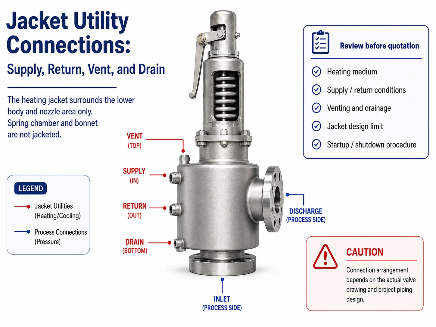
Simplified engineering illustration. Actual supply, return, vent, drain, trap, and connection orientation must follow the selected valve drawing and project piping design.
Jacket-Circuit Design Data Matrix
The jacket should be reviewed as an independent pressure and thermal circuit. The selected design must confirm each item below before the utility connection is treated as complete.
| Jacket-Side Item | What Must Be Confirmed | Failure Risk if Missing | Required Evidence |
|---|---|---|---|
| Heating medium | Identity, cleanliness, compatibility, phase, and whether the selected design permits it. | Corrosion, fouling, poor heat transfer, or an unsuitable utility conversion. | Project utility specification and selected-manufacturer confirmation. |
| Supply condition | Supply pressure, temperature, available differential pressure, and control method. | Insufficient heating, overheating, thermal shock, or exceeding jacket limits. | Utility datasheet, control philosophy, and jacket design limits. |
| Return condition | Expected return pressure/temperature, restriction, and discharge or recovery destination. | Stagnant flow, trapped condensate, pressure build-up, or unstable heat transfer. | Return-system P&ID and hydraulic/thermal review. |
| Vent | High-point gas or air removal where required by the selected orientation and medium. | Air binding, incomplete filling, reduced heated area, or unstable circulation. | Selected valve drawing and project vent arrangement. |
| Drain / condensate path | Low-point drainage, condensate removal, trap or return concept, and safe isolation. | Flooded jacket, uneven heating, corrosion, freeze risk, or thermal cycling. | Piping drawing, trap/return basis, and operating procedure. |
| Expansion and isolation | Thermal expansion allowance, isolation sequence, pressure relief of trapped utility, and maintenance state. | Connection loads, gasket leakage, trapped-pressure hazard, or damage during startup/shutdown. | P&ID, piping flexibility review, and lockout/isolation procedure. |
What Process-Side Data Still Control Safety-Valve Selection?
The jacket-side specification is only one part of the valve datasheet. The process side still controls the pressure-protection duty.
The process side still controls the protection duty. Confirm the protected equipment and relief scenario, medium and phase, operating pressure, MAWP or design pressure, set pressure, required relieving rate, relieving pressure and temperature, inlet loss, superimposed and built-up back pressure, outlet system, materials, and required documents. Valve type and nominal connection size do not replace these inputs.
For relief-scenario, flare, vent, and depressuring-system context, use the API 521 pressure relief systems guide.
Required Capacity vs Selected Valve Data
Jacketed construction changes the thermal configuration; it does not remove the need to reconcile the required relief duty with the selected valve’s documented capacity and pressure limits.
| Term | Engineering Meaning | Why It Must Stay Separate | Verification Source |
|---|---|---|---|
| Required relieving rate | The mass or volumetric rate derived from the governing credible relief scenario. | It is a process requirement, not a property of the jacket or nominal valve connection. | Relief calculation and scenario basis. |
| Required effective area | The calculated minimum flow area for the stated medium and relieving conditions. | It is not the same as the inlet flange bore or jacket coverage. | Applicable sizing method and project calculation. |
| Selected orifice | The manufacturer’s actual flow-area designation for the chosen valve design. | A nominally similar jacketed and unjacketed body may not have identical internal geometry. | Selected-manufacturer datasheet or drawing. |
| Inlet / outlet connection size | The piping-interface dimensions. | Connection size does not prove orifice size, capacity, or replacement equivalence. | Outline drawing and piping specification. |
| Documented or certified capacity | The capacity basis accepted for the selected valve, medium, and applicable requirements. | A jacket does not automatically increase capacity or preserve another model’s rating. | Manufacturer capacity data and required certification/test documents. |
| Jacket coverage | The body region receiving active heating. | Thermal coverage does not prove pressure capacity or complete relief-path availability. | Sectional/outline drawing and thermal review. |
Back-Pressure Decision Table
Back pressure remains a separate design input. The jacket does not balance outlet pressure or make a conventional valve insensitive to a variable discharge system.
| Back-Pressure Condition | Question to Answer | Potential Effect | Required Action |
|---|---|---|---|
| Constant superimposed back pressure | What pressure exists at the outlet before the valve opens, and is it included in the selected design basis? | Can affect opening behavior, cold differential test pressure, and allowable operating margin. | Confirm the selected construction and manufacturer procedure for the stated condition. |
| Variable superimposed back pressure | How does outlet pressure vary before opening and over the operating cycle? | May change opening/reseating behavior and support review of balanced or another approved construction. | Provide the full range and variability; do not use one average value. |
| Built-up back pressure | What pressure develops during the required relieving flow through the outlet system? | Can reduce capacity, affect stability, increase reaction loads, and alter discharge performance. | Calculate the discharge system at the governing flow and selected outlet configuration. |
| Common header interaction | Can another relieving device or process source pressurize the shared header? | May combine superimposed and built-up effects and create time-dependent outlet pressure. | Review simultaneous scenarios, header hydraulics, and the selected valve limits. |
| Blocked, fouled, or cold outlet | Can deposits, condensate, or solidification restrict the discharge path? | May create unquantified back pressure and prevent safe discharge. | Treat as a piping/thermal availability problem; a jacketed body alone is not corrective action. |
Medium and Material Screening Matrix
Material screening should cover all wetted and temperature-sensitive parts in both fluid circuits, including the body, jacket shell, nozzle, disc, guide, spindle, spring, bellows where fitted, seat or seal, gasket, packing, bolting, and external utility connections. A body alloy alone does not establish complete assembly suitability.
| Screening Area | Process-Side Question | Jacket-Side Question | Decision Boundary |
|---|---|---|---|
| Body and jacket shell | Is the pressure-containing body compatible with the process medium and relieving temperature? | Is the jacket shell compatible with the utility and jacket design condition? | Both boundaries must be confirmed independently. |
| Nozzle, disc, spindle, and guide | Can deposits, corrosion, galling, or thermal expansion affect movement and seating? | Can heat conduction change clearances or component temperature? | Confirm complete trim and movement-system limits, not only body material. |
| Seat, gasket, seal, and packing | Are leakage, chemical compatibility, and relieving-temperature limits acceptable? | Can utility heat or cycling exceed the material’s allowable condition? | Soft or metal seat selection is model- and service-specific. |
| Spring / spring chamber | What temperature reaches the spring during standby and relieving conditions? | Can jacket heat or insulation raise the spring-chamber temperature? | Use selected-model temperature data and required correction procedures. |
| Deposits and fluid stability | Does the medium crystallize, polymerize, coke, or degrade within the proposed thermal window? | Can the heating medium create local overheating or an uncontrolled temperature gradient? | More heat is not automatically safer or more reliable. |
| Bolting and external connections | Are process flange, bolting, and gasket ratings suitable at the governing condition? | Are jacket connections and bolting suitable for utility pressure, temperature, cycling, and loads? | Process and utility connection ratings must not be inferred from one another. |
What Can Go Wrong in Jacketed Service?
A jacketed valve can still be unavailable or unreliable if the thermal circuit, process path, or maintenance strategy is incomplete.
| Symptom or Risk | Possible Cause | First Engineering Check | Do Not Assume |
|---|---|---|---|
| Valve body cools during standby | No heating flow, blocked return, trapped gas or condensate, excessive heat loss | Supply, return, vent, drain, utility condition and insulation | The process valve mechanism is defective |
| Repeated process-side plugging | Cold inlet branch, unheated reducer, seat deposits, outlet cold point | Complete thermal path from equipment to discharge | The body jacket heats every location |
| Jacket pressure becomes unstable | Blocked return, thermal expansion, incorrect isolation | Jacket P&ID, relief/expansion provisions and operating procedure | Process set pressure is affected in the same way |
| External leakage | Jacket connection, process connection, gasket or thermal-cycling issue | Identify which circuit is leaking and isolate safely | A cross-circuit leak exists without inspection |
| Set-pressure or reseating concern | Deposits, guide friction, spring exposure, back pressure or calibration issue | Test history, process deposits, spring chamber and piping conditions | Jacket pressure sets the valve |
| Components overheat | Excessive utility condition, insulation boundary, heat conduction | Actual component temperatures and selected-model limits | More heating always improves reliability |
Common failure paths include loss of heating flow, trapped condensate or gas, blocked return, cold inlet or outlet sections outside the jacket, deposits at the nozzle or seat, thermal shock, gasket leakage, and overheating of temperature-sensitive components. Troubleshooting must separate the jacket utility, the complete process flow path, and the pressure-relief mechanism.
Installation and Operating Do / Do Not Matrix
| Do | Do Not | Engineering Reason |
|---|---|---|
| Support the outlet piping independently and review thermal expansion and reaction loads. | Use the safety-valve body or outlet flange as the pipe support. | External loads can distort the valve, affect alignment, and damage connections. |
| Keep jacket vents, drains, nameplates, leakage indications, and inspection access visible. | Cover required openings and access points with permanent insulation. | Blocked or hidden points can defeat venting, drainage, inspection, or fault detection. |
| Define the complete inlet-to-discharge thermal path. | Assume a jacketed body heats the inlet branch, reducer, outlet, or common header. | The dominant cold point may remain outside the jacketed region. |
| Introduce the heating medium under a controlled startup procedure. | Apply maximum utility condition to accelerate warm-up without checking component and fluid limits. | Thermal shock, overheating, gasket leakage, or process degradation may result. |
| Identify the process circuit before isolating or opening the jacket circuit. | Assume an external leak belongs to one circuit without safe identification. | Process and utility leakage require different isolation and hazard controls. |
| Use the selected-manufacturer drawing for supply, return, vent, and drain orientation. | Copy a generic connection arrangement to every model and installation. | Jacket geometry and operating medium determine the required arrangement. |
Troubleshooting Decision Flow
When performance changes, separate the thermal circuit, the process flow path, and the pressure-relief mechanism before assigning a cause.
- Confirm the protected equipment remains covered — Verify that the valve is in service, the inlet path is open, and no isolation arrangement has defeated the required relief path.
- Check jacket utility availability — Record actual supply and return pressure/temperature, venting, drainage, condensate removal, and flow—not only the utility setpoint.
- Locate the cold point or deposit — Inspect the inlet branch, reducer, nozzle/seat region, body, outlet, and discharge header rather than assuming the jacketed body is the only risk area.
- Separate pressure-relief causes — Review operating margin, set-pressure history, inlet loss, superimposed/built-up back pressure, deposits, and spring/guide exposure.
- Use qualified inspection and test evidence — Do not adjust set pressure or disassemble the valve from symptoms alone; follow the selected manufacturer and project procedure.
Composite Engineering Examples: Where a Jacket Helps—and Where It Does Not
The following are composite engineering scenarios for training. They are not customer projects, verified field results, or evidence that a specific ZOBAI model is suitable.
Scenario A: Viscous Heated Liquid with Standby Heat Loss
A jacket may help the body and seat region, but only when viscosity-temperature data, standby duration, required capacity, relieving temperature, and the inlet/outlet thermal path show that the jacketed region is the relevant cold point.
Scenario B: Crystallizing Chemical with Condensate-Control Risk
Steam heating may be considered, but the decision still depends on the safe process temperature range, jacket design conditions, venting, condensate removal, return arrangement, materials, capacity, and back pressure.
Scenario C: Hot Dry Gas That Does Not Solidify
The primary review may be temperature rating, trim, spring-chamber exposure, discharge piping, reaction force, and back pressure. A jacket may add complexity without solving a flowability risk.
Minimum RFQ Data for a Jacketed Safety Valve
A useful RFQ separates process-side and jacket-side information.
| Data Group | Minimum Information | Why It Matters |
|---|---|---|
| Protected equipment and scenario | Equipment tag, protected boundary, credible overpressure case, P&ID | Defines the pressure-protection duty |
| Process medium | Composition, phase, viscosity-temperature behavior, crystallization or solidification information | Defines flowability, sizing and material risks |
| Process pressure | Operating pressure, design pressure/MAWP, set pressure, allowed overpressure basis | Prevents pressure terms from being confused |
| Process capacity | Required relieving rate, calculation basis, relieving pressure and temperature | Defines required area and selected capacity |
| Back pressure and piping | Superimposed/built-up back pressure, inlet/outlet connections, branch layout, tracing, insulation, support and drainage | Supports stability, capacity and thermal-path review |
| Jacket conditions | Heating medium, supply/return pressure and temperature, flow path, jacket design conditions | Defines the thermal circuit |
| Jacket vent and drain | Vent, drain, condensate handling, trap/return concept, isolation | Supports effective heat transfer and safe operation |
| Materials | Body, jacket, trim, seat, spring, gasket, seals and bolting | Confirms compatibility with both circuits |
| Documents | Datasheet, drawings, material records, test requirements, capacity basis and inspection documents | Defines acceptance evidence |
| Replacement evidence | Existing nameplate, model, datasheet, installation photos, test and maintenance history | Prevents replacement by appearance or size alone |
A complete RFQ must provide both the process protection basis and the jacket utility basis. For replacement work, include the existing nameplate, original datasheet, connection drawing, jacket coverage, installation photographs, test history, and every known deviation.
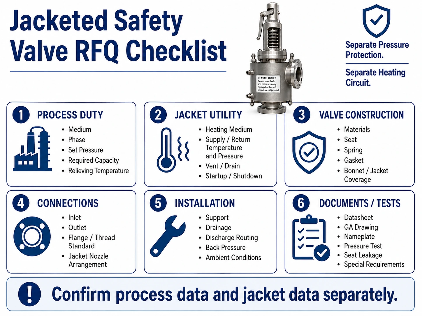
Simplified engineering checklist. Final RFQ fields depend on the selected valve, relief scenario, project specification, required documents, and applicable standards.
Test and Document Matrix
The purchase order should identify which evidence is required, who reviews it, and whether it applies to the process valve, the jacket circuit, or the complete ordered assembly.
| Evidence Item | What It Supports | What It Does Not Prove Alone | RFQ / Review Action |
|---|---|---|---|
| Relief calculation | Required relieving rate, scenario, pressure, temperature, and sizing basis. | That a particular valve model has sufficient accepted capacity. | Provide the calculation and reconcile it with the selected valve data. |
| Manufacturer capacity data / required certification | Selected-orifice capacity for the stated medium and conditions within the accepted basis. | That inlet loss, back pressure, or piping are acceptable. | Specify the required evidence and applicable edition/jurisdiction. |
| Set-pressure test record | Recorded opening/set-pressure performance under the stated test procedure. | Hot-service behavior, complete installation suitability, or zero leakage. | State test medium, pressure basis, acceptance criteria, and documentation requirement. |
| Seat-tightness test record | Leakage performance under the stated test method and condition. | Leakage under every process medium, temperature, deposit, or back-pressure condition. | Define the required test method, medium, pressure, and acceptance basis. |
| Material records | Traceability of the specified pressure-containing or ordered materials. | Complete chemical compatibility or suitability of all trim, seat, gasket, spring, and jacket parts. | Identify which components require records and any supplementary examination. |
| Jacket pressure / leak test evidence | Integrity of the separate jacket circuit under the specified test basis. | Process-side pressure capacity or thermal performance in service. | Specify jacket test pressure/basis through the approved project/manufacturer procedure. |
| Outline / sectional drawing | Connections, dimensions, jacket coverage, vent/drain location, and installation interfaces. | Actual thermal duty or suitability for an unspecified medium. | Approve the drawing against the P&ID, piping, insulation, support, and access requirements. |
| Installation and maintenance instructions | Required orientation, handling, inspection, operating, and maintenance boundaries. | Project compliance without implementation and qualified work. | Include the current selected-model instructions in the document package. |
Replacement Verification Workflow
A replacement should reproduce the required protection function, not merely the appearance, nominal size, or presence of a jacket.
- Recover the original protection basis — Identify the protected equipment, governing relief scenario, required rate, set pressure, relieving temperature, and back-pressure condition.
- Capture the existing valve evidence — Record the complete nameplate, model, orifice, materials, jacket connections, drawings, test history, and installation photographs.
- Check process-side equivalence — Compare selected orifice, accepted capacity, pressure-temperature rating, trim, seat, spring, and inlet/outlet interfaces.
- Check jacket-side equivalence — Compare heating medium, jacket coverage, supply/return/vent/drain arrangement, jacket limits, utility connections, and thermal procedure.
- Review installation effects — Recheck inlet loss, outlet back pressure, support, drainage, thermal expansion, insulation, tracing, and maintenance access.
- Document deviations and approval — List every difference and obtain the required engineering, manufacturer, owner, and jurisdictional acceptance before service.
Technical References
Use the adopted project edition and confirm scope, jurisdiction, and acceptance criteria. These links support the engineering framework but do not prove that a specific ZOBAI valve is certified for a particular service.
- API 520 Part IOfficial API page for API 520 Part I, 10th Edition. Use the edition adopted by the project for sizing and selection.
- API Standard 521Official API page for pressure-relieving and depressuring systems. The page does not state an edition; verify the project’s adopted edition separately.
- ASME BPVC Section XIIIOfficial ASME page for BPVC Section XIII, 2025, covering rules for overpressure protection. Applicability depends on the adopted code and jurisdiction.
- ISO 4126-1Official ISO 4126-1:2013 page. ISO reports the edition was reviewed and confirmed in 2025 and remains current; it is a product standard, not an application standard.
- National Board Temperature ConsiderationsNational Board guidance supporting manufacturer-specific temperature limits and consideration of temperature effects on valve operation and capacity.
Frequently Asked Questions
01What is the purpose of a jacket on a safety valve?
The jacket provides active heating around selected valve-body areas. Its purpose is to reduce local heat loss and help a viscous, waxy, crystallizing, freezing, or solidifying process medium remain flowable near the relief path. It does not replace sizing or guarantee that the complete inlet and outlet system will remain clear.
02Does the heating jacket change the safety valve set pressure?
No. The safety-valve set pressure belongs to the process pressure-relief mechanism. Jacket supply pressure is a separate utility condition and must remain within the selected jacket design limits. Any temperature-related test correction must follow the selected manufacturer’s documented procedure and project requirements.
03Can steam, hot water, and thermal oil all be used in the jacket?
They may be considered only where the selected jacket design and project approve the heating medium, pressure, temperature, materials, circulation, venting, drainage, and operating procedure. A valve configured for one heating medium should not be assumed suitable for another.
04Is a jacketed safety valve the same as an insulated safety valve?
No. Insulation reduces heat loss but does not create heat. A jacket contains a circulating heating medium that adds heat around selected body areas. Some systems use both, subject to the approved insulation boundary and access requirements.
05Does every high-temperature safety valve need a jacket?
No. High-temperature selection concerns the temperature capability of the pressure-containing and internal components. A jacket is considered when active heating is needed to maintain process-fluid flowability. A hot dry gas may require high-temperature-compatible materials without needing a jacket.
06Can the jacket prevent all plugging or crystallization?
No. It may reduce the risk in the jacketed region, but plugging can still occur in the inlet branch, reducer, nozzle, seat, outlet, dead legs, or discharge header. Fluid behavior, complete thermal coverage, cleaning, piping, and operating procedures must also be reviewed.
07What data are required before selecting a jacketed safety valve?
Provide the protected equipment, relief scenario, medium and phase, operating pressure and temperature, design pressure or MAWP, set pressure, required relieving capacity and basis, relieving temperature, back pressure, inlet and outlet piping, heating medium, jacket supply and return conditions, vent/drain requirements, materials, applicable standards, tests, drawings, and document requirements.
Send Your Process and Jacket Conditions for Engineering Review
Before quotation, provide two complete data sets.
Process side:
- protected equipment and relief scenario;
- process medium, composition, and phase;
- viscosity, crystallization, waxing, freezing, or solidification behavior;
- operating pressure and temperature;
- design pressure or MAWP;
- set pressure;
- required relieving capacity and calculation basis;
- relieving pressure and temperature;
- superimposed and built-up back pressure;
- inlet and outlet piping;
- materials;
- applicable standard and document requirements.
Jacket side:
- heating-medium type;
- supply pressure and temperature;
- return pressure and temperature;
- circulation or condensate arrangement;
- jacket design pressure and temperature;
- supply, return, vent, and drain connections;
- isolation, startup, shutdown, and maintenance requirements;
- insulation boundary.
Use Ask an Engineer for preliminary engineering review or Contact ZOBAI to submit an RFQ and available project documents.
Final selection remains subject to the actual relief calculation, selected-manufacturer data, project specification, applicable standard edition, jurisdictional requirements, and project approval.