Share your medium, set pressure, temperature, size, standard, or datasheet, and our team will review your requirement and respond with the appropriate next step.
Quick Answer: How a Bellows Balanced Safety Valve Works A bellows balanced safety valve works by using a flexible metallic bellows to reduce the influence of outlet back pressure on the valve disc, spring chamber and moving parts. In a conventional spring loaded safety valve, outlet pressure can act on internal surfaces and change the …
Quick Answer: How a Bellows Balanced Safety Valve Works
A bellows balanced safety valve works by using a flexible metallic bellows to reduce the influence of outlet back pressure on the valve disc, spring chamber and moving parts. In a conventional spring loaded safety valve, outlet pressure can act on internal surfaces and change the effective opening force. In a bellows balanced design, the bellows isolates the bonnet and spring chamber from process fluid and outlet pressure. Its effective area is selected to offset part of the back pressure force acting on the disc assembly, so set pressure, opening behavior and reseating performance are less affected by variable discharge pressure. This does not mean back pressure can be ignored. The discharge system, certified relieving capacity, inlet pressure loss, bellows material, bonnet vent treatment and inspection method still need to be reviewed for each project.
Engineering summary: the bellows is not only a sealing part. It is part of the valve’s pressure balance, corrosion isolation and reliability strategy. For project selection, a bellows balanced safety valve should still be checked against back pressure conditions, certified relieving capacity, inlet pressure loss, material compatibility, bonnet vent treatment and inspection requirements. If the bellows is damaged, plugged, incorrectly vented or made from unsuitable material, the valve may lose its intended back pressure compensation and the spring chamber may become exposed to process fluid.
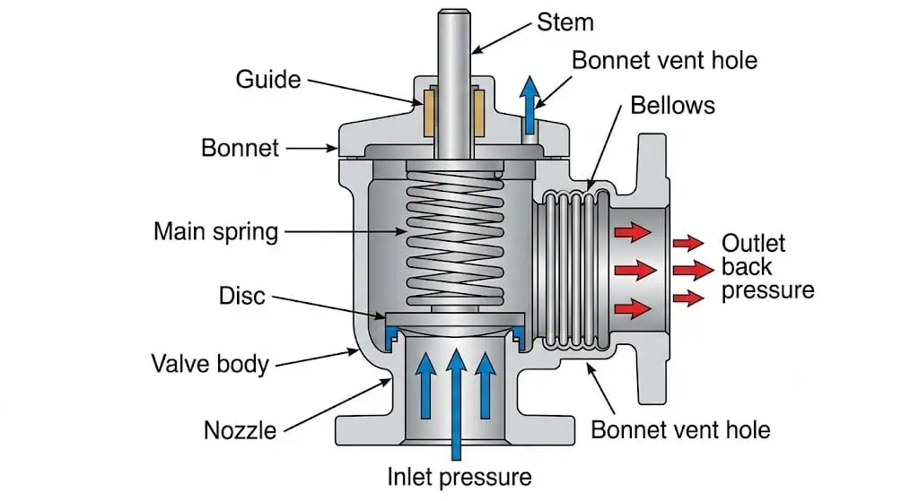
Bellows balanced safety valve cutaway showing the bellows, spring chamber, disc, nozzle, bonnet vent, inlet and outlet flow path.
What Is a Bellows Balanced Safety Valve?
A Practical Definition for Pressure Relief Systems
A bellows balanced safety valve is a spring loaded pressure relief valve designed to reduce the effect of back pressure on valve operation. It uses a metallic bellows between the process side and the bonnet or spring chamber. The bellows helps isolate the spring chamber from outlet pressure and process fluid while allowing the disc assembly to move during opening and closing.
For engineers, the word “balanced” should not be understood as “back pressure no longer matters.” It means the valve structure is designed to reduce back pressure influence compared with a conventional spring loaded safety valve. The discharge system, back pressure level, outlet piping resistance, set pressure, required relieving capacity, inlet pressure loss and valve construction still need to be checked together. For a broader decision process, see ZOBAI’s safety valve selection guide.
Terminology should also be controlled in the purchase specification. In many projects, the terms safety valve, relief valve, safety relief valve, PSV and SRV are used differently depending on fluid service, code basis and local practice. A bellows balanced design describes the valve construction, but it does not replace the need to confirm whether the valve is being purchased as a safety valve, safety relief valve or pressure relief valve under the applicable project requirement.
How It Differs from a Conventional Spring Loaded Safety Valve
A conventional spring loaded safety valve uses spring force to keep the disc closed until inlet pressure reaches set pressure. If back pressure develops on the outlet side, it can change the force balance across the disc and affect opening pressure, lift, capacity and reseating behavior. This is especially important when the valve discharges into a common header, flare system or closed discharge piping.
A bellows balanced safety valve adds a bellows to compensate for part of this back pressure effect. It can also protect internal moving parts such as the spring, guide and stem from corrosive or dirty process fluid. This makes it useful in many chemical, petrochemical and refinery services where conventional valves may be limited by variable back pressure or corrosive discharge conditions.
Why a Bellows Is Added to the Valve Structure
The bellows is added for two main reasons. First, it helps balance the force caused by outlet back pressure so that changes in discharge pressure have less influence on the set pressure and valve stability. Second, it forms a flexible barrier between process fluid and the spring chamber. This can reduce corrosion, fouling and sticking of spring chamber components.
Why this matters: if a conventional valve is used where variable back pressure is significant, the valve may open late, chatter, lose capacity or reseat unpredictably. If corrosive fluid reaches the spring chamber, the spring, guide, stem or adjusting components may corrode or stick. Both situations can increase maintenance cost, shorten service life and reduce protection reliability.
How Does a Bellows Balanced Safety Valve Work?
Step 1: Inlet Pressure Acts Under the Disc
During normal operation, process pressure acts under the valve disc through the nozzle. The spring applies a downward force that keeps the disc seated. As long as the inlet pressure remains below set pressure, the valve should remain closed and tight within the specified seat tightness expectation.
Why it matters: set pressure determines when the valve starts to relieve pressure. If normal operating pressure is too close to set pressure, or if the seat has been damaged by previous chatter, the valve may leak during normal operation. Seat leakage affects product loss, emissions control, maintenance frequency and operating cost.
Step 2: Spring Force Keeps the Valve Closed Before Set Pressure
The spring is adjusted so that the valve starts to open at the required set pressure under the specified test condition. In real operation, temperature, back pressure, installation condition and service medium can influence performance. For this reason, set pressure should not be checked separately from the actual system conditions.
Overpressure and accumulation should also be understood correctly. Overpressure is the pressure increase above set pressure during a relieving event, while accumulation relates to the pressure increase above the protected equipment’s allowable pressure basis. A valve can have the correct set pressure but still fail the protection objective if certified relieving capacity, inlet loss or outlet back pressure has not been reviewed.
Step 3: Outlet Back Pressure Acts on the Discharge Side
Back pressure is pressure existing at the outlet of a pressure relief valve. It may be superimposed back pressure, which exists before the valve opens, or built-up back pressure, which develops as a result of flow through the discharge system during relieving. Both can influence valve behavior if not properly accounted for. For services where outlet pressure is a major selection driver, see ZOBAI’s high back pressure safety valve application page.
In a conventional safety valve, outlet back pressure can act on the disc holder and other internal areas. This may change the net force required to lift the disc. The result can be incorrect opening behavior, reduced lift, unstable discharge or poor reseating.
Step 4: The Bellows Balances the Back Pressure Force
In a bellows balanced design, the bellows is arranged so that its effective area helps offset the force created by back pressure on the disc assembly. The design target is to reduce the influence of outlet pressure on the opening force. This is why balanced bellows valves are often selected when back pressure is variable or when a valve discharges into a closed outlet system.
The bellows does not increase the required relieving capacity by itself. Capacity still depends on the required relieving load, orifice area, certified capacity basis, fluid state, inlet pressure loss and discharge system conditions. In procurement review, connection size should never be treated as proof of capacity. This should be checked against safety valve sizing and certified relieving capacity, not only inlet and outlet flange size.
Step 5: The Valve Opens and Relieves Excess Pressure
When inlet pressure reaches set pressure, the disc lifts from the seat and the valve begins to relieve excess pressure. As flow increases through the valve and discharge piping, built-up back pressure may develop. The balanced bellows helps reduce the effect of this back pressure on valve movement, but the discharge system must still be checked for acceptable pressure loss and stability.
A common field problem occurs after several relief devices are connected to a common discharge header during a plant upgrade. The individual valve set pressure may remain correct, but the header pressure during simultaneous relief can increase. If this condition is not included in the sizing review, the valve may chatter, lose effective relieving capacity or reseat unstably. The corrective action is to review superimposed back pressure, built-up back pressure, simultaneous relief assumptions and the discharge header resistance before approving the valve selection. For related outlet system checks, refer to ZOBAI’s back pressure and bellows engineering guide.
Step 6: Pressure Drops and the Valve Reseats
After the overpressure condition is relieved, system pressure falls and the spring force pushes the disc back toward the seat. Reseating stability depends on spring force, blowdown behavior, flow stability, back pressure, seat condition and discharge piping. If back pressure remains high or fluctuates rapidly, reseating can become unstable even when the valve is balanced.
Blowdown affects the pressure range between opening and reseating. If blowdown behavior is not suitable for the system, the valve may cycle, chatter or remain open longer than expected. This affects seat life, noise, discharge piping stress and maintenance planning.
Step
Pressure Condition
Bellows Function
Disc / Spring Behavior
Engineering Result
Normal operation
Inlet pressure below set pressure
Isolates spring chamber from process fluid
Spring keeps disc closed
Valve remains seated if seat, spring setting and operating margin are correct
Back pressure exists
Outlet pressure is present before or during relieving
Reduces back pressure effect on disc force
Opening force is less affected than in a conventional valve
Set pressure and stability are better protected, within design limits
Opening
Inlet pressure reaches set pressure
Moves with disc assembly
Disc lifts against spring force
Valve begins to relieve excess pressure
Relieving
Flow creates built-up back pressure
Maintains balanced effect
Disc lift depends on sizing and flow conditions
Certified capacity and discharge system must support required relief load
Reseating
System pressure falls
Continues isolating bonnet area
Spring returns disc to seat
Stable reseating reduces leakage, vibration and seat damage
Force balance in a bellows balanced safety valve: inlet pressure, spring force, outlet back pressure and bellows effective area all affect opening and reseating behavior.
How the Bellows Reduces the Effect of Back Pressure
Effective Bellows Area and Nozzle Seat Area
The pressure balance of a bellows balanced safety valve depends on effective areas. Back pressure creates force on internal surfaces. The bellows effective area is selected so that the back pressure force acting on the disc assembly is compensated to a practical extent. This allows the valve to behave more consistently when outlet pressure changes.
For selection work, the exact allowable back pressure influence should be confirmed with the valve manufacturer and the applicable standard or project specification. The term “balanced” should not be treated as permission to ignore outlet pressure, discharge piping, inlet pressure loss or certified relieving capacity.
Superimposed Back Pressure vs Built-Up Back Pressure
Superimposed back pressure exists at the outlet before the valve opens. It may be constant or variable. Built-up back pressure is generated by flow through the valve and discharge piping after the valve opens. Both must be considered because they can affect opening, lift, capacity and reseating behavior.
Back Pressure Item
Why It Matters
Data Needed for Review
Superimposed back pressure
Can affect set pressure and opening force
Constant or variable outlet pressure before relief
Built-up back pressure
Can affect lift, capacity and reseating
Outlet pressure during the relieving event
Common discharge header
May create variable pressure during simultaneous relief
Header design, connected valves and relief scenarios
Flare or closed discharge system
May impose system pressure on valve outlet
Flare header pressure and hydraulic calculation basis
Valve design limit
Determines whether bellows design is acceptable
Manufacturer data and project specification
Why Conventional Safety Valves Are More Sensitive to Back Pressure
A conventional spring loaded safety valve has no bellows barrier to isolate the bonnet and disc holder area from outlet pressure. When back pressure changes, the net force acting on the disc can change. This may shift opening behavior or reduce stability, especially in closed discharge systems.
What “Balanced” Means in Real Valve Selection
In real selection, “balanced” means reduced sensitivity, not unlimited tolerance. Engineers still need to confirm the back pressure type, back pressure magnitude, relieving capacity, outlet piping arrangement and service medium. If back pressure is very high, highly variable or combined with complex two-phase relief, a detailed engineering review is required before selecting the valve. The early screening should follow a structured safety valve selection workflow.
What the Bellows Protects Inside the Valve
Protecting the Spring Chamber from Process Fluid
The bellows forms a flexible barrier between the process side and the bonnet or spring chamber. This can prevent corrosive, toxic, dirty or sticky fluid from reaching the spring and upper guiding components. In services where process fluid could damage spring chamber parts, this isolation function may be as important as the back pressure balancing function.
Reducing Corrosion on the Spring, Guide and Stem
Corrosion in the spring chamber can change spring behavior, increase friction, cause guide sticking or create unpredictable valve movement. If the valve is used in acidic, chloride-containing, sour, wet or corrosive service, material review should cover not only the body and nozzle but also the bellows, stem, guide, spring, gaskets and exposed trim parts.
In one typical review case, a valve body material was selected for a corrosive process, but the internal moving parts and bellows material were not reviewed with the same care. After service exposure, corrosion products increased friction around the guide and affected repeatable reseating. The corrective action was to reassess wetted and exposed parts as a complete material system, not only the pressure-retaining body. The prevention is to specify body, trim, bellows, spring chamber and gasket materials together during procurement review. For related applications, see ZOBAI’s corrosive service safety valve page.
Isolating Moving Parts from Dirty or Corrosive Media
Dirty media can deposit solids on guides, stems and disc holders. Corrosive vapor can attack exposed spring chamber components. The bellows helps isolate these areas, but the bellows itself is a thin-wall flexible component. It must be compatible with temperature, corrosion, vibration and mechanical movement.
Why Bellows Material Compatibility Matters
Bellows failure is different from ordinary gasket leakage. A damaged bellows may allow process fluid to enter the bonnet and may also remove the intended back pressure compensation. This can change the valve’s operating assumption. For this reason, bellows material selection, inspection interval and leakage detection method should be part of the valve review.
Why the Bonnet Vent Hole Must Be Reviewed
The Bonnet Space Must Stay at the Correct Reference Pressure
In many balanced bellows designs, the bonnet space above the bellows must be vented to a defined reference pressure, commonly atmosphere or a safe vent route depending on the service. This allows the bellows to perform its balancing function. If the bonnet vent is plugged incorrectly, pressure can build in the bonnet and change the force balance.
Vent Hole as a Bellows Leakage Detection Point
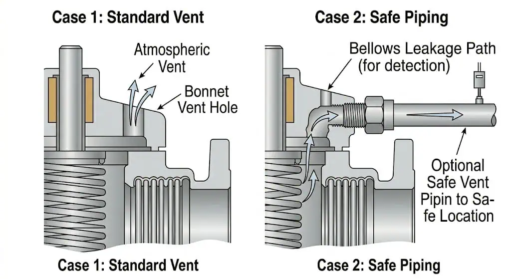
The bonnet vent can also help indicate bellows leakage. If process fluid appears at the vent, it may suggest bellows damage or leakage through the pressure boundary of the bellows. This is why vent treatment should be defined in the installation and maintenance plan, especially for toxic, flammable or corrosive fluids.
What Can Go Wrong If the Vent Is Plugged
One field mistake is treating the bonnet vent as an unwanted leak path and plugging it during installation. This can defeat the balancing function and may cause late opening, unstable lift or incorrect reseating. The correct action is to check the manufacturer’s instructions and project requirements before any vent connection is plugged, piped or routed to a safe location.
When Vent Piping or Safe Discharge May Be Required
If the process fluid is toxic, flammable or environmentally restricted, the vent may need to be piped to a safe location. The vent piping should not create pressure build-up that prevents the bellows from working as designed. This is a small installation detail with a direct effect on valve safety and maintainability.
The bonnet vent hole helps maintain the correct reference pressure above the bellows and may also indicate bellows leakage. It should not be plugged without engineering review.
Bellows Balanced vs Conventional Safety Valve
Back Pressure Sensitivity
A conventional valve is simpler and may be suitable for clean services with low or stable back pressure. A bellows balanced valve is usually considered when back pressure is variable, when a closed discharge system is used or when conventional valve performance may be affected by outlet pressure.
Corrosive or Dirty Fluid Exposure
In corrosive or dirty services, a conventional valve may expose spring chamber parts to process fluid. A bellows balanced valve can reduce this exposure, but the bellows must be compatible with the medium and service temperature.
Maintenance Complexity and Cost
A bellows balanced valve has more components than a conventional spring loaded valve. The bellows can fatigue, crack or corrode. Inspection and maintenance should include bellows condition, vent leakage, guide movement, seat condition and spring chamber cleanliness. Initial cost may be higher, but incorrect valve selection can cost more through leakage, instability, downtime and repeated maintenance.
When a Conventional Safety Valve Is Still the Better Choice
A conventional safety valve may still be the better choice for clean, non-corrosive services with low back pressure and easy maintenance access. Using a bellows balanced design where it is not needed can add cost and maintenance complexity without improving protection.
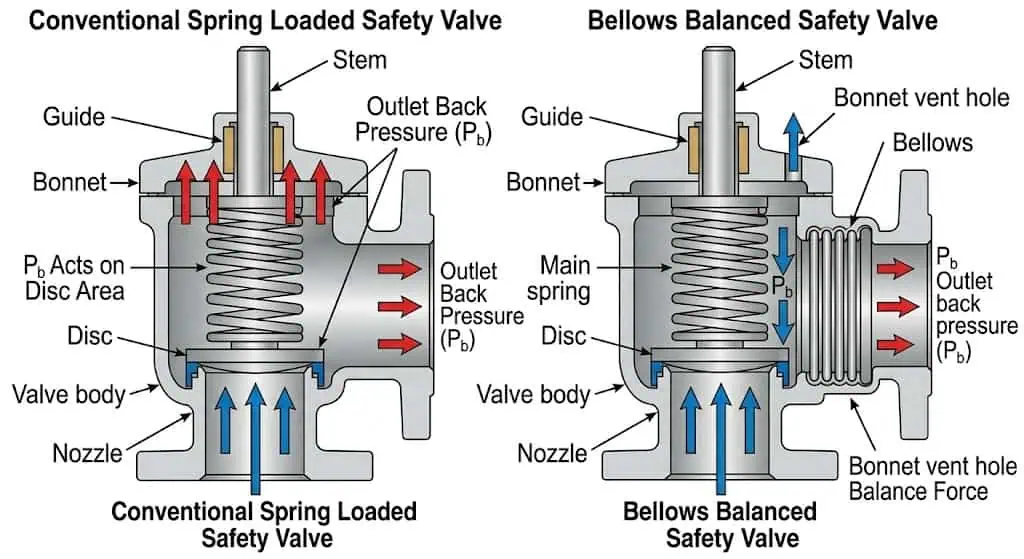
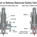
Comparison between a conventional safety valve and a bellows balanced safety valve. The bellows design helps reduce back pressure influence and isolate the spring chamber from process fluid.
Selection Factor
Conventional Safety Valve
Bellows Balanced Safety Valve
Engineering Note
Back pressure
More sensitive to outlet pressure
Designed to reduce back pressure influence
Back pressure still requires calculation and review
Corrosive service
Spring chamber may be exposed depending on design
Bellows can isolate spring chamber
Bellows material must be compatible with the medium
Maintenance
Simpler structure
Additional bellows inspection required
Consider lifecycle cost, not only initial price
Closed discharge system
May be limited by back pressure
Often more suitable, within design limits
Confirm outlet pressure and discharge header behavior
Failure risk
Fewer flexible sealing components
Bellows fatigue or rupture must be considered
Inspection and vent monitoring are important
Bellows Balanced vs Pilot Operated Safety Valve
Two Different Ways to Handle Back Pressure
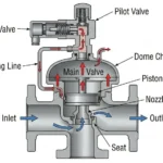
A bellows balanced valve is still a spring loaded safety valve. It uses a bellows to reduce back pressure influence and isolate the spring chamber. A pilot operated safety valve uses a pilot valve and dome pressure to control the main valve. Both may be considered in back pressure applications, but they solve the problem in different ways.
Clean Gas Service vs Dirty or Corrosive Service
Pilot operated valves can be effective in selected high-pressure, clean gas or vapor services, especially where tight shutoff near set pressure is required. However, pilot passages can be sensitive to contamination. Bellows balanced valves may be more practical in some corrosive or dirty services, provided the bellows material and maintenance requirements are acceptable.
Maintenance and Inspection Differences
Bellows balanced valves require inspection of bellows condition, vent leakage and spring chamber protection. Pilot operated valves require inspection of pilot passages, sensing lines, dome seals and main valve response. Selection should be based on service conditions, maintenance capability and the applicable code basis.
How to Decide Between Bellows Balanced and Pilot Operated Designs
The decision should consider medium cleanliness, back pressure type, required capacity, operating pressure margin, temperature, corrosion, maintenance access, documentation requirements and procurement lead time. Neither design is automatically better. The correct choice depends on the full pressure relief system.
Where Bellows Balanced Safety Valves Are Commonly Used
Chemical and Petrochemical Plants
Chemical and petrochemical systems often involve corrosive media, closed discharge piping, flare headers or variable outlet pressure. Bellows balanced valves may be considered when both back pressure compensation and spring chamber protection are required. For corrosive or dirty process media, review ZOBAI’s corrosive service safety valve application information.
Common Discharge Headers and Flare Systems
When multiple relief devices discharge into a common header or flare system, outlet pressure can vary during relief events. A bellows balanced valve may reduce the effect of this pressure on valve operation, but the flare or header system still needs to be reviewed as part of the pressure relief design.
Corrosive, Toxic or Expensive Process Fluids
For corrosive or toxic fluids, isolating the spring chamber can reduce damage and exposure risk. For expensive process fluids, stable reseating and seat tightness can also affect operating cost. The vent path must be reviewed carefully if the fluid cannot be released safely to atmosphere.
Closed Discharge Systems with Variable Outlet Pressure
Closed discharge systems can create superimposed or built-up back pressure. A bellows balanced valve may be selected to reduce sensitivity to these conditions. However, excessive back pressure beyond the design assumptions can still reduce stability or capacity.
Services Where Spring Chamber Protection Is Needed
Services with corrosive vapor, sticky deposits, polymerizing fluids or wet corrosive gases may require spring chamber protection. The bellows can help, but the bellows itself must be reviewed for corrosion, fatigue and temperature limitations.
Engineering Limits and Failure Risks You Should Not Ignore
Bellows Fatigue, Rupture or Mechanical Damage
The bellows is a flexible component that moves with the valve. Repeated cycling, vibration, corrosion or mechanical damage can lead to fatigue or rupture. If the bellows fails, the valve may lose its balancing function and process fluid may enter the bonnet area.
A typical warning sign is process fluid, vapor or residue appearing at the bonnet vent. The immediate issue may look like a simple leakage problem, but the real concern is that the bellows may no longer isolate the bonnet or provide the intended back pressure compensation. The corrective action is to remove the valve from service according to plant procedure, inspect the bellows and internal parts, retest the valve and review material compatibility. The prevention is to include vent monitoring, bellows condition and service cycle history in the maintenance plan.
Corrosion and Cracking of Thin-Wall Bellows Elements
Because the bellows is thin and flexible, it may be more sensitive to corrosion or cracking than the valve body. For sour service, chloride-containing streams or aggressive chemicals, material review should include bellows metallurgy, trim, welds and exposed components.
Plugged Bonnet Vent or Incorrect Vent Piping
An incorrectly plugged bonnet vent can change the pressure reference above the bellows. Incorrect vent piping can also create restriction or pressure build-up. Both can defeat the intended balancing effect and complicate leak detection.
Excessive Back Pressure Beyond Design Limits
A bellows balanced valve has practical design limits. If back pressure is outside the acceptable range, or if the discharge system creates unstable pressure pulsation, the valve may not perform as expected. In such cases, outlet piping design, valve type and relief scenario should be reviewed together.
Wrong Bellows Material for Medium or Temperature
Material mismatch can lead to corrosion, loss of flexibility, cracking or leakage. The bellows material should be reviewed separately from the body material because the bellows sees movement, thin-wall stress and chemical exposure.
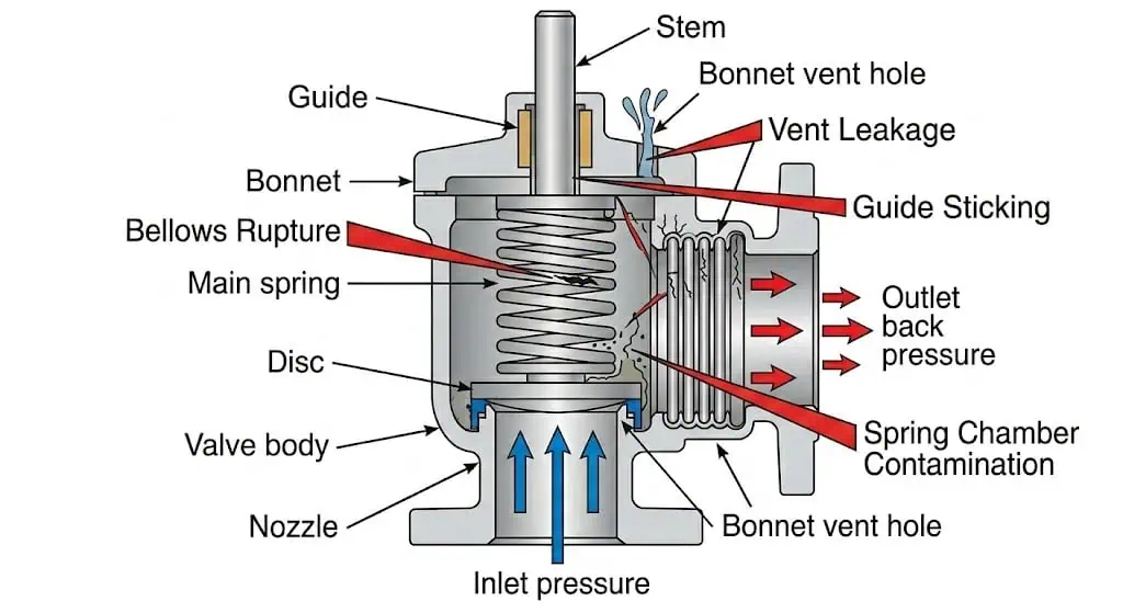
Common failure locations in a bellows balanced safety valve include bellows rupture, corrosion cracking, vent leakage, guide sticking and seat leakage.
Failure Mode
Possible Cause
Field Symptom
Engineering Risk
Prevention
Bellows rupture
Fatigue, corrosion, vibration or mechanical damage
Fluid at bonnet vent or abnormal valve behavior
Loss of back pressure compensation and possible bonnet contamination
Inspect bellows, review material and monitor vent leakage
Vent plugged
Incorrect installation or misunderstanding of vent function
Late opening, unstable lift or incorrect reseating
Balanced function may be defeated
Follow manufacturer instruction and project installation requirements
Corroded internal parts
Wrong material or bellows leakage
Sticking, leakage or poor repeatability
Maintenance cost and reduced reliability
Review body, trim, bellows, spring and guide materials
Chatter
Oversizing, inlet pressure loss or unstable discharge pressure
Rapid opening and closing
Seat damage and piping stress
Check sizing, inlet piping, outlet piping and back pressure
Seat leakage
Seat damage, contamination or unstable operation
Continuous leakage after reseating
Product loss and maintenance work
Specify seat tightness requirement and inspect after relief events
How to Select a Bellows Balanced Safety Valve
Process Data Required Before Sizing or Selection
Selection should start with the pressure relief scenario, not with connection size. The required relieving capacity, fluid state, set pressure, allowable overpressure, operating temperature and discharge system must be reviewed before selecting the valve type. For general project screening, use ZOBAI’s safety valve selection guide together with the service-specific data in this article.
Back Pressure Data Required for Engineering Review
The manufacturer or engineering team needs to know whether back pressure is constant or variable, whether it is superimposed or built-up, and whether the valve discharges to atmosphere, a closed header or a flare system. Without this data, the word “balanced” does not provide enough information for safe selection.
Medium, Temperature and Material Compatibility Checks
Medium compatibility should include body, nozzle, disc, guide, spring, bellows, gaskets and vent piping. Temperature can affect spring setting, bellows fatigue life, seal selection and material strength. If the service contains H₂S, chlorides, acids or other corrosive components, material review should be documented.
Capacity, Orifice Area and Certified Relieving Capacity
A bellows balanced safety valve must still be sized for the required relieving load. The orifice area and certified capacity basis are more important than the visible flange size. A valve with matching inlet and outlet connections may still be unsuitable if the capacity, back pressure or fluid state is not correct.
One common replacement mistake is selecting a new valve only by matching the old flange size, pressure class and set pressure. If the protected equipment duty has changed after process expansion, the old certified capacity may no longer be sufficient. The correct action is to recheck the relief scenario, required capacity, orifice area, inlet pressure loss and outlet back pressure before purchase. For capacity review, refer to the safety valve sizing and certified relieving capacity guide.
Installation and Maintenance Access Requirements
Installation review should include inlet line pressure loss, outlet piping support, discharge reaction forces, bonnet vent treatment, drainage, access for inspection and whether the valve can be removed for testing. Maintenance access affects downtime and lifecycle cost. For more installation details, see ZOBAI’s safety valve installation guide.
When to Ask the Manufacturer for Engineering Review
Engineering review is recommended when the service involves variable back pressure, corrosive fluid, toxic fluid, high temperature, closed discharge piping, two-phase flow, frequent cycling, unusual installation or special documentation requirements.
Medium name and composition
Gas, vapor, steam, liquid or two-phase service
Operating pressure and set pressure
Required relieving capacity
Superimposed back pressure
Built-up back pressure during relief
Operating and relieving temperature
Body and trim material requirement
Bellows material requirement
Soft seat or metal seat requirement
Inlet and outlet size
Flange standard and pressure class
Discharge system or flare header data
Bonnet vent treatment
Required test documents
Applicable code or project specification
Project review CTA: If you are selecting a bellows balanced safety valve for a pressure vessel, chemical process line, flare header or corrosive service, send ZOBAI your medium, set pressure, required relieving capacity, back pressure data, temperature, material requirement and discharge system information. These details allow an engineering review of whether a bellows balanced valve, conventional valve or pilot operated valve is more suitable for your application.
Testing, Inspection and Maintenance Considerations
Set Pressure Test
The set pressure test confirms the pressure at which the valve starts to open under specified test conditions. If cold differential test pressure, temperature correction or back pressure correction is applicable, the test basis should be documented before the valve is released.
Seat Tightness Test
Seat tightness testing checks leakage when the valve is closed. This matters for emissions, product loss, environmental control and maintenance planning. If the project requires tighter leakage limits than the usual standard basis, this should be specified in the purchase order.
Bellows Integrity and Vent Leakage Check
The bellows should be checked for damage, leakage or abnormal deformation where the inspection method allows. The bonnet vent should be reviewed for signs of process fluid, blockage or incorrect piping. Vent leakage may indicate bellows damage and should not be ignored.
Visual Inspection of Bellows, Stem, Guide and Nozzle
Inspection should include the bellows, stem, guide, nozzle, disc, seating surface, spring chamber and vent area. Corrosion, deposits, galling, deformation or mechanical damage can affect repeatability and reseating.
Documentation Required After Repair or Recalibration
After repair or recalibration, documentation may include set pressure test report, seat tightness record, material certificate, inspection report, repair record, nameplate confirmation and sealing record. If local jurisdiction or project specification requires authorized repair, the repair route should be confirmed before work begins.
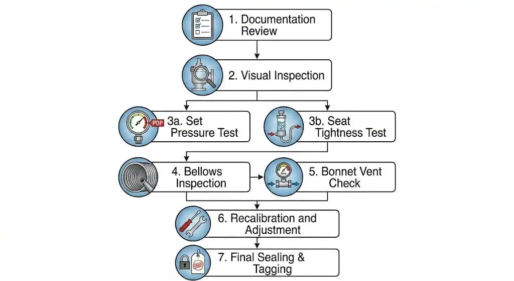
After maintenance, the valve should not be returned to service based only on visual condition. Set pressure, seat tightness, bellows condition, vent condition, sealing and documentation should be checked according to the applicable plant procedure, project specification and local jurisdictional requirement. Where a National Board VR repair route is required, the repair organization and documentation scope should be confirmed before work is released.
Testing and inspection workflow for bellows balanced safety valves, including set pressure testing, seat tightness testing, bellows inspection, bonnet vent check, documentation review and sealing.
FAQs About Bellows Balanced Safety Valves
What is a bellows balanced safety valve?
A bellows balanced safety valve is a spring loaded safety valve that uses a metallic bellows to reduce the effect of outlet back pressure and isolate the spring chamber from process fluid.
How does a bellows balanced safety valve work?
It works by using the bellows effective area to help offset back pressure forces acting on the disc assembly. This reduces the influence of outlet pressure on set pressure, opening behavior and reseating performance.
Why is a bellows used in a safety valve?
The bellows is used to reduce back pressure influence and protect bonnet or spring chamber components from corrosive, dirty or toxic process fluid.
Does a bellows balanced safety valve eliminate all back pressure problems?
No. It reduces back pressure influence within the design limits, but outlet piping, discharge header pressure, certified capacity and valve stability must still be reviewed.
What happens if the bellows fails?
If the bellows fails, the valve may lose its intended back pressure compensation and process fluid may enter the bonnet area. Vent leakage or abnormal operation may indicate bellows damage.
Should the bonnet vent hole be open or plugged?
The bonnet vent treatment should follow the manufacturer’s instructions and project requirements. In many balanced bellows designs, the bonnet space must be vented properly. Incorrect plugging can affect valve operation.
When should you use a bellows balanced safety valve?
It is commonly considered when back pressure is variable, when the valve discharges into a closed system, or when spring chamber components need protection from corrosive or dirty fluids.
What is the difference between bellows balanced and pilot operated safety valves?
A bellows balanced valve remains a spring loaded valve and uses a bellows for back pressure compensation. A pilot operated valve uses a pilot and dome pressure to control a main valve. The correct choice depends on medium, pressure, back pressure, capacity and maintenance conditions.
What information is needed to select a bellows balanced safety valve?
Key information includes medium, fluid state, set pressure, operating pressure, required relieving capacity, superimposed and built-up back pressure, temperature, material requirement, connection standard and discharge system details.
Why is certified relieving capacity more important than connection size?
Connection size only tells you how the valve connects to the piping. It does not confirm whether the valve can pass the required relieving load. The orifice area, certified capacity basis, fluid state, inlet pressure loss and outlet back pressure must be reviewed before selection.
Standards and Technical References Note
Final valve sizing, selection, installation and testing should be verified according to the applicable project code, local regulation and manufacturer data. For bellows balanced safety valve applications, engineers commonly review API 520 Part I for sizing and selection, API 520 Part II for installation, API 521 for pressure-relieving and depressuring systems, API 527 for seat tightness testing, ISO 4126-1 for safety valve general requirements, ASME Boiler and Pressure Vessel Code requirements where applicable, National Board Inspection Code requirements where jurisdictionally required, National Board VR repair requirements where repair authorization applies, and manufacturer technical manuals. Specific editions, certification scope and project applicability must be verified before publishing or procurement.
Publishing note: do not state compliance with ASME, API, ISO, CE, PED, National Board or other certifications unless ZOBAI has confirmed certificates, valid scope, product coverage and market applicability.
This article is prepared for technical education and preliminary project discussion. Final safety valve selection should be reviewed by qualified engineers based on the protected equipment, process medium, pressure rating, relieving scenario, certified capacity requirement, back pressure, inlet pressure loss, outlet system, bellows material, bonnet vent treatment, installation layout and applicable code requirements.
Review focus: bellows balanced safety valve working principle, back pressure effect, bellows function, bonnet venting, failure risk, selection checklist, testing and B2B project review points.
Related Safety Valve Engineering Resources
For project review, these related ZOBAI pages may help confirm valve type, back pressure limits, sizing data, installation details, testing requirements and RFQ information:
Need a Bellows Balanced Safety Valve Review for Your Project?
For a practical recommendation, send ZOBAI the process medium, operating pressure, set pressure, relieving temperature, required capacity, superimposed back pressure, built-up back pressure, inlet and outlet connection, material requirement, bonnet vent requirement and discharge system information. This allows an engineering review of whether a bellows balanced safety valve, conventional spring loaded safety valve, pilot operated safety valve or another pressure relief solution is suitable for your system.
Suggested RFQ attachment: P&ID, protected equipment data sheet, relief scenario, discharge system information, valve specification, material requirement and inspection documentation requirement.
To provide the best experiences, we use technologies like cookies to store and/or access device information. Consenting to these technologies will allow us to process data such as browsing behavior or unique IDs on this site. Not consenting or withdrawing consent, may adversely affect certain features and functions.
Functional
Always active
The technical storage or access is strictly necessary for the legitimate purpose of enabling the use of a specific service explicitly requested by the subscriber or user, or for the sole purpose of carrying out the transmission of a communication over an electronic communications network.
Preferences
The technical storage or access is necessary for the legitimate purpose of storing preferences that are not requested by the subscriber or user.
Statistics
The technical storage or access that is used exclusively for statistical purposes.The technical storage or access that is used exclusively for anonymous statistical purposes. Without a subpoena, voluntary compliance on the part of your Internet Service Provider, or additional records from a third party, information stored or retrieved for this purpose alone cannot usually be used to identify you.
Marketing
The technical storage or access is required to create user profiles to send advertising, or to track the user on a website or across several websites for similar marketing purposes.