
API 520 Safety Valve Sizing for Pressure Relief Valves, PSV Orifice Area and RFQ Documentation
API 520 Part I provides the engineering basis for sizing and selecting pressure-relieving devices used in refinery, petrochemical, gas and process facilities. This guide explains how engineers convert a defined relief scenario and required relieving rate into the minimum discharge area, selected orifice and certified relieving capacity.
It also identifies the process data needed to verify a PSV selection, including set pressure, allowable overpressure, relieving temperature, fluid properties, back pressure and inlet and outlet piping conditions. Use the guide to prepare a complete valve datasheet or RFQ before requesting sizing verification, valve selection or a quotation.
- API 520 Part I is widely used for sizing and selection of pressure-relieving devices in refinery, chemical and related process industry projects.
- API 520 sizing depends on the governing relief scenario, required capacity, relieving pressure, medium properties and temperature.
- API 521 is normally reviewed with API 520 when relief scenarios, fire case, flare and system-level discharge loads must be defined.
- A good API 520 RFQ should include enough data to verify required area, selected orifice, certified capacity and back pressure effect.
API 520 helps buyers move from relief scenario to required capacity, orifice area and valve selection
What this page helps you confirm
- Which relief scenario controls the sizing basis before a PSV model is selected.
- How API 520 connects required capacity, set pressure, overpressure, back pressure and selected orifice.
- When to review conventional, balanced bellows or pilot operated valve selection.
- Which documents should be requested before production, FAT and shipment.
- How to connect API 520 with API 521, API 526, API 527, ASME and equipment pages.
Key API 520 topics for safety valve sizing and RFQ review
Sizing and Selection
Sizing Basis Comes First
Compressible Flow Review
Boiler and Process Steam
Liquid Relief and Pump Cases
When API 520 Alone Is Not Enough
Conventional, Bellows or Pilot
Required Area vs Certified Capacity
RFQ, Datasheet and Sizing Report
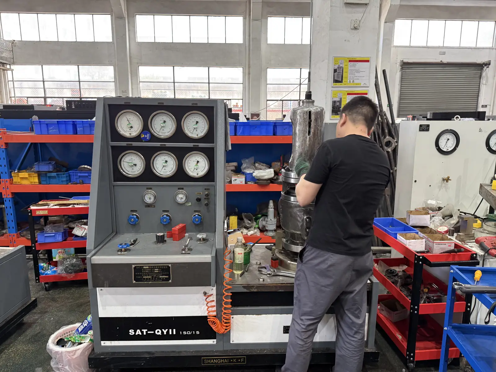
From Code Requirement to Shop-Floor Verification
Standards define technical requirements, but purchase-order compliance depends on design, materials, inspection scope and recorded test results. This actual ZOBAI photograph documents pressure-test control panel and safety valve technician. It is facility evidence, not a substitute for project-specific certificates or an agreed inspection and test plan.
Do not select the valve by pipe size, flange size or standard number alone
Minimum engineering checks
- Confirm the governing relief scenario before calculating capacity or required area.
- Define protected equipment, MAWP, set pressure, allowable overpressure and operating pressure margin.
- Provide required relieving capacity and calculation basis, not only pipe size or flange size.
- State medium phase: gas, vapor, steam, liquid, flashing liquid or two-phase flow.
- Review back pressure, inlet pressure loss, discharge route and installation limitations.
- Request sizing calculation, selected orifice, certified capacity, MTC, set pressure report, pressure test and seat test.
API 520 safety valve sizing application cases with typical RFQ data
Case 1: API 520 Gas PSV for a Natural Gas PRV Station
Case 2: API 520 Steam Safety Valve for Boiler or Header Protection
Case 3: API 520 Liquid Relief Valve for Pump Deadhead
Case 4: API 520 PSV for Compressor Blocked Discharge
Case 5: API 520 Sizing for Fire Case Vessel Relief
Case 6: API 520 RFQ Comparing Required Area and Selected Orifice
Information to send when your project requires API 520 sizing
- Protected equipment: pressure vessel, boiler, pipeline, tank, compressor, reactor, heat exchanger or skid.
- Applicable basis: API 520 Part I, API 521 relief scenario, ASME code, owner specification or local regulation.
- Relief scenario: blocked outlet, fire case, regulator failure, compressor discharge, tube rupture or thermal expansion.
- Design pressure / MAWP, set pressure, overpressure, operating pressure and operating margin.
- Medium name, phase, molecular weight, density, viscosity, vapor/liquid fraction and special hazards.
- Required relieving capacity, relieving pressure, relieving temperature and calculation basis.
- Back pressure, inlet pressure loss, discharge route, silencer, flare, scrubber, vent or drain system.
- Required documents: datasheet, sizing report, selected orifice, MTC, set pressure certificate, pressure test and seat tightness test.