Safety Valve Engineering Guide What Is a High Temperature Safety Valve? Understand how relieving temperature changes materials, seats, springs, capacity, back pressure, piping and documentation decisions before a valve is specified. On this pageQuick AnswerTemperature MeaningPerformance EffectsComponent ReviewConfigurationsFailure ChecksSelection WorkflowRFQ ChecklistFAQ Quick Answer: What Is a High Temperature Safety Valve? A high temperature safety valve …

Safety Valve Engineering Guide
What Is a High Temperature Safety Valve?
Understand how relieving temperature changes materials, seats, springs, capacity, back pressure, piping and documentation decisions before a valve is specified.
Quick Answer: What Is a High Temperature Safety Valve?
A high temperature safety valve is a pressure-relief device selected and configured to protect equipment when the process or relieving condition exposes the valve to elevated temperature. The term does not identify one universal construction, and there is no single temperature above which every valve becomes a “high temperature” valve. Suitability depends on the medium and phase, operating and relieving temperatures, set pressure, required relieving capacity, back pressure, pressure-temperature rating, seat and seal limits, spring exposure, piping loads, applicable code and manufacturer data. From a pressure-protection perspective, temperature matters because it can change fluid properties, material strength, component clearances, sealing behavior and the basis used to calculate capacity. A valve should therefore not be selected from temperature, connection size or body material alone. Before quotation, confirm the protected equipment, credible relief scenario, complete pressure-temperature conditions, required capacity, inlet and outlet arrangement, materials, testing and documentation. Final selection requires project/code review and manufacturer confirmation for the specific valve configuration.
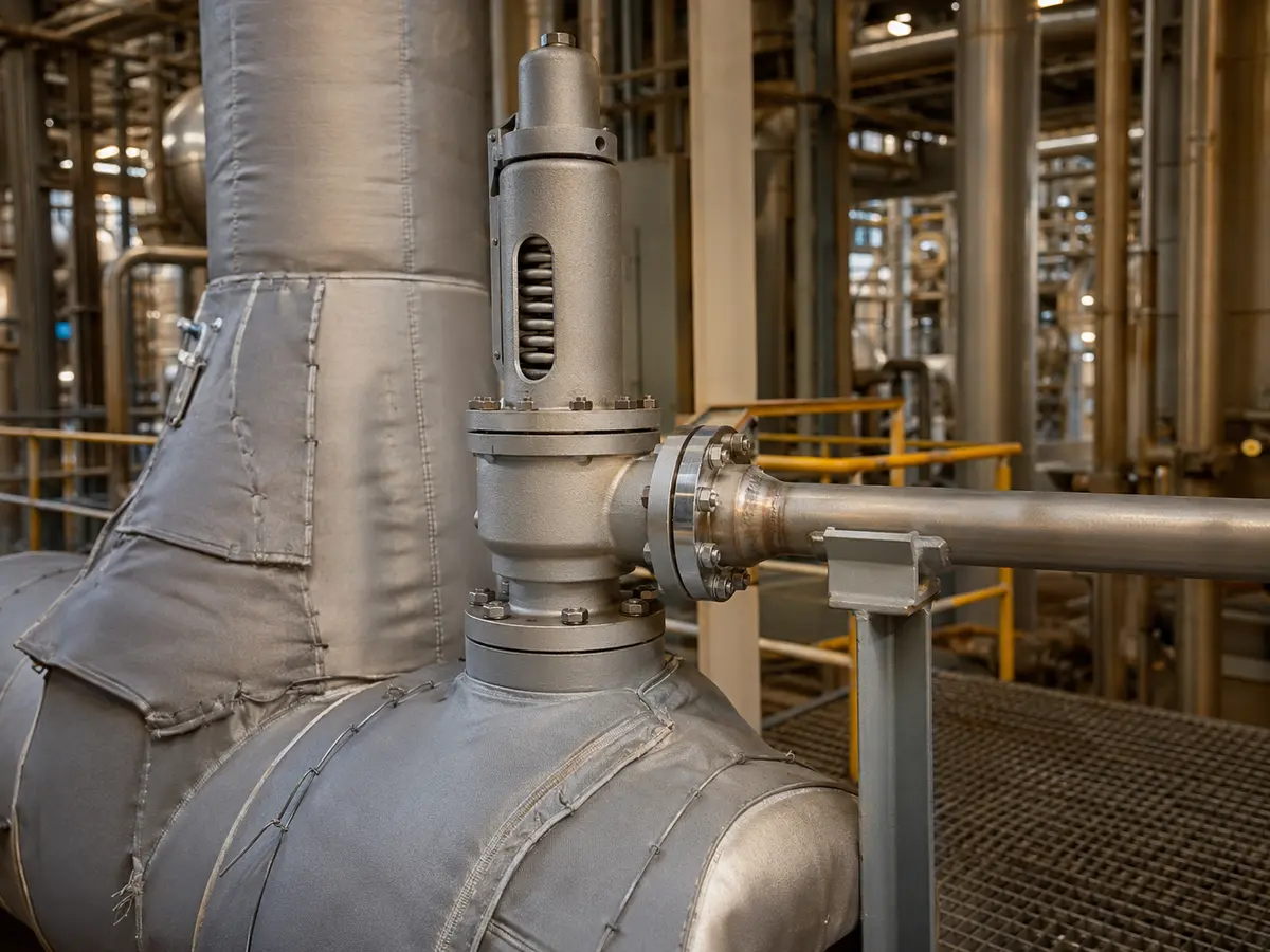
Conceptual industrial image; it does not document a specific valve model, installation or operating result.
For readers comparing available configurations, the separate High Temperature Safety Valves product page can serve as the product-family entry point. This article focuses on why the engineering decision changes when service temperature rises.
What Does “High Temperature” Actually Mean for a Safety Valve?
The useful question is not simply, “What is the line temperature?” It is, “Which temperature applies to each part of the relief case and valve assembly?” A process can have a relatively stable normal temperature but a different relieving temperature during fire exposure, blocked flow, runaway reaction, utility failure or another credible scenario. Conversely, a short relief event may expose the trim differently from continuous hot service.
Process Temperature vs Relieving Temperature
Operating temperature describes normal process conditions. Design temperature is a selected equipment-design basis and should not automatically be substituted for the temperature at the valve during a specific relief event. Relieving temperature is the fluid temperature used for the applicable relief case and capacity calculation. It affects density and other thermodynamic properties, so using normal operating data in place of relieving data can produce an incorrect sizing basis.
| Temperature term | What it describes | Why it matters |
|---|---|---|
| Operating temperature | Normal process condition | Influences continuous exposure, deposits, sealing and operating margin |
| Design temperature | Equipment or piping design basis | Used with the applicable material and pressure-rating rules; not automatically the relief-case temperature |
| Relieving temperature | Fluid condition during the specified relief scenario | Influences fluid properties, sizing inputs and component exposure |
| Ambient temperature | External environment around the valve | Can affect heat loss, weather protection and exposed accessories |
| Component temperature | Actual temperature reached by the body, trim, spring chamber, seals or bellows | Determines whether each component and material remains suitable |
Fluid Temperature vs Component Temperature
Not every component reaches the same temperature as the fluid. Heat transfer depends on valve geometry, flow duration, bonnet arrangement, insulation, ambient conditions and installation. The body and nozzle may see direct process exposure, while the spring chamber may be partly isolated or ventilated. This difference is important, but it should be established from the manufacturer’s design data rather than assumed from appearance.
Why There Is No Universal Temperature Threshold
A temperature that is routine for one metallic construction may exceed the limit of a gasket, elastomer, coating, soft seat, bellows material or accessory on another valve. Pressure also matters: a flange class or body material cannot be evaluated independently of the pressure-temperature combination. The applicable code, adopted edition, service medium and project specification may further change the acceptance criteria. The main selection risk is treating a marketing temperature range as proof that the complete valve assembly is suitable for the actual relief case.
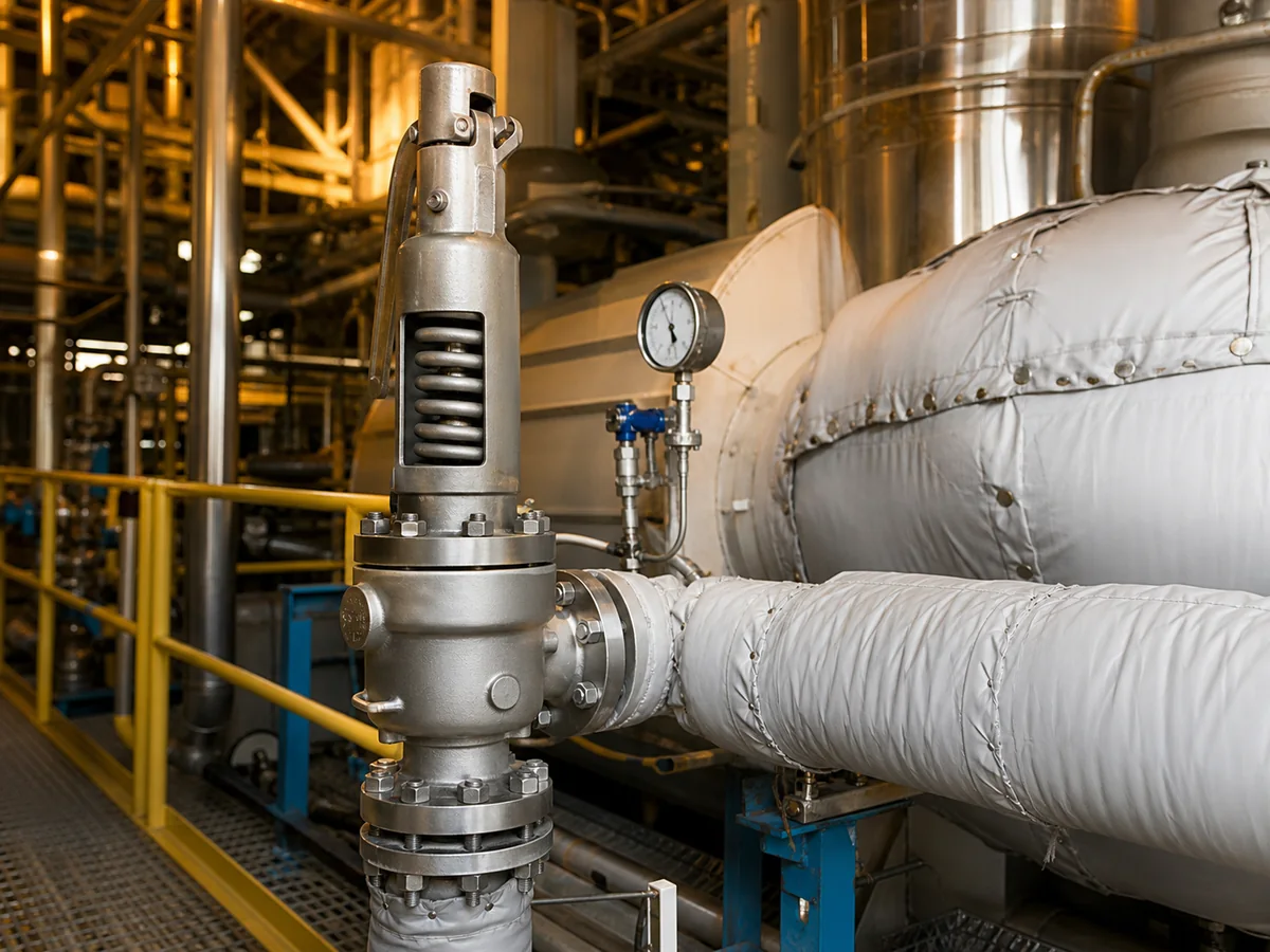
Conceptual heat-transfer illustration—not a temperature prediction for a specific valve model.
How High Temperature Changes Safety Valve Performance
High temperature does not create one predictable failure mode. It changes several interacting factors, and each must be checked against the actual valve design.
Material Strength and Pressure Rating
Allowable pressure or pressure-temperature ratings generally depend on temperature, material group and governing design rules. The body, bonnet, bolting and connections therefore need a combined pressure-temperature review. A named alloy alone does not establish suitability: corrosion, oxidation, hydrogen effects, thermal cycling, fabrication requirements and compatibility with the process medium may also matter.
Spring Stability and Set Pressure
The spring supplies the closing force in a direct spring-loaded safety valve. Excessive spring exposure can affect mechanical behavior and long-term stability, but temperature at the spring cannot be inferred solely from process temperature. Bonnet arrangement, heat flow, discharge frequency and manufacturer design all affect exposure. A high-temperature application may justify an open bonnet, extended bonnet or another thermal arrangement, but none is automatically correct for every medium or installation.
Set pressure is not capacity. It defines an opening-pressure reference under the applicable test and service conditions; it does not state how much mass or volume the valve can relieve. If service conditions require a cold differential test pressure or another temperature-related correction, that requirement must be established and documented under the applicable standard and manufacturer procedure.
The service set pressure is the intended opening reference under in-service conditions; cold differential test pressure (CDTP) is the pressure used to set or verify the valve on a cold test stand after applicable service-temperature and, for relevant conventional designs, back-pressure effects are accounted for. They are not interchangeable. The National Board temperature-considerations article explains that in-service review uses the stamped set pressure, while test-stand performance may be evaluated against CDTP. Any correction must come from the specific manufacturer instructions and adopted project/code basis—not a generic multiplier.
Seat Tightness and Thermal Expansion
Thermal expansion can change alignment, clearances and contact at the nozzle-disc interface. Metal seats are often considered where soft-seat materials cannot tolerate the temperature, but “metal seated” does not establish a specified leakage class. Seat tightness depends on the design, surface condition, operating pressure relative to set pressure, deposits, piping loads, test method and service history. Where the governing specification adopts it, API 527 seat-tightness testing must be applied to the relevant valve type, test medium and acceptance basis rather than treated as a universal leakage guarantee. A soft seat may be feasible only when its material, chemical compatibility and temperature limit are confirmed for the specific design.
Relieving Temperature and Capacity Basis
Capacity must be based on the credible relief scenario and the fluid properties at relieving conditions. Gas, vapor, steam, liquid and two-phase flow require different treatment. Connection size alone does not prove capacity, and valves with the same inlet and outlet sizes can have different effective orifices and documented capacities. The selected valve must have adequate certified or otherwise code-required documented capacity for the governing case, with the calculation method, correction factors and applicable standard confirmed.
| Engineering item | Established by | What must be compared | Do not substitute |
|---|---|---|---|
| Required relieving capacity | Relief-load calculation for the governing credible scenario | Mass or volumetric load, units, phase and relieving properties | Normal process flow or connection size |
| Candidate valve capacity | Applicable certified or otherwise required documented capacity basis | Same fluid basis, pressure, temperature, back-pressure treatment and configuration | Nominal inlet size or an unverified catalogue maximum |
| Selected orifice/configuration | Manufacturer sizing record and project/code review | Available documented capacity must meet the required capacity under the accepted basis | A larger body size without checking stability, inlet loss and blowdown behavior |
| Final acceptance | Responsible engineering authority, manufacturer and any required jurisdictional review | Calculation, datasheet, materials, rating, testing and documentation must describe the same assembly | A product-family temperature statement |
A capacity comparison is valid only when both sides use compatible units and an appropriate basis. A candidate that appears adequate at one published condition may not be adequate after the actual relieving temperature, medium properties, back pressure or approved correction factors are applied.
Thermal cycling, oxidation, erosion, polymerization, coking or other deposits can also restrict movement or damage sealing surfaces. These risks depend on medium composition and operating history, not temperature alone.
Which Components Require Temperature Review?
The complete pressure-relief assembly needs review. Confirming only the body grade leaves important failure paths unchecked.
| Component | Temperature-related review | Typical error to avoid |
|---|---|---|
| Body and bonnet | Material rating, pressure-temperature combination, corrosion and oxidation | Accepting a body grade without checking the assembled valve rating |
| Nozzle, disc and guide | Strength, galling, expansion, erosion, deposits and compatibility | Assuming all trim materials behave alike |
| Spring and spring chamber | Actual exposure, ventilation or isolation, relaxation risk and manufacturer limits | Equating line temperature with spring temperature |
| Seat construction | Metal or soft-seat limit, chemical compatibility, tightness requirement | Treating metal seating as proof of seat tightness |
| Bellows | Material, temperature, pressure differential, fatigue and back-pressure limits | Treating a bellows as a universal cooling device |
| Gaskets, packing and auxiliary seals | Temperature and chemical limits, fire or emissions requirements where applicable | Checking metals but overlooking non-metallic parts |
| Flanges and bolting | Class or PN rating at temperature, material group and mating compatibility | Selecting from nominal size and pressure class alone |
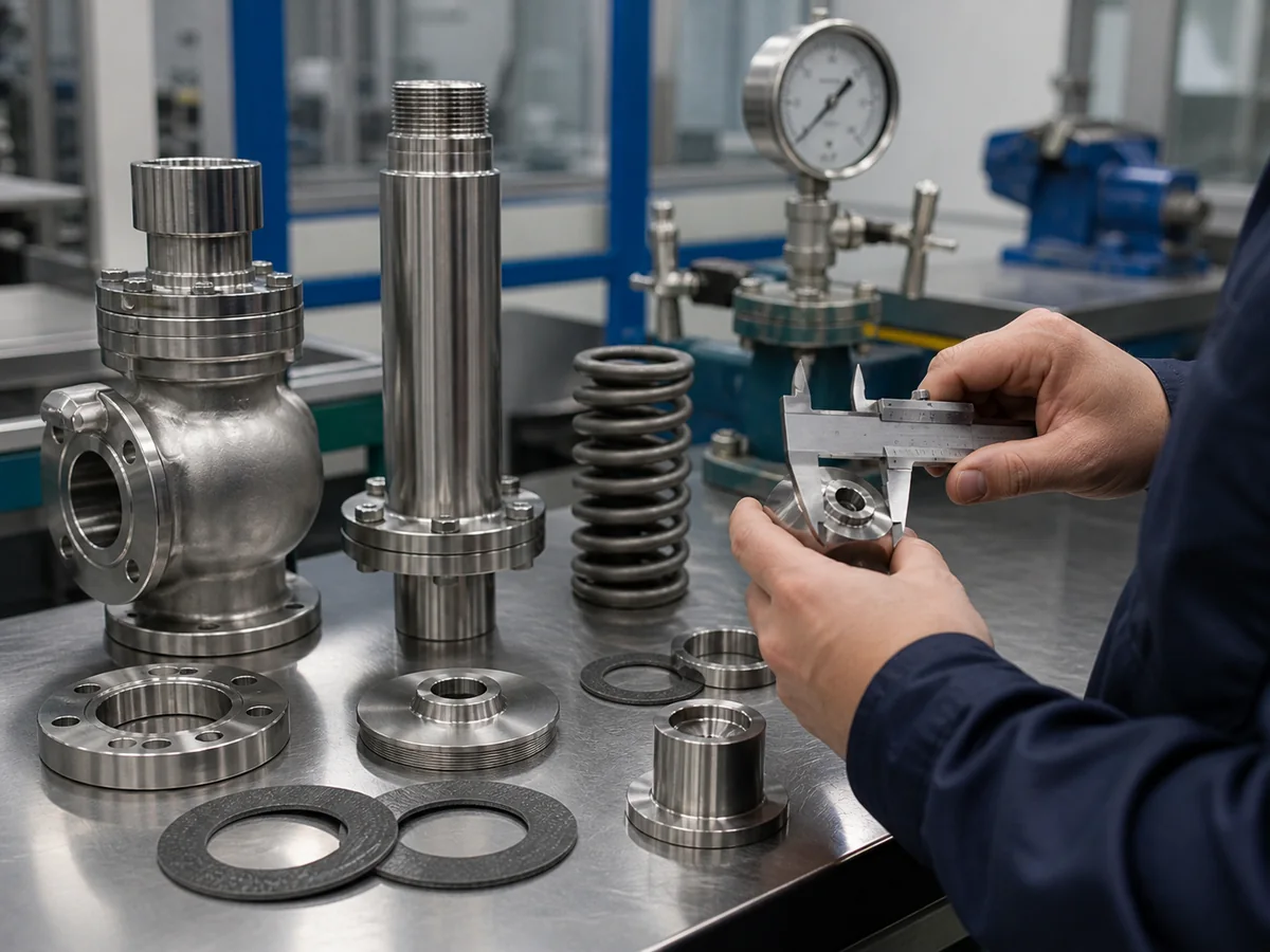
Representative spring-loaded construction; individual models may use different components or arrangements.
Pressure-Retaining Parts
Body, bonnet, flanges, bolting and any adapters must remain acceptable at the required pressure-temperature combination. The weakest pressure-boundary component may govern.
Trim and Seat
Nozzle, disc, guide and seat require temperature, medium and degradation-mechanism review. Dirty, oxidizing, corrosive, viscous or solidifying service also needs a deposit and movement-risk plan.
Spring and Bonnet Arrangement
An open bonnet may aid ambient cooling; a closed bonnet may protect or contain the spring chamber. Leakage paths, emissions, weather and personnel exposure govern the arrangement; neither is universally superior.
Gaskets, Bellows and Auxiliary Seals
Bellows may reduce some back-pressure effects or isolate components, but retain their own pressure, temperature, fatigue and material limits. Check every auxiliary seal, gasket and packing item; a stainless-steel valve can still contain temperature-limited non-metallic parts.
Common High Temperature Safety Valve Configurations
This section explains why a configuration enters engineering review; available ZOBAI models, ratings and commercial scope remain owned by the product-family page linked above. The configuration must follow the relief case, medium, back pressure, discharge arrangement and maintenance needs.
| Configuration | Why it may be considered | Boundary that still requires confirmation |
|---|---|---|
| Spring-loaded valve | Direct mechanical operation and broad industrial use | Spring exposure, blowdown, back pressure, capacity and service compatibility |
| Open bonnet | Can allow heat dissipation around the spring in suitable service | Not automatically suitable for hazardous, corrosive or weather-exposed conditions |
| Closed bonnet | Protects or contains the spring chamber depending on design | Internal temperature and venting arrangement must be reviewed |
| Metal seat | Avoids some soft-seat temperature limits | Tightness, material pairing, finish and operating margin still matter |
| Balanced bellows | May reduce back-pressure effects and isolate bonnet parts | Bellows temperature, fatigue, material and allowable back-pressure limits |
| Extended or cooling arrangement | May reduce heat reaching temperature-sensitive components | Effectiveness must come from manufacturer data for the specific assembly |
| Jacketed construction | May keep viscous or solidifying media mobile | It controls medium temperature for flow assurance; it is not synonymous with high-temperature relief protection |
Open vs Closed Bonnet
Open bonnet safety valves may aid spring-area heat dissipation in suitable service; closed bonnet safety valves may support containment or environmental protection but can alter spring-chamber temperature. Medium hazards, surroundings, venting and manufacturer data govern the choice.
Metal Seat vs Temperature-Limited Soft Seat
Metal seats avoid some non-metallic temperature limits but do not guarantee tightness. Seat criterion, material pairing, medium cleanliness, cycling and maintenance still apply. A soft seat requires verified compatibility and temperature limits for the exact construction.
Bellows and Back Pressure
Superimposed back pressure and built-up back pressure are different conditions: the former exists before opening; the latter develops during discharge. A balanced bellows may reduce some effects, but allowable magnitude, variability, bellows rating, venting and failure detection remain configuration-specific. Outlet piping still requires hydraulic and mechanical review.
| Back-pressure question | Evidence required | Why high temperature matters | Decision boundary |
|---|---|---|---|
| Is superimposed back pressure present before opening? | Minimum, normal and maximum pressure; constant or variable behavior | Header conditions and gas properties can change with temperature | Do not treat one normal header-pressure value as the full range |
| How much built-up back pressure develops during relief? | Outlet-system calculation for the governing simultaneous-flow case | Density, expansion and downstream heat transfer affect pressure loss | Do not infer it from outlet nominal size alone |
| Can the proposed valve tolerate the total effect? | Manufacturer limits for the exact conventional, balanced or pilot-operated configuration | Bellows, seals, pilot components and discharge parts have temperature limits | Do not assume “balanced” means unlimited back pressure |
| Is the discharge system mechanically acceptable? | Reaction forces, supports, thermal expansion, drainage and vent routing | Hot discharge can impose thermal movement and additional loads | Hydraulic acceptance does not replace mechanical piping review |
When Heating or Cooling Features May Be Considered
Cooling or extended-bonnet features may protect temperature-sensitive components; jackets or tracing may maintain flow for viscous or solidifying media. These are different purposes, and their effectiveness and interfaces require manufacturer review.
Do not select by configuration label alone. Stop the preliminary selection if the governing relief scenario, phase at the valve, required capacity, relieving temperature, total back-pressure range or pressure-temperature rating is unknown. “High temperature,” “metal seat,” “open bonnet” and “balanced bellows” describe considerations—not proof that the complete assembly is suitable.
Where Are High Temperature Safety Valves Used?
Steam and Superheated Steam
Use steam properties at relieving conditions and verify capacity, discharge loads and the applicable boiler or pressure-equipment rules. Open-bonnet or lever arrangements are code- and design-dependent, not automatic high-temperature requirements.
Thermal Oil Service
Treat thermal oil as liquid unless the credible case produces flashing or two-phase flow. Recalculate capacity and review degradation, coking, materials, seats, drainage and hot-discharge containment rather than transferring a steam configuration.
Hot Gas and Process Vapor
Composition, fluid properties, toxicity, flammability and downstream pressure matter. A closed header requires the valve and outlet system to be checked together for superimposed and built-up back pressure.
Viscous or Solidifying Media
Viscosity, polymerization, crystallization or solidification can obstruct flow or movement. Document the minimum flowing temperature, tracing or jacket scope, drainage and cleaning plan; added heat can also accelerate degradation.
What Can Go Wrong in High Temperature Service?
Symptoms should be investigated as evidence, not treated as proof of a single cause.
| Observed condition | Possible contributors | Checks before deciding corrective action |
|---|---|---|
| Seat leakage | Thermal distortion, damaged seating surfaces, deposits, excessive operating pressure, piping loads or back pressure | Operating/set-pressure relationship, test history, alignment, seat condition and system pressure |
| Unstable opening or chatter | Excessive inlet loss, oversized valve, variable flow, back pressure or unsuitable installation | Relief case, inlet calculation, capacity, blowdown behavior and discharge system |
| Restricted movement | Oxidation, coking, corrosion, solidification or guide damage | Medium history, temperature profile, internal inspection and cleaning procedure |
| Set-pressure concern | Spring exposure, incorrect adjustment, service change or test-condition mismatch | Nameplate, test records, spring chamber condition and approved test procedure |
| Bellows damage | Temperature, corrosion, fatigue or pressure beyond design limits | Bellows material/rating, vent condition, back pressure and inspection findings |
| Nozzle or flange leakage | Gasket limit, bolting relaxation, thermal gradients or external piping loads | Joint rating, assembly records, supports and measured alignment |
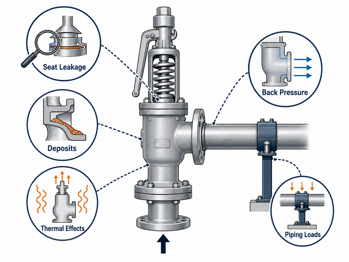
Illustrative inspection framework; testing and repair require controlled isolation and qualified procedures.
Unapproved bonnet insulation can retain unwanted heat; missing inlet heat maintenance can allow solidification. Show insulation and tracing boundaries on the installation drawing.
Calculate inlet loss, outlet back pressure and thermal loads for the governing case, then check manufacturer limits, applicable code and the project’s safety valve installation requirements. Never adjust or dismantle the valve under pressure; use controlled isolation and qualified procedures.
High Temperature Safety Valve Selection Workflow
Preliminary Selection Matrix
Use this matrix to decide what needs engineering review before a candidate construction is discussed. It is a screening tool, not a product recommendation.
| Service evidence | Initial review direction | Required confirmation | Unsafe shortcut |
|---|---|---|---|
| Clean steam or vapor at elevated relieving temperature | Spring exposure, bonnet arrangement, documented steam/gas capacity and discharge loads | Relieving properties, pressure-temperature rating, code rules and outlet design | Choosing an open bonnet because the line is hot |
| Hot hazardous or corrosive vapor | Containment, bonnet/vent routing, trim compatibility and closed-header effects | Composition, emissions boundary, corrosion mechanism and back pressure | Using an exposed arrangement without a release-path review |
| Hot liquid that may flash | Phase determination and liquid/two-phase sizing basis | Inlet and downstream pressure, relieving temperature and fluid properties | Sizing as non-flashing liquid from operating conditions |
| Viscous, polymerizing or solidifying medium | Flow assurance, deposits, inlet geometry, drainage and maintenance access | Minimum flowing temperature, tracing/jacket scope and cleaning procedure | Adding a jacket without checking degradation or relief capacity |
| Discharge to a common pressurized header | Total back-pressure analysis and configuration screening | Superimposed range, built-up pressure, simultaneous cases and manufacturer limits | Assuming a bellows solves every header condition |
Step 1: Define the Relief Case
Identify the protected equipment, credible overpressure causes, governing required load and discharge phase. Use the project-adopted edition and scope of API 521 relief-scenario guidance where applicable. Temperature belongs to the relief scenario, not an isolated line-data field.
Step 2: Establish Pressure and Temperature Conditions
Record operating pressure, MAWP/design pressure as applicable, set pressure, overpressure or accumulation basis, operating and relieving temperatures, ambient extremes and transients. Do not substitute design pressure for another code-defined value.
Step 3: Verify Capacity and Back Pressure
Apply the project-adopted API 520 sizing and selection basis where applicable, then compare the calculated required load with the certified or otherwise required documented valve capacity on a compatible basis. Include both forms of back pressure, header behavior and configuration-specific corrections.
Step 4: Review Materials and Configuration
Check the complete assembly against temperature, corrosion, deposits, cycling and containment needs. Confirm connection ratings, orientation, supports and insulation boundary.
Step 5: Confirm Documentation
State the code, edition and project specification, then define capacity, materials, testing, inspection and jurisdictional documentation. A standard name alone is incomplete.
Composite Engineering Scenarios
The following are composite engineering scenarios for training. They do not describe a customer, installed project, certified capacity or recommendation for a particular model.
Scenario A: Superheated Steam Service
A steam header has an elevated relieving temperature. The team establishes the governing mass load using relieving steam properties, then checks rating, documented capacity, trim, spring exposure, inlet loss and discharge loads. An open bonnet is only a candidate after code, environment and personnel exposure are reviewed.
Scenario B: Thermal Oil System
A heat-transfer loop has blocked-flow and fire cases. The team determines whether the governing discharge remains liquid, flashes or becomes two-phase, then reviews degradation, coking, drainability and disposal. Metal seats or jackets remain conditional on leakage, fluid behavior and installation.
Scenario C: Hot Gas with Back Pressure
A vessel relieves hot gas into a common header with variable superimposed and built-up back pressure. The team models both forms, verifies piping losses and screens conventional, bellows-balanced or pilot-operated arrangements against documented limits. Bellows temperature, fatigue, venting and failure behavior still require review.
Inspection and Documentation Checks
Before Purchase
Complete the RFQ fields below and identify every unresolved engineering input before requesting a configuration.
Before Installation
Match the delivered valve to the approved datasheet, then verify connections, orientation, piping loads, drainage, insulation/tracing boundaries and manufacturer installation instructions.
| Do | Why | Do not | Risk created |
|---|---|---|---|
| Keep the inlet direct and verify calculated inlet loss | Supports stable valve operation for the governing flow case | Use long, reduced or pocketed inlet piping without review | Pressure loss, deposits or unstable opening |
| Support outlet piping independently and assess reaction loads | Limits external load on the valve and connected nozzle | Use the valve body as the sole support for a heavy hot discharge line | Misalignment, joint leakage or mechanical damage |
| Follow the approved insulation, tracing and drainage drawing | Maintains the intended component temperatures and flow path | Wrap the bonnet, vent or spring chamber by field judgement | Heat retention, blocked venting or hidden leakage |
| Provide safe access and route hot discharge or vents correctly | Supports inspection without placing personnel in a release path | Discharge toward walkways or locate access in the reaction zone | Personnel exposure during lifting or leakage |
Before Return to Service
Confirm qualified repair, required set-pressure and seat-tightness records, approved internal parts and adjustments, correct isolation-valve positions, and restoration of vents, drains, supports, insulation and weather protection. Retain records under project and jurisdictional requirements.
Test and Document Matrix
| Record or verification | What it should identify | Why it matters | Project-specific boundary |
|---|---|---|---|
| Approved datasheet and sizing record | Relief case, properties, required load, selected configuration and capacity basis | Connects the process calculation to the supplied valve | Required format and approval responsibility vary by project |
| Set-pressure test record | Valve identity, test medium, test conditions, result and authorized procedure | Shows what was tested without implying service performance at every temperature | Cold differential test pressure or correction must be defined where applicable |
| Seat-tightness test record | Applicable method, acceptance criterion and tested configuration | Prevents “metal seat” from being treated as a leakage guarantee | Criterion depends on the governing specification and service |
| Material and configuration records | Pressure parts, trim, seat, spring, bellows, gaskets and bolting as required | Confirms that temperature review applies to the delivered assembly | Record scope and traceability level must be stated in the purchase order |
| Installation and maintenance records | Orientation, supports, insulation/tracing, vents, repairs and replacement parts | Preserves the assumptions used during selection | Inspection interval and repair authorization follow project and jurisdictional rules |

The checklist supports quotation preparation but does not replace relief-load calculation or project-code review.
RFQ Checklist for High Temperature Service
Connection size alone does not prove capacity. Before quotation, provide the following data or identify each item that still requires engineering confirmation.
| RFQ field | Information required |
|---|---|
| Protected equipment | Vessel, boiler, exchanger, line or other equipment being protected |
| Relief scenario | Fire, blocked outlet, thermal expansion, utility failure, reaction or other credible case |
| Medium and phase | Composition; gas, vapor, steam, liquid or two-phase behavior |
| Temperature | Operating, design and relieving temperatures; ambient or transient limits if relevant |
| Pressure | Operating pressure, MAWP/design pressure, set pressure and applicable overpressure/accumulation basis |
| Capacity | Required relieving capacity, units and calculation basis |
| Back pressure | Constant or variable superimposed pressure and expected built-up pressure |
| Connections and piping | Inlet/outlet sizes, standards, ratings, facing, inlet-loss data and discharge arrangement |
| Materials | Body, trim, seat, spring, bellows, gasket and bolting requirements; corrosion concerns |
| Configuration | Bonnet, lever/cap, bellows, heating/cooling or accessory requirements where applicable |
| Standards and documents | Governing code and edition, certification, test reports, material records and inspection requirements |
| Commercial context | Quantity, delivery location and existing datasheet or nameplate information |
Technical References
Use the editions adopted by the project, owner and jurisdiction. These official pages describe the standards and their scope; they do not replace the applicable documents or prove that a specific valve is certified.
- API 520 Part I — sizing and selection of pressure-relieving devices within its stated scope.
- API 520 Part II — installation considerations within its stated scope.
- API 521 — pressure-relieving and depressuring system guidance within its stated industries.
- ASME Boiler and Pressure Vessel Certification — official certification-program context.
- ISO excessive-pressure protection catalogue — official catalogue entry for the ISO 4126 family.
- National Board: Temperature Considerations for Pressure Relief Valve Application — technical context for service set pressure, CDTP and temperature effects.
Frequently Asked Questions
What temperature is considered high for a safety valve?
There is no universal threshold for every safety valve. The relevant limit depends on pressure, medium, valve design, materials, seats, seals, spring exposure, applicable code and manufacturer data.
Is there a universal maximum temperature for safety valves?
No. A maximum temperature must apply to a defined valve configuration and pressure range. The lowest acceptable limit among pressure-retaining parts, trim, seats, seals, bellows, gaskets and accessories may control.
Why is relieving temperature different from operating temperature?
Operating temperature describes normal service. Relieving temperature belongs to a particular overpressure scenario and is used with the fluid properties and capacity calculation for that case. They may be similar, but should not be assumed identical.
Are metal seats always required for high temperature service?
Not automatically. Metal seats avoid some non-metallic temperature limits, but seat material pairing, tightness, deposits and maintenance still matter. A soft seat is acceptable only when the exact material and construction are verified for the service.
Is an open bonnet always better for high temperature service?
No. It may assist heat dissipation in suitable applications, but a closed arrangement may be needed for containment, environmental protection or another design reason. Medium hazards and manufacturer data govern the choice.
Can insulation affect safety valve performance?
Yes. Insulation can change component temperatures. Covering a bonnet or spring chamber may retain unwanted heat, while insufficient heat maintenance can allow some media to solidify. Follow the approved installation and insulation design.
How does high temperature affect safety valve capacity?
Temperature changes fluid properties used in sizing and can affect applicable correction factors or documented valve limits. Required capacity must be calculated for the governing relieving condition and checked against the documented capacity of the proposed valve.
What information should be included in a high temperature safety valve RFQ?
Include the protected equipment, relief scenario, medium and phase, operating and relieving conditions, MAWP/design pressure, set pressure, required capacity, back pressure, connections, materials, applicable standards, testing and document requirements.
Send Your High Temperature Service Conditions for Review
Submit the completed RFQ data, existing datasheet and clear nameplate information where available. Appearance, nominal size, temperature and set pressure alone are not a safe replacement basis.
Use the confirmed Ask a Safety Valve Engineer page to request a configuration review. Final acceptance remains subject to complete project data, manufacturer documentation, the adopted code edition and local requirements.
Technical Use Boundary
Prepared as: ZOBAI Engineering Content Team
Use boundary: Apply this article as an engineering screening and RFQ-preparation guide. Record any project-specific technical approval in the project documentation, not as an unsupported claim on this page.
This engineering explainer supports RFQ preparation. It does not replace a relief-load study, code calculation, manufacturer sizing record, installation review, inspection or jurisdictional approval.
Standards and Limitations
Applicable requirements depend on the protected equipment, jurisdiction, adopted code edition, service and project specification. Naming API 520, API 521, ASME BPVC or ISO 4126 does not establish compliance or complete a valve specification. Confirm the adopted edition, mandatory local rules, manufacturer limits, documented capacity, materials, testing and documentation for the actual project.