Engineering Selection Guide Select the changeover valve as part of the complete relief path A PRV changeover valve must keep one qualified pressure-relief path available during operation, switching and maintenance. Select it by verifying the active PRV capacity, selector flow resistance, inlet loss, outlet back pressure, isolation integrity, materials and operating controls—not by connection size …

Engineering Selection Guide
Select the changeover valve as part of the complete relief path
A PRV changeover valve must keep one qualified pressure-relief path available during operation, switching and maintenance. Select it by verifying the active PRV capacity, selector flow resistance, inlet loss, outlet back pressure, isolation integrity, materials and operating controls—not by connection size or valve count alone.
- Capacity
- Flow restriction
- Back pressure
- Safe isolation
- RFQ data
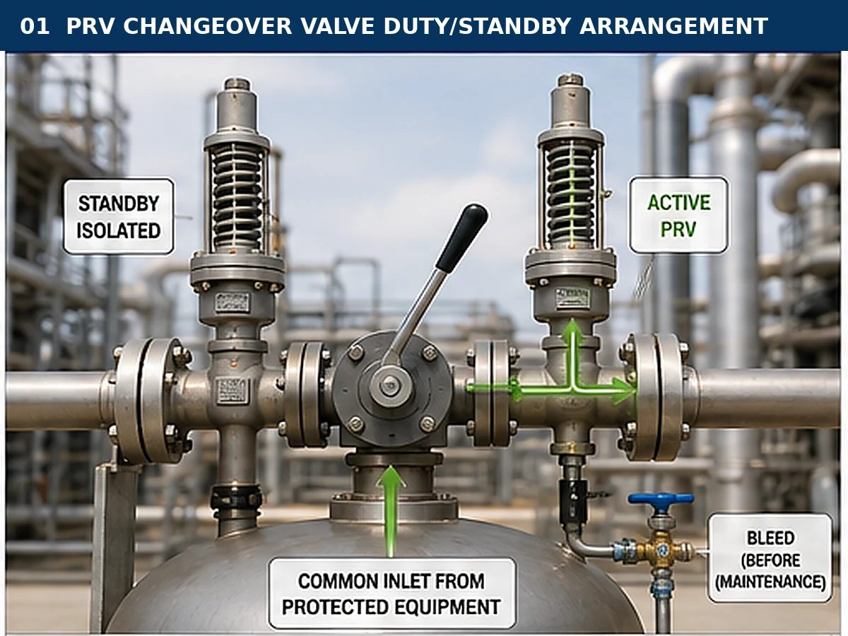
Conceptual industrial representation; final configuration must be verified against the selected valve design and project piping.
Quick selection answer
Select the changeover valve as part of the complete active relief path. One selectable PRV must independently satisfy the governing relief case, and every permitted selector position must avoid unacceptable inlet loss, outlet restriction, mismatched inlet/outlet routing or simultaneous isolation.
Before quotation, confirm the protected equipment, relief scenario, medium and phase, operating pressure, MAWP or design pressure, set pressure, required relieving capacity, relieving temperature, selector resistance, superimposed and built-up back pressure, connections, materials and required documents. Connection size and set pressure do not prove capacity. Final selection requires PRV capacity evidence, manufacturer data for the exact selector, complete inlet and outlet piping review, the adopted code basis, project specifications and local requirements.
Do not proceed to model selection yet if any of these items are unresolved:
- The governing relief case or required relieving rate is unknown.
- Neither selectable PRV has capacity evidence for the actual medium and relieving condition.
- The selector manufacturer cannot provide the active-port geometry or flow-resistance basis.
- The switching sequence can isolate both branches, mismatch inlet and outlet positions, or trap pressure without a controlled bleed path.
1
Define the relief caseIdentify the protected equipment, credible overpressure scenario, fluid condition and required relieving rate.
2
Verify the active PRVConfirm one selected PRV can satisfy its assigned duty using certified or documented capacity data.
3
Review the selectorCheck internal flow area, pressure loss, allowed positions, locking and position indication.
4
Review the dischargeDetermine whether inlet-only or tandem switching is required and calculate back pressure.
5
Confirm materialsReview pressure-temperature ratings and all critical body, trim, seat, seal and packing materials.
6
Prepare the RFQSend the P&ID, relief basis, PRV data, selector requirements and documentation scope.
What must a PRV changeover system accomplish?
Its purpose is operational continuity, not automatic capacity multiplication. The approved switching sequence must preserve an available relief path and allow the inactive branch to be isolated and depressurized safely.
In this guide, PRV means pressure relief valve, not pressure-reducing valve. A changeover system keeps one PRV connected while the other is available for standby or maintenance.
Duty/standby
One PRV is active and one is reserved for standby or maintenance rotation. The active device is normally reviewed against the full assigned relief case.
Parallel or staged relief
Two or more PRVs may intentionally contribute to the required relieving capacity. Set-pressure relationships, accumulated capacity and discharge interaction must be engineered separately.
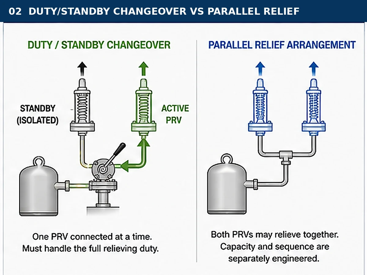
Simplified engineering illustration; actual code treatment and operating philosophy depend on the project.
Main selection risk: an external handle or indicator may not prove the internal port is fully open. Verify stops, linkage, travel, port alignment and the manufacturer operating instructions.
First decide whether changeover architecture is appropriate
Establish the pressure-protection architecture before selecting the device. The deciding question is whether one PRV is standby or whether multiple PRVs are intended to contribute capacity.
Suitable duty/standby applications
- The equipment must remain protected while one PRV is inspected or repaired.
- Either selectable PRV can independently satisfy the governing case.
- The project and applicable code permit the arrangement.
- The inactive side can be isolated and depressurized without simultaneous isolation.
When parallel or staged relief may be required
Use a separately engineered parallel or staged arrangement when the required load exceeds one PRV, when devices intentionally share capacity or when staged set pressures are part of the design. Capacity contribution, accumulation and discharge interaction then require their own review.
Architecture decision gate
| Project intent | Likely architecture | Evidence required before selection | Boundary |
|---|---|---|---|
| Maintain protection while one PRV is removed | Duty/standby changeover | Proof that either selectable PRV can independently satisfy the assigned case | The standby device is not added capacity while isolated |
| Two PRVs must relieve together | Parallel or staged system | Capacity split, set-pressure relationship, accumulation and discharge review | A one-at-a-time selector may be incompatible with the design intent |
| Different relief cases use different devices | Scenario-specific multiple-device arrangement | Case allocation, connectivity and failure-state review | Do not assume one selector position protects every scenario |
| Existing single-PRV system is being converted | Retrofit changeover arrangement | Updated relief basis, nozzle loads, dimensions, access and management of change | Redundancy cannot be added by piping fit-up alone |
For broader valve-family decisions, use the safety valve selection guide. For commercial product scope and configuration questions, review changeover safety valves.
Define the protected equipment and governing relief scenario
Start with the protected equipment and the scenario that creates the required relieving load.
Protected equipment
- Pressure vessel or reactor
- Heat exchanger
- Compressor or pipeline system
- Storage or process tank
- Boiler, steam equipment or packaged skid
Credible relief scenarios
- Blocked outlet
- Control or regulator failure
- External fire
- Tube rupture
- Thermal expansion
- Loss of cooling or another project-specific case
Pressure definitions that must not be mixed
| Term | Engineering meaning | Selection consequence |
|---|---|---|
| Operating pressure | Normal pressure during service | Influences operating margin and leakage risk |
| MAWP or design pressure | Equipment pressure limit under the governing design basis | Used with the applicable code to control set pressure and accumulation |
| Set pressure | Pressure at which the PRV is adjusted to begin its specified opening behaviour | Does not prove required or certified capacity |
| Overpressure | Pressure increase above set pressure during relief | Part of the relieving condition and capacity basis |
| Accumulation | Pressure increase above the equipment reference limit during an event | Must remain within the applicable code and scenario limits |
| Relieving pressure | Pressure used for the capacity calculation | Must correspond to the selected fluid method and PRV data |
| Blowdown | Difference between set and reseating pressures | Affects closing behaviour and process operating margin |
Medium, phase and relieving temperature
Confirm steam, gas, vapor, liquid, flashing or two-phase conditions at relief. Capacity methods are not interchangeable, and relieving temperature affects density, materials, pressure-temperature rating, seats and discharge behaviour.
For relief-scenario and disposal-system context, review the ZOBAI guide to API 521 pressure relief systems.
Verify each selectable PRV can handle the assigned relief case
The PRV provides relieving capacity; the selector chooses the connected device and adds resistance to the active path. Review both functions separately and then as one installed system.
Required capacity versus certified or documented capacity
Separate the required relieving rate, calculated area, selected orifice and certified or documented capacity. The evidence must match the medium, relieving pressure, temperature and relevant back-pressure condition.
Why connection size is not capacity
A nominal connection defines the piping interface, not the effective orifice, selector port, coefficient, pressure loss or capacity. Devices with the same connections can have different internal flow areas and ratings.
Active relief path verification
| Verification item | Engineering evidence | Decision effect | What cannot be used as proof |
|---|---|---|---|
| Required relieving capacity | Approved relief calculation for the governing scenario | Defines the duty that the active PRV must cover | Equipment nozzle size or historical valve size |
| Selected PRV capacity | Certified or documented capacity for the correct medium and relieving conditions | Confirms the selected active device can meet the assigned load | Set pressure, inlet size or visual similarity |
| Selector resistance | Minimum port area, Cv/Kv, pressure-drop curve or equivalent manufacturer data | Enters the active inlet- or outlet-path loss review | Matching flange size or the term “full port” without data |
| Installed inlet loss | Calculation covering nozzle, pipe, fittings, selector and active branch | Supports stable PRV operation and the project installation limit | A selector-only pressure-drop value |
| Outlet condition | Superimposed and built-up back-pressure review for each valid position | Confirms capacity, stability and configuration suitability | Normal header pressure alone |
Unsafe shortcut: selecting the PRVs and selector from flange size alone. Mechanical compatibility is necessary, but active-path capacity and pressure loss still require evidence.
Use the safety valve sizing and certified capacity guide for the required-versus-documented capacity relationship, and the API 520 safety valve sizing guide for standards-oriented RFQ interpretation.
Check the changeover valve flow path and pressure drop
The selector is part of the inlet path and, in some configurations, the outlet path. Its resistance belongs in the installed-system review.
Request exact flow information
- Minimum internal flow area or bore
- Cv, Kv or other manufacturer resistance data
- Active flow path in each permitted position
- Internal turns, reducers and port-overlap geometry
- Pressure-drop data for the exact size and configuration
Review the complete inlet path
Include the equipment nozzle, pipe, fittings, reducers, selector and active branch. Excessive inlet loss can destabilize opening, but oversizing, insufficient sustainable flow, back pressure, piping load and valve condition must also be checked.
Failure chain: a restricted selector increases inlet loss; inlet pressure falls as flow starts; stable lift may be lost; cycling, chatter, seat damage or reduced delivered capacity can follow. Correct the system cause rather than making an unsupported PRV adjustment.
Composite engineering example: a replacement selector matches the flange size but has a smaller port and an extra turn. Fit-up is acceptable, but hydraulic equivalence is not. Obtain exact resistance data and recalculate the complete inlet path before approval.
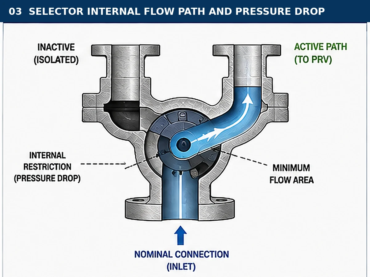
Simplified engineering illustration; it is not a manufacturing drawing for a specific model.
Choose inlet-only or coordinated inlet-and-outlet switching
Select the arrangement from the discharge-system design.
Inlet-only changeover
An inlet-only selector may suit independent safe discharges when the inactive outlet needs no coordinated isolation. Still review drainage, reaction, support and outlet-side pressure.
Tandem inlet and outlet changeover
A tandem arrangement coordinates inlet and outlet selectors to connect the same PRV. It may be required for closed headers, inactive-side outlet isolation or project interlocking.
Configuration decision table
| Discharge condition | Preliminary configuration | Must be checked | Main failure mode |
|---|---|---|---|
| Two separate open discharges | Inlet-only changeover may be possible | Safe discharge, drainage, reaction loads and inactive-side exposure | Unsafe outlet routing or liquid accumulation |
| Common closed discharge header | Tandem inlet/outlet switching may be required | Header pressure, selector resistance, branch isolation and coordinated positions | Active inlet connected to the wrong outlet branch |
| Variable header pressure | Project-specific tandem or alternative arrangement | Maximum and minimum superimposed pressure in each selector position | Unstable operation or unsuitable PRV configuration |
| Inactive PRV must be fully removed from header pressure | Coordinated outlet isolation | Trapped pressure, bleed route and safe maintenance state | Maintenance begins on a pressurized outlet cavity |
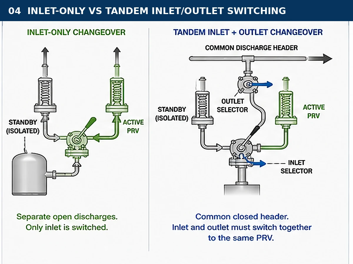
Simplified engineering illustration; the required arrangement depends on back pressure, discharge design and project requirements.
Tandem boundary: inlet and outlet selectors must connect the same PRV; mismatched positions invalidate the intended relief path.
Evaluate superimposed and built-up back pressure
Back pressure can affect opening, capacity, stability and reseating. Review every valid selector position.
Superimposed back pressure
Pressure present at the outlet before opening; it may be constant or variable.
Built-up back pressure
Pressure generated by relieving flow through outlet piping, selector and disposal system.
A selector does not solve back pressure. Check the actual pressure range and the selected conventional, bellows or pilot-operated PRV limits, including venting, contamination, pressure and temperature.
Back-pressure review by condition
| Condition | Question | Selection consequence | Required input |
|---|---|---|---|
| Constant superimposed pressure | Is pressure present before the active PRV opens? | May affect set-pressure basis and valve configuration | Normal and maximum header pressure |
| Variable superimposed pressure | How widely can outlet pressure change? | May narrow the acceptable operating envelope | Minimum, normal and maximum pressure profile |
| Built-up pressure | What pressure develops at the required relieving rate? | Affects capacity, stability and discharge-system sizing | Outlet selector, branch, header and disposal-system calculation |
| Inactive branch exposure | Can header pressure enter the isolated PRV or trapped cavity? | May require coordinated outlet switching and a bleed plan | P&ID, internal porting and selector-position diagram |
| Liquid pocket or condensate | Can liquid accumulate in either discharge branch? | Adds resistance, corrosion and hydraulic-load risk | Drainage, slope, temperature and operating history |
Composite engineering example: two PRVs discharge to a variable-pressure header. A bellows or pilot design name is not enough; verify the pressure range, selector outlet loss, venting, fluid cleanliness and exact manufacturer limits.
For detailed system behaviour, use the ZOBAI guide to back pressure and bellows.
Verify isolation integrity and safe switching
The switching arrangement must not leave the equipment without an available relief path. The product name alone does not prove every internal position is safe.
Prevent simultaneous isolation
- Verify mechanical linkage, stops, common shaft or other position control.
- Confirm whether ambiguous intermediate positions are possible.
- Define locking and authorization requirements.
- Make sure the external indicator corresponds to the internal port.
Depressurize the inactive side before maintenance
Isolation does not mean pressure-free. Trapped pressure may remain at the inlet, outlet or in selector cavities, so an approved bleed, drain and zero-energy verification method may be required.
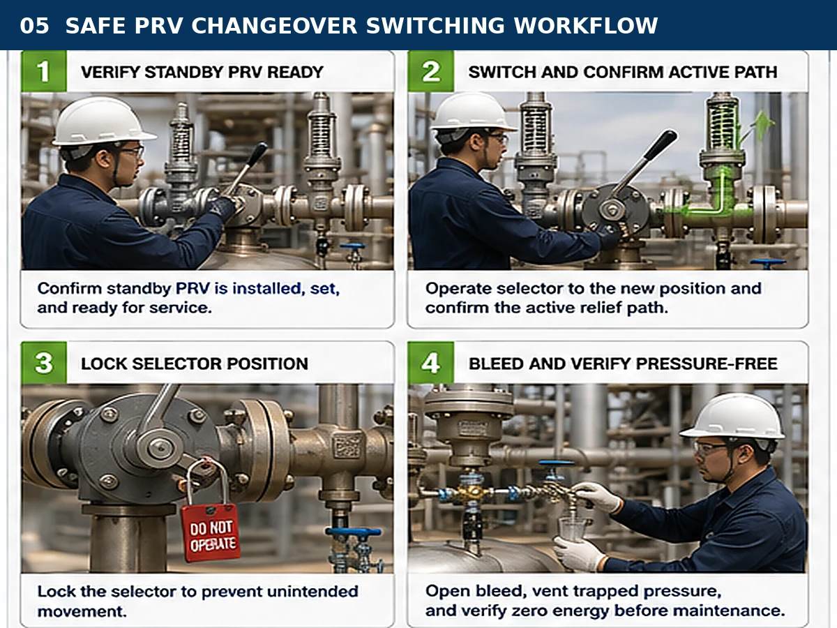
General workflow only; actual switching and lockout procedures must follow the selected model and site requirements.
Evidence that the switching function is acceptable
- Position drawingShows the actual internal port alignment at both end positions and any intermediate positions.
- Mechanical controlDocuments stops, common shaft, linkage, locking or interlock features that prevent an unprotected state.
- Operating procedureDefines authorization, movement-under-pressure limits, active-side verification and final-position control.
- Depressurization planIdentifies trapped volumes, bleed or drain points, safe discharge destination and zero-energy verification.
- Confirm the standby PRV is installed and ready.
- Operate the selector under the approved procedure.
- Verify the new active path and control the selector position.
- Bleed, drain and verify the inactive side is pressure-free.
- Record the final configuration before maintenance.
Select pressure rating, temperature range and materials
Confirm suitability during normal service, relief, standby exposure and maintenance.
Review the complete assembly
- Body and cover
- Flanges or threaded connections
- Stem, shaft or closure element
- Seats and seals
- Packing and gaskets
- Bolting
- Bleed and drain components
- Low- and high-temperature limits
Class or PN and body material do not prove complete-assembly suitability at relieving temperature. Internals can govern corrosion resistance, torque, leakage and switching reliability.
Service-condition screening
| Service condition | Parts that may govern | Failure risk | Data to confirm |
|---|---|---|---|
| Corrosive or sour service | Body, trim, stem, seats, seals, bolting and packing | Corrosion, cracking, seizure or loss of containment | Composition, water content, temperature and project material rules |
| Dirty, viscous or polymerizing fluid | Port, cavities, seats, bleed passages and stem guidance | Blockage, high operating torque or incomplete switching | Solids, viscosity, cleaning and flushing requirements |
| Cryogenic service | Pressure boundary, stem, packing, seals and bolting | Brittle failure, contraction leakage or frozen operation | Minimum metal temperature and warm-up conditions |
| High-temperature service | Body rating, packing, gaskets, seals and operator accessibility | Strength loss, leakage or unsafe manual operation | Normal and relieving temperatures plus thermal cycling |
| Hazardous or toxic fluid | Stem sealing, packing, bleed and drain connections | Exposure during switching or maintenance | Containment, purge and safe-disposal requirements |
Check trapped-cavity thermal expansion
Heating trapped liquid can overpressure selector cavities or isolated branches. Review bleed paths and project cavity-pressure controls.
Review installation and mechanical layout
An acceptable selector can become unsafe if the layout increases inlet loss, transfers piping loads or blocks maintenance access.
Inlet path
- Keep the path direct and include the selector in the inlet-loss calculation.
- Check alignment and piping stress.
Outlet path
- Support heavy piping and review thermal and reaction loads.
- Provide drainage and access for switching and PRV removal.
Installation do / do not review
| Do | Why | Do not | Risk created |
|---|---|---|---|
| Support the selector and discharge piping from the structure | Controls weight, thermal and reaction loads | Use PRV bodies to carry heavy outlet piping | Distortion, leakage or impaired operation |
| Keep the active inlet path direct and calculate its loss | Supports stable opening | Add reducers, sharp turns or long branches without review | Excessive pressure loss and chatter |
| Provide access to the handle, lock, indicator and bleed | Allows controlled switching and maintenance | Install the assembly where final position cannot be verified | Human error and unsafe isolation |
| Route drains and vents according to their function | Prevents pockets and unsafe release | Plug a bonnet vent, pilot vent or bleed without model review | Configuration failure or trapped pressure |
| Check orientation against the selected model | Preserves internal operation and drainage | Assume side or inverted mounting is acceptable | Unstable operation or retained liquid |
Use the safety valve installation guide for broader inlet, outlet, support and discharge review.
Check maintenance, testing and operating controls
Before removing the standby PRV
- Identify and verify the active PRV.
- Control and confirm the selector position.
- Isolate, depressurize and drain the standby branch.
- Verify zero energy and hazardous-fluid controls.
- Record the configuration before removal.
After reinstallation
Verify PRV identity, records, materials, gasket and bolting condition, alignment, selector travel and final positions; restore required seals or locks.
Test and document control matrix
| Record or check | What it supports | What it does not prove | Typical review point |
|---|---|---|---|
| As-found set-pressure result | Condition at removal | Installed capacity or selector performance | Compare with service history and prior records |
| As-left set-pressure result | Adjusted opening-pressure condition | Seat tightness, certified capacity or piping suitability | Confirm test basis and resealing requirements |
| Seat-tightness result | Leakage performance under the stated test | Relieving capacity | Review against the applicable test method and acceptance basis |
| Capacity certificate or documented rating | PRV capacity for the stated configuration and fluid basis | Installed-system pressure loss or back pressure | Match manufacturer, model, orifice and configuration |
| Selector functional check | Travel, position indication and locking | Hydraulic equivalence of the active path | Verify both final positions and controlled intermediate travel |
| P&ID and management-of-change record | Approved system configuration | That field piping exactly matches the document | Perform field verification before return to service |
A set-pressure test confirms an opening-pressure condition. It does not independently establish certified relieving capacity or complete installed-system performance.
Replacement and retrofit selection checks
Do not replace a selector by appearance or dimensions alone. A mechanical fit may hide different port area, resistance, direction, materials, seats or locking.
| Existing information | Why it is needed | Can it be accepted alone? |
|---|---|---|
| P&ID and relief calculation | Confirms architecture and governing case | No; verify current process conditions |
| PRV nameplate and datasheet | Identifies set pressure, orifice and capacity basis | No; confirm current certified or documented data |
| Selector model and drawing | Shows internal arrangement and dimensions | No; obtain exact flow-resistance data |
| Flange size and class | Provides connection compatibility | No; does not prove flow area or assembly rating |
| Face-to-face dimensions | Supports retrofit fit-up | No; operating direction and clearance also matter |
| Photographs | Helps identify layout and access | No; hidden porting and materials remain unknown |
Replacement verification workflow
- Recover the design basis. Confirm the equipment, governing case and current relieving capacity.
- Verify both PRVs. Match set pressure, orifice, documented capacity, materials and connections.
- Compare the selector. Check porting, resistance, rating, direction and locking.
- Review installation. Confirm dimensions, loads, back pressure, access, bleed routing and management of change.
Process, capacity or header changes require relief-system review and management of change, not dimensional replacement alone.
PRV changeover valve preliminary selection matrix
| Project condition | Selection impact | Required data | Main risk if missed |
|---|---|---|---|
| Duty/standby maintenance | One active PRV normally carries the assigned case | Governing load and PRV capacity data | Two undersized PRVs treated as adequate |
| Parallel or staged relief | A different architecture may be required | Capacity split, set pressures and sequence | Insufficient combined capacity |
| Separate open discharge | Outlet selector may not be required | Safe destination, drainage and reaction | Unsafe discharge or inactive-side exposure |
| Common closed header | Coordinated outlet switching may be needed | Header pressure and piping layout | Excessive back pressure or mismatched outlet |
| Restricted selector port | Resistance enters the inlet-loss review | Bore, Cv/Kv or pressure-drop data | Chatter, instability or reduced capacity |
| Corrosive or dirty service | Internals, seats and cavities need detailed review | Composition, solids, viscosity and cleaning needs | Seizure, blockage or leakage |
| Extreme temperature | Assembly rating, packing and seals are critical | Operating and relieving temperatures | Brittle failure, loss of strength or leakage |
| Retrofit | Dimensions and operating direction must match | GA, P&ID, measurements and photographs | Installation mismatch or reversed operation |
Common selection mistakes
Two valves = double capacity
Not in normal duty/standby service; the active PRV generally carries the assigned case.
Same flange size = same flow path
Nominal size does not prove selector bore, resistance or capacity.
Normal position is the only position that matters
Review both end positions and any permitted intermediate position.
Isolated = pressure-free
Pressure may remain in branches, headers or body cavities.
Body material completes the material review
Seats, seals, trim, stem, packing and gaskets can govern suitability.
The old relief calculation is still valid
Process or discharge-system changes may require a new review.
Installed-system symptoms that require engineering review
| Observed symptom | Possible contributors | Checks to perform | Unsafe response |
|---|---|---|---|
| PRV chatters or cycles during relief | Excessive inlet loss, oversized PRV, insufficient sustainable flow, back pressure or mechanical load | Relief load, active-path loss, discharge pressure, sizing and installation | Adjusting the PRV without finding the system cause |
| Selector is difficult to move | Corrosion, deposits, packing load, thermal distortion or trapped differential pressure | Fluid condition, maintenance history, cavity pressure and manufacturer limits | Applying uncontrolled force or an extension handle |
| Standby branch remains pressurized | Header exposure, internal leakage, trapped cavity or incomplete selector travel | Port diagram, outlet configuration, bleed path and position verification | Loosening the PRV flange to release pressure |
| Seat leakage appears after switching | Piping load, contamination, pressure transient, back pressure or valve damage | Alignment, selector travel, discharge condition and seat-tightness records | Assuming the selector alone is the cause |
| Indicator disagrees with process response | Reversed handle, loose linkage, incorrect assembly or internal damage | Mechanical position and actual internal port alignment | Relying on the label without functional verification |
Composite engineering scenario for training
A process vessel must remain online while either of two PRVs is removed for inspection. A duty/standby selector is proposed, and the purchasing request assumes matching connection sizes are sufficient.
Engineering review identifies four gaps:
- The documents do not prove each PRV can independently handle the governing blocked-outlet case.
- The selector has no stated internal bore or resistance data.
- Both PRVs discharge into a common closed header, so outlet switching and back pressure are unresolved.
- The maintenance procedure does not include standby-side bleed and zero-energy verification.
| Observed gap | Engineering reason | Corrective action | Preventive control |
|---|---|---|---|
| Each PRV capacity is unverified | Duty/standby service normally relies on one active PRV | Match the governing load to documented capacity for each selectable device | Require the capacity basis in the datasheet and vendor review |
| Selector resistance is unknown | Nominal flange size does not define the internal path | Obtain port area and resistance data; recalculate the active inlet path | Add flow data and position drawings to the RFQ |
| Common-header back pressure is unresolved | The outlet system can alter capacity and stability | Calculate superimposed and built-up pressure for all valid positions | Approve the inlet/outlet switching philosophy on the P&ID |
| No standby-side bleed step | Isolation does not remove trapped pressure | Provide a safe depressurization and zero-energy verification method | Include it in the operating procedure and maintenance permit |
Composite scenario: discharge-header modification
A common closed header is modified after the original changeover assembly was installed. The selector still fits mechanically, but the revised header pressure changes the superimposed and built-up back-pressure envelope.
Engineering response: recalculate the outlet system for both selector positions, confirm the PRV configuration against the revised back pressure, and update the P&ID and management-of-change record.
Composite scenario: return to service after maintenance
A serviced standby PRV is reinstalled, but the team verifies only the set-pressure record. The orifice, documented capacity, material configuration and selector position are not matched against the active relief basis.
Engineering response: verify the PRV identity and capacity basis, inspect selector travel and locking, confirm the branch is pressure-free before work, and record the final operating position.
Composite case—capacity increase: after production rate rises, repeat the relief review and management-of-change process before accepting the existing PRVs and selector.
Integrity note: These are composite engineering scenarios for training. They do not represent a specific customer, approved product selection or certified installation.
RFQ data checklist
The RFQ must let the project team review the active PRV, selector and piping as one system.
Quotation-readiness gate: keep final model selection open until the governing load, PRV capacity, selector resistance, back-pressure range, materials and switching philosophy are confirmed.
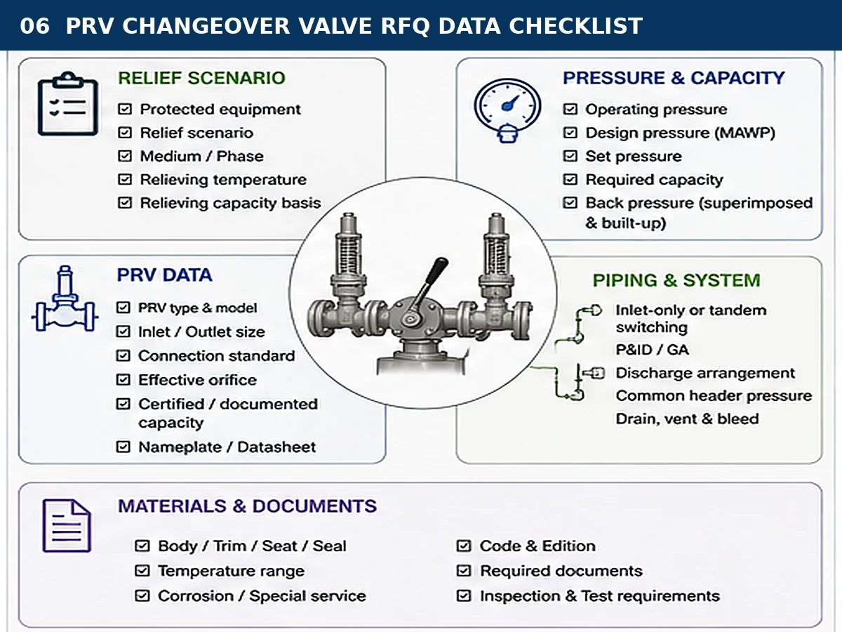
The checklist supports preliminary review and does not replace project sizing or code verification.
Process and relief data
- Protected equipment and governing scenario
- Medium, composition and phase
- Operating pressure and MAWP/design pressure
- Set pressure and required capacity
- Relieving pressure and temperature
- Capacity calculation basis
PRV data
- PRV type, model and manufacturer when replacing
- Effective orifice
- Inlet and outlet connections
- Certified or documented capacity
- Materials and seat type
- Datasheets and nameplate photographs
Selector and piping data
- Duty/standby or parallel philosophy
- Inlet-only or tandem switching
- P&ID, GA and piping sketch
- Superimposed and built-up back pressure
- Drain, vent and bleed requirements
- Retrofit dimensions and access space
Materials and documents
- Body, trim, seat, seal and packing requirements
- Pressure class or PN and temperature range
- Locking and position indication
- Applicable code and adopted edition
- Inspection, test and witness requirements
- Material and dimensional documents
Technical references and limitations
This guide explains engineering decision logic and RFQ translation. It does not reproduce copyrighted code clauses and does not establish certification for any specific ZOBAI model.
- API 520 Part I official information — API identifies the 10th Edition as published; use it for sizing and selection scope within its stated application.
- API 521 official information — supports relief-system design, overpressure causes, relieving rates and disposal-system review; verify the edition adopted for the project.
- ASME BPVC Section XIII official page — ASME lists the 2025 Edition for overpressure-protection devices, capacity or flow-resistance certification, installation and system design.
- ISO 4126-1 official page — ISO 4126-1:2013 remains current after confirmation in 2025 and covers safety-valve product scope and terminology.
Verify the edition adopted by the owner, contract and jurisdiction. A currently published edition is not automatically the governing edition for an existing installation or project.
Frequently asked questions
Can two PRVs on a changeover valve provide double relieving capacity?
Not automatically. In a normal duty/standby arrangement, only one PRV is connected to the protected equipment, so the active PRV generally must handle its assigned relief case independently. Combined capacity requires a separately engineered parallel or staged arrangement.
Does the changeover valve need the same connection size as the PRVs?
The connections must be mechanically compatible, but matching size does not prove sufficient internal flow area or acceptable pressure loss. Confirm the exact selector bore, port geometry and manufacturer resistance data.
Can both PRVs be isolated during switching?
The design and approved operating sequence should maintain an available pressure-relief path. Verify the internal porting, mechanical stops, linkage and intermediate positions of the selected changeover valve.
When is an outlet changeover valve required?
It depends on the discharge arrangement. A common closed header, inactive-branch exposure, back pressure or coordinated isolation requirement may justify tandem inlet and outlet switching. Separate open discharges may require a different arrangement.
Does a changeover system solve back-pressure problems?
No. Superimposed and built-up back pressure must still be calculated and checked against the PRV configuration, selector resistance and discharge piping.
Can an existing selector be replaced by matching flange size and dimensions?
No. Also confirm the relief basis, internal flow path, pressure-temperature rating, materials, operating direction, locking method, discharge configuration and PRV capacity.
What information is needed for a PRV changeover valve quotation?
Provide the protected equipment, relief scenario, medium and phase, operating and design pressures, set pressure, required capacity, relieving temperature, back pressure, PRV data, selector arrangement, P&ID, connections, materials, switching controls, documents and applicable code.
Send your PRV changeover system data for engineering review
Submit the protected equipment, relief scenario, pressure and capacity basis, relieving temperature, back pressure, PRV datasheets, selector arrangement, P&ID, material requirements and required documents.
Ask a safety valve engineer