ASME B31.8 Gas Pipeline Relief and Pressure Protection Guide
Understand how ASME BPVC, ASME B31 piping codes, ASME B16.5 flange ratings and ASME certification marks are commonly used when specifying safety valves and pressure relief valves. This guide is written for procurement, EPC, maintenance and plant engineering teams that need to identify the right code reference, documentation package and RFQ data before selecting a valve.
- Current ASME listing: B31.8-2025 for gas transmission and distribution piping systems.
- Start with the MAOP or allowable pressure of each protected downstream segment and item of station equipment.
- Relief capacity must be based on the maximum credible inflow or source capacity, not on nominal line size alone.
- Venting, noise, dispersion, ignition risk, back pressure and local pipeline regulations remain part of the final design.
Use B31.8 for the gas pipeline system context—not as a standalone valve-sizing formula
Important engineering limitation
Where pressure-relief and pressure-limiting devices are reviewed
Transmission Pipelines
Compressor Stations
Metering & Regulating Stations
Gas Storage & Closed-Pipe Facilities
Gas Mains & Service Lines
Separators, Filters & Heaters
Set pressure and capacity must protect the lowest-rated downstream boundary
Pressure-boundary checklist
- Upstream design pressure and maximum source pressure
- Downstream MAOP or design pressure
- Regulator set points, monitor arrangement and lock-up behavior
- Bypass and manual-valve operating cases
- Pressure drop between sensing point and protected boundary
- Set pressure and allowable accumulation or overpressure
- Outlet back pressure and vent or header pressure
- Pressure-temperature rating of valve and connections
Define the event before calculating required relief capacity
Regulator Failure
Monitor or Bypass Failure
Blocked Outlet
Compressor Upset
External Heat or Fire
Thermal Expansion & Trapped Gas
Relief capacity is based on the maximum credible source flow
Capacity inputs
- Maximum upstream pressure and minimum downstream pressure
- Regulator or valve flow coefficient and failure position
- Compressor maximum flow or connected source capacity
- Gas composition, molecular weight and compressibility
- Relieving temperature and pressure
- Allowable overpressure or accumulation
- Superimposed and built-up back pressure
- Simultaneous station relief assumptions
- Certified gas capacity and selected orifice
- Vent stack or disposal-system capacity
Choose the device from operating margin, gas cleanliness, capacity and discharge conditions
Conventional Spring-Loaded
Balanced Bellows
Pilot-Operated
Pressure-Limiting or Control Device
Soft Seat vs Metal Seat
Flanged vs Threaded Connection
Gas relief must be routed to a safe location and included in the valve calculation
Discharge review checklist
- Atmospheric, closed vent, flare or recovery destination
- Vent-stack height and outlet orientation
- Normal and upset downstream pressure
- Built-up back pressure at governing flow
- Noise and high-velocity gas discharge
- Gas dispersion and ignition-source separation
- Sour gas, wet gas or condensate handling
- Reaction force and independent pipe support
- Drainage and prevention of liquid pockets
- Local environmental and pipeline regulatory requirements
A practical B31.8 gas pipeline relief review
Confirm code and jurisdiction
Map pressure boundaries
Define credible failures
Calculate required capacity
Select device architecture
Review discharge system
Verify materials and connections
Complete records and RFQ
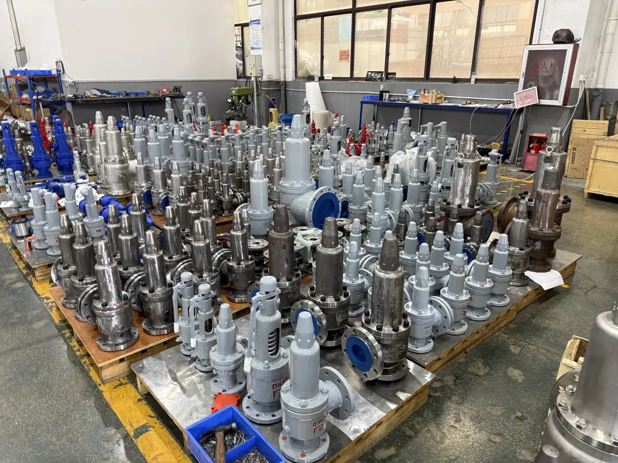
From Code Requirement to Shop-Floor Verification
Standards define technical requirements, but purchase-order compliance depends on design, materials, inspection scope and recorded test results. This actual ZOBAI photograph documents workshop inventory of assembled safety valves. It is facility evidence, not a substitute for project-specific certificates or an agreed inspection and test plan.
Information needed for a B31.8 gas pipeline relief quotation
Recommended engineering input
- Pipeline or station type and location
- ASME B31.8 edition and local jurisdiction
- Upstream pressure and downstream MAOP
- Regulator, monitor, bypass or compressor data
- Governing overpressure scenario
- Gas composition and relieving temperature
- Required relieving rate or source-capacity calculation
- Back pressure and vent or flare arrangement
- Valve size, connection, class and materials
- Seat leakage, noise and emissions requirements
- Datasheet, P&ID, station drawing and piping layout
- Required calibration, test, material and inspection records
Continue the gas pipeline pressure-protection review
Natural Gas Safety Valves
Pipeline Safety Valves
Compressor Safety Valves
High Back Pressure Service
ASME Safety Valve Standards
API 520 Safety Valve Sizing
Common questions about ASME B31.8 gas pipeline relief
ASME B31.8 covers gas transmission and distribution piping systems, including pipelines, compressor stations, metering and regulating stations, gas mains, service lines and related pipeline facilities within its stated scope.
No. It establishes the gas pipeline code context and pressure-system requirements. The relief device still requires a defined overpressure scenario, capacity calculation, certified valve data and compliance with the project sizing and product standards.
The protection system should prevent each downstream piping segment and connected item from exceeding its allowable pressure under credible failures such as regulator failure, bypass operation or compressor upset.