
ASME B31.12 Hydrogen Piping and Pressure-Relief Guide
ASME B31.12 provides requirements for piping and pipelines handling gaseous hydrogen, gaseous hydrogen mixtures and piping in liquid-hydrogen service. It addresses the hydrogen-specific material, design, fabrication, inspection, testing, operation and maintenance issues that must be resolved before a pressure-relief device is selected.
This guide connects the B31.12 piping boundary to practical safety-valve work: defining the protected section, identifying regulator, compressor, blocked-in and thermal relief cases, checking hydrogen compatibility and leakage, reviewing safe venting and preparing a complete PSV or PRV RFQ.
- Current published edition: ASME B31.12-2023.
- Scope includes gaseous hydrogen, gaseous hydrogen mixtures and piping in liquid-hydrogen service.
- The Code applies through the piping joint connected to associated vessels and equipment, but not to the vessels or equipment themselves.
- Pressure-relief selection still requires a separate governing load, certified valve capacity and safe discharge review.
B31.12 separates general requirements, industrial piping and pipelines
Edition and application note
Hydrogen changes the material, leakage and ignition review
Hydrogen-Assisted Material Degradation
Small-Molecule Leakage
Wide Flammability and Low Ignition Energy
High Pressure and Rapid Expansion
Pressure and Thermal Cycling
Cryogenic Liquid Hydrogen
Typical B31.12 hydrogen piping and pressure boundaries
Electrolyzer Outlet Piping
Hydrogen Compressor Systems
High-Pressure Storage and Manifolds
Pressure-Reducing Stations
Refueling Stations and Tube-Trailer Interfaces
Hydrogen Pipelines
Fuel-Cell Supply Systems
Liquid-Hydrogen Piping
The governing relief case must be defined before the valve is sized
Regulator or Control-Valve Failure
Compressor Blocked Discharge
Blocked Outlet or Closed Isolation
Thermal Expansion of Trapped Fluid
Vaporizer or Heat-Exchanger Failure
External Heat or Fire
Hydrogen compatibility must be verified for the actual pressure and duty cycle
Material and design checklist
- Hydrogen concentration and gas purity
- Maximum and minimum design temperature
- Design pressure and pressure cycles
- Pipe, fitting, flange and valve material
- Weld procedure and heat-treatment condition
- Fatigue and fracture assessment where required
- Hardness and material-test requirements
- PMI and heat-number traceability
- Gasket, seal and elastomer compatibility
- Corrosion allowance and external environment
A hydrogen relief valve must satisfy capacity, leakage and operating requirements
Hydrogen valve review points
- Required relieving rate and certified gas capacity
- Set pressure and operating-pressure margin
- Conventional, balanced bellows or pilot design
- Seat construction and leakage requirement
- Body, trim, spring, bellows and seal materials
- Back pressure and vent-header pressure
- Inlet pressure loss and dynamic stability
- Connection standard and pressure class
- Cleaning and contamination control
- Calibration, pressure and seat-test reports
Hydrogen discharge must be routed to a defined safe location
Discharge-system checklist
- Atmospheric vent, flare or recovery destination
- Vent outlet elevation and safe separation
- Normal and maximum header pressure
- Simultaneous relief assumptions
- Dispersion and ignition-source review
- Outlet piping support and reaction force
- Drainage and prevention of liquid accumulation
- Low-temperature discharge and icing where applicable
- Electrical area and earthing requirements
- Inspection access and weather protection
Eight-step B31.12 hydrogen pressure-protection workflow
Define the B31.12 boundary
Identify protected sections
Define credible relief cases
Calculate the governing load
Verify materials and design
Select the relief device
Review venting and installation
Complete the document package
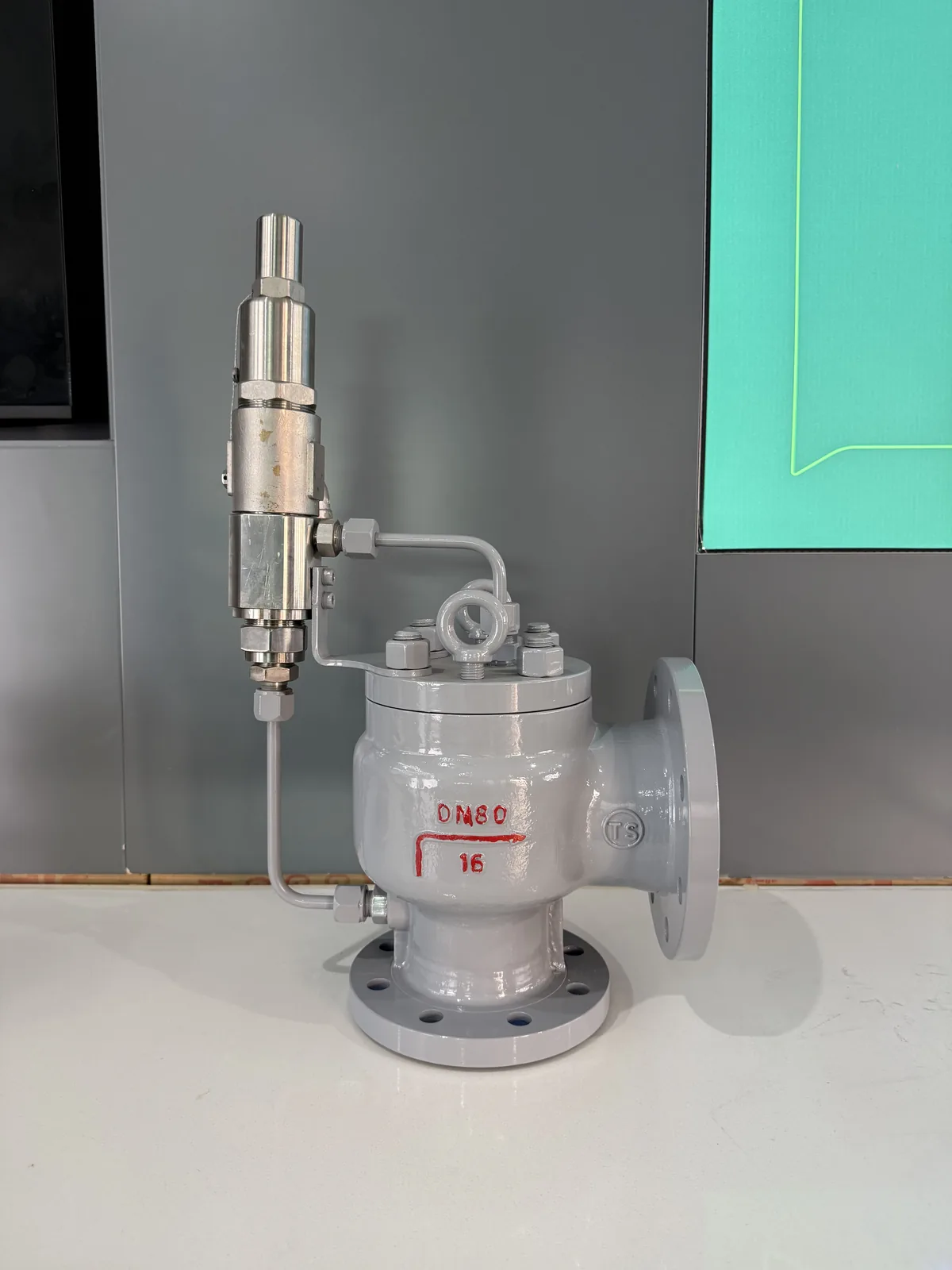
From Code Requirement to Shop-Floor Verification
Standards define technical requirements, but purchase-order compliance depends on design, materials, inspection scope and recorded test results. This actual ZOBAI photograph documents stainless steel pilot-operated safety relief valve on display. It is facility evidence, not a substitute for project-specific certificates or an agreed inspection and test plan.
Information needed for a B31.12 hydrogen safety-valve review
Recommended engineering input
- Applicable ASME B31.12 section and edition
- P&ID, piping boundary and protected equipment
- Hydrogen composition, purity and phase
- MAWP, design pressure and set pressure
- Operating and relieving temperature
- Governing scenario and required relieving rate
- Compressor, regulator or upstream source data
- Back pressure and discharge destination
- Piping, flange, valve and seal materials
- Required calculations, certificates and test reports
Continue the hydrogen piping and pressure-relief review
Hydrogen Safety Valves
High-Pressure Safety Valves
Pipeline Safety Valves
Pressure-Temperature Ratings
ASME B16.5 Flanges
Ask an Engineer
Common questions about ASME B31.12 hydrogen piping
ASME B31.12 provides requirements for the design, materials, fabrication, inspection, testing, operation and maintenance of hydrogen piping and pipeline systems.
The current published edition is ASME B31.12-2023. Projects should confirm the required edition with the jurisdiction, owner and project specification.
Yes. Its scope includes piping in liquid-hydrogen service. Gaseous-hydrogen pipelines are also covered, while the exact code section depends on the system.
The piping code applies through the joint connecting the piping to associated vessels and equipment, but it does not provide the construction rules for the vessels or equipment themselves.
Common cases include regulator or control-valve failure, compressor blocked discharge, blocked outlet, trapped-liquid thermal expansion, vaporizer failure and external heat exposure where applicable.
Not automatically. The selected valve must be verified for hydrogen-compatible materials, leakage requirement, set pressure, certified gas capacity, operating margin, back pressure, seals, connections and discharge conditions.
Provide the B31.12 section, protected piping, hydrogen composition and phase, design and set pressures, temperature, governing relief case, required capacity, back pressure, materials, connections and required test documents.