Understand safety valve outlet reaction force, open vs closed discharge, piping load paths, support and nozzle loads, and the inputs needed for stress review.

A safety valve outlet reaction force is the flow-induced mechanical load created during a relief event. It is an important input to discharge-piping design, but it is not automatically the load on a pipe support, the valve connection, or a connected equipment nozzle.
The engineering sequence is broader:
Define the relief condition → identify the discharge boundary → calculate the applicable reaction force → trace the actual piping load path → verify supports, nozzle loads, and any required stress or dynamic checks.
A common failure point is not the reaction-force calculation itself, but what happens next: the force is calculated for one boundary and then applied to the installed piping as though it were already the final support or nozzle load.
What Does Safety Valve Outlet Reaction Force Actually Represent?
When relieving fluid leaves a safety valve or its discharge system,
changes in fluid momentum and pressure at the discharge boundary can
create a mechanical reaction. In open compressible discharge, commonly
used engineering methods account for both momentum and pressure-thrust
effects. This treatment is documented in the
Emerson Pressure Relief Valve Engineering Handbook.
The important boundary is what that calculation tells you. A
discharge reaction force is a load input associated
with the relieving flow. It does not, by itself, establish:
- the reaction at a particular pipe support;
- the force or moment transmitted into the valve connection;
- the allowable load of that valve connection;
- the load on a vessel, header, or equipment nozzle; or
- the combined stress state of the discharge piping.
Those quantities depend on the installed piping geometry and its
restraints. A statement such as “the valve produces X force, so the
nearest support must resist X” is therefore incomplete. The calculated
reaction has to be placed into the mechanical model of the real
discharge piping before support and nozzle loads can be judged.
For broader inlet, drainage, orientation, and discharge-routing
requirements, see the
Safety Valve Installation Guide
.
This page remains focused on reaction force and its mechanical
interpretation.
What Inputs Determine the Outlet Reaction Force?
Do not start with the nominal valve outlet size. Start with the
relief duty and actual discharge condition.
Different fluid states require different engineering treatment.
The Emerson Pressure Relief Valve Engineering Handbook presents separate
approaches for gas or vapor, steam, non-flashing liquid, and two-phase
flow rather than one universal reaction-force equation.
| Input | Why it matters |
|---|---|
| Relieving mass flow | Determines the momentum associated with the discharge. |
| Fluid and phase state |
Determines which calculation method and assumptions are applicable. |
| Relieving or discharge temperature | Enters the applicable thermodynamic treatment. |
| Relevant fluid properties |
Gas/vapor, liquid, and two-phase methods require different properties. |
| Outlet or discharge area |
Defines part of the discharge boundary used in the force calculation. |
| Outlet pressure | Pressure thrust may contribute to the reaction. |
| Ambient or downstream pressure | Defines the pressure boundary against which the discharge occurs. |
| Open or connected discharge arrangement |
Determines whether an atmospheric-discharge approach is applicable. |
| Actual downstream geometry |
Becomes necessary when converting the local force into a piping-load problem. |
The practical implication is simple: two valves with the same outlet
connection can have different reaction loads if their relieving flow,
fluid state, pressure boundary, or discharge arrangement differs.
Phase assumptions need particular care. A method developed for gas or
vapor should not be applied to liquid discharge simply because the
connection size is the same. Likewise, a liquid method that assumes
non-flashing service is not automatically valid for flashing liquid,
and a homogeneous two-phase model remains conditional on its stated
assumptions.
If the required relieving rate itself has not yet been established,
complete that work first. The
Safety Valve Sizing and Certified Relieving Capacity Guide
owns that task; this article treats relieving flow as an input to the
mechanical review.
Why Open and Closed Discharge Systems Need Different Treatment
Before choosing a reaction-force calculation, determine
where the safety valve discharges.
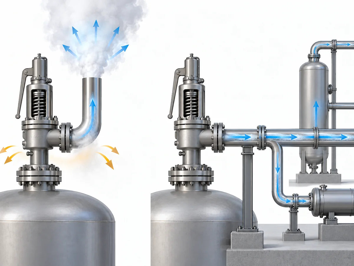
An open discharge releases fluid through a defined termination to
atmosphere. A closed discharge remains connected to downstream piping,
a header, or another disposal system. That difference changes the
calculation boundary.
API 520 Part II
is the relevant API installation authority family, while manufacturer
engineering guidance such as the
LESER Engineering Handbook installation chapter
illustrates the open/closed-system distinction and its limitations.
| Open / atmospheric discharge | Closed / connected discharge |
|---|---|
| A terminal discharge boundary can usually be identified. | Downstream piping remains part of the pressure/flow system. |
| Open-discharge reaction methods may be applicable. |
An open-discharge formula should not be transplanted automatically. |
|
Momentum and pressure effects can be evaluated at the termination. |
Pressure, velocity, geometry, and transient behavior may interact through the connected system. |
| A local reaction vector can often be defined. |
System-level forces may depend on expansions, bends, restraints, and downstream conditions. |
Under an established steady-flow condition, forces within some closed
systems can partially balance. That does not justify
the blanket conclusion that a closed relief system has no mechanically
significant reaction load.
Changes in section, direction, downstream pressure, and transient flow
can still matter. The defensible rule is:
Define the discharge boundary before selecting the calculation method.
Back pressure belongs nearby in the engineering logic, but it is not
synonymous with reaction force. Back pressure describes the outlet
pressure condition affecting the relief system; reaction/support
analysis asks how the resulting fluid and pressure behavior loads the
mechanical system.
For detailed superimposed and built-up back-pressure discussion, use
the dedicated
Back Pressure and Bellows
guide.
When Is a Steady Reaction Force Not Enough?
A steady-state reaction calculation answers a specific question:
what reaction is associated with the established relieving flow?
It does not necessarily answer:
what is the complete mechanical load history while the valve opens
and the discharge system responds?
During opening, pressure and flow change with time. A published study
on safety-valve blowdown by Muschelknautz and Wellenhofer reported
short-duration reaction-force peaks during the opening process in the
configurations they studied. That supports treating steady and transient
loading as related but distinct engineering questions rather than
assuming that one steady value describes the entire event.
See the
Wiley study on flow reaction forces during safety-valve blowdown.
A transient or dynamic review becomes more relevant when, for example:
-
the valve opening event is rapid compared with the response of the
piping system; -
pressure waves or unsteady flow in connected discharge piping may
affect the mechanical response; - the system is sensitive to short-duration loads; or
- the governing project/code basis requires a dynamic treatment.
This is a screening boundary, not a claim that every safety valve needs
a time-history analysis. The opposite shortcut is also unsafe: a single
steady-state force should not automatically be treated as the complete
event load.
The method must follow the piping code, edition, and project basis that
actually govern the installation.
ASME B31.1,
for example, is a Power Piping code and should not be treated as a
universal substitute for a different governing piping code. This
article therefore does not publish a universal dynamic load multiplier.
How Does Outlet Piping Geometry Change the Load Path?
Once the reaction force has been calculated, the next engineering
question is:
where does that load go in the installed piping?
Geometry controls much of that answer. Emerson Birkett technical
guidance notes that an unsupported discharge pipe can act as a lever,
so the mechanical load applied to the valve depends on both the
discharge reaction and the piping geometry. That is why pipe length,
direction changes, and restraint locations matter after the local
reaction force has been established.
See the
Emerson Birkett safety-relief-valve technical data.
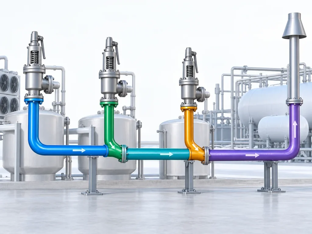
Direction changes add another layer. At an elbow, the fluid momentum
changes direction, so the discharge system must be considered as a set
of force vectors, moment arms, supports, and boundary conditions rather
than as one scalar force traveling unchanged down the pipe.
Relieving flow → reaction vector → piping geometry → direction
changes and moment arms → restraints → valve/support/equipment loads.
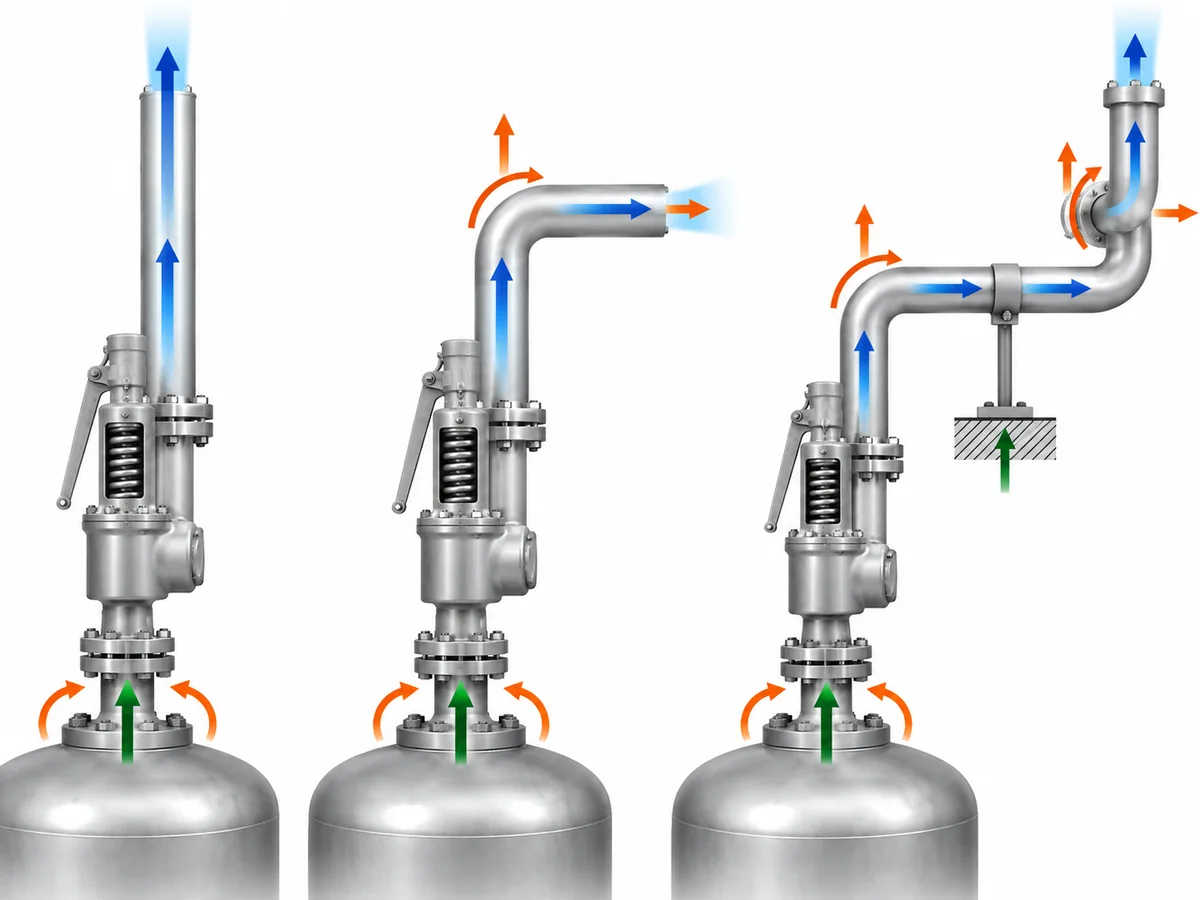
An offset, elbow, vent stack, silencer, reducer, or connection into
downstream piping can alter the load path. The exact consequence depends
on the actual geometry and restraints.
Supports also do more than carry weight. A guide, anchor, line stop, or
other restraint changes the mechanical boundary condition of the piping
system. Do not turn that into a fixed support-spacing rule: the suitable
arrangement depends on the actual piping geometry, restraint model, and
allowable loads.
The relief reaction is also only one load case. Depending on the
project, the installed system may have to accommodate dead weight,
thermal movement, pressure-related loading, discharge reaction, and
applicable transient or occasional loads.
A layout that works for weight does not automatically work for relief
loading. Conversely, adding excessive restraint simply to resist thrust
can create other mechanical consequences when the piping expands
thermally.
Why Reaction Force Is Not the Same as the Final Support or Nozzle Load
The reaction-force calculation and the final mechanical acceptance
check are separate engineering milestones.
| Quantity | What it represents | What controls it |
|---|---|---|
| Discharge reaction force | Flow-induced load associated with the relief event. |
Relief flow, phase/state, pressure boundary, outlet condition, and applicable calculation method. |
| Load at the valve connection | Force and moment transmitted between valve and connected piping. |
Reaction force, geometry, moment arms, restraints, and other piping loads. |
| Support reaction | Load carried by a particular support or restraint. |
Complete piping geometry, stiffness, restraints, and applicable load cases. |
| Equipment/nozzle load |
Load transferred to a vessel, header, or other equipment connection. |
Mechanical response of the connected system. |
| Pipe-stress result | Combined piping response. |
Pressure, weight, thermal, relief-event, and other project-defined load cases. |
The difference becomes clearer with a simple thought experiment.
Assume two systems have the same calculated discharge reaction. One has
a short, well-defined outlet route with a nearby engineered restraint.
The other has a longer offset before the piping is supported.
The flow reaction can be the same while the bending moment and loads
transmitted into the valve or supports are different.
This is why
allowable loads cannot be inferred from the reaction-force equation
.
A valve-nozzle allowable, vessel-nozzle allowable, support capacity, or
equipment allowable must come from the documentation applicable to the
actual valve, equipment, structure, or project.
Values from another manufacturer’s valve or another installation are
not substitutes. No model-specific ZOBAI allowable outlet/nozzle load
is established by this article, so none should be inferred from the
generic engineering discussion.
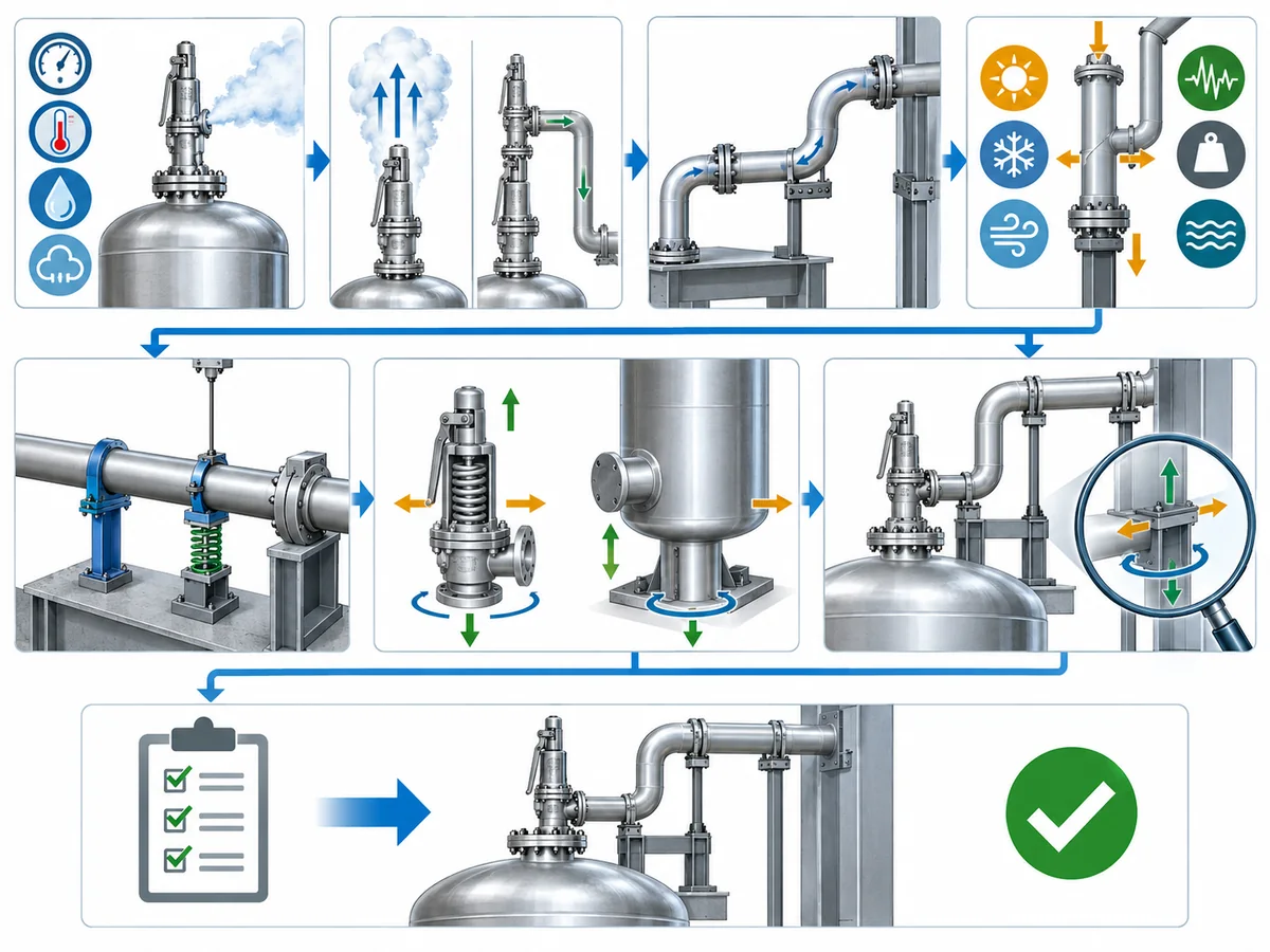
What Should Be Verified Before the Outlet Piping Support Arrangement Is Accepted?
The ten checks below are a practical engineering review
framework for this article. They are not presented as a
universal API or ASME mandated sequence. The governing project code,
equipment documentation, and piping/stress design basis remain the
authority for an actual installation.
-
Establish the relief duty.
Confirm the governing relief case and required relieving-flow basis.
If the required flow is still unknown, the mechanical reaction
calculation is premature. -
Establish the fluid and phase state.
Identify whether the relieving stream is gas/vapor, steam,
non-flashing liquid, or a case requiring two-phase treatment. -
Define the discharge boundary.
Confirm whether the valve discharges openly to atmosphere or into
connected downstream piping. For a connected system, also establish
the relevant downstream pressure and routing information. -
Use a reaction-force method that matches that boundary.
Keep the result tied to its calculation boundary instead of
immediately treating it as the load at a support. -
Map the real outlet geometry.
Record the valve outlet orientation, straight pipe lengths, elbows,
offsets, reducers or expansions where relevant, silencers or other
inline items where present, and connection to any vent, header, or
disposal system. -
Define the restraints.
Identify the actual supports, guides, anchors, line stops, structural
attachments, and other boundary conditions relevant to the piping
analysis. -
Include the other applicable load cases.
Determine which additional loads have to be considered under the
project’s design basis, including weight, thermal movement, pressure
effects, and any applicable occasional or dynamic case. -
Obtain the real allowable loads.
Use valve-, equipment-, support-, and project-specific documentation.
If a decision-critical nozzle or structural allowable is missing, the
mechanical acceptance is not complete. -
Decide whether the steady calculation is sufficient.
Confirm whether the installed configuration and governing design
basis require any additional transient or dynamic assessment. -
Close the piping/stress review.
For an actual project, the relief duty, calculation boundary, piping
layout, restraints, applicable load cases, and relevant allowable
loads need to be resolved before the mechanical acceptance can be
closed.
The useful project handoff is therefore not simply
“reaction force = ___.” It is:
relief duty + fluid state + discharge boundary + reaction-force basis
+ actual geometry + restraint model + applicable allowable loads +
dynamic-review status.
That package allows process/relief and piping/stress disciplines to work
from the same design basis.
Preparing a safety valve RFQ or outlet-system review?
Send the known relief case, fluid and phase, required relieving rate,
pressure and temperature conditions, back pressure or discharge route,
and applicable project requirements through
Ask a Safety Valve Engineer
.
ZOBAI can use confirmed valve/application inputs for the valve review;
final piping-support and stress acceptance remains dependent on the
installed project system.
A safety-valve reaction-force calculation is neither “just a formula” nor the final support design. It is the bridge between the relief calculation and the mechanical review of the installed discharge system.
Calculate the correct reaction for the correct discharge case, then verify how the actual piping carries it.