
Thermal Relief Valves for Blocked-In Liquid Lines, Heat Exchangers and Process Piping
Thermal relief valves protect isolated liquid sections from rapid pressure rise caused by ambient heat, heat tracing, hot process fluid, steam, thermal oil, solar exposure or equipment warm-up. Use this page to prepare RFQ data for blocked-in liquid relief, water and glycol loops, LNG transfer lines, thermal oil skids, heat exchangers and compact process packages.
››› Thermal Relief Overview
Thermal relief looks small, but the pressure rise can be fast
Important Engineering Note
››› Thermal Relief Applications
Where thermal relief valves are commonly required
01
Blocked-In Liquid Lines
02
Heat Exchangers & Jackets
03
Water & Glycol Loops
04
LNG & Cryogenic Lines
05
Thermal Oil Skids
06
Pump, Filter & Skid Piping
››› Relief Case Analysis
Thermal relief selection starts with the trapped volume and heat source
01
Ambient Temperature Rise
02
Heat Tracing or Insulation
03
Hot Utility or Process Side
04
Pump Deadhead / Blocked Outlet
05
Cryogenic Heat Leak
06
Maintenance Isolation
››› RFQ Data Checklist
What to prepare before asking for a thermal relief valve quotation
- Protected equipment, piping section, line size and pressure rating.
- Liquid type, density or composition, viscosity if relevant, and phase condition.
- Trapped volume or pipe length between isolation points.
- Minimum and maximum temperature, heat tracing or heat source condition.
- Design pressure, MAWP, set pressure and allowable accumulation basis.
- Discharge destination: safe drain, return tank, expansion vessel, flare, BOG header or closed collection.
- Back pressure, downstream isolation risk and whether discharge path remains open.
- Material, connection, seat tightness, certificate and testing requirements.
››› Service Data Matrix
Thermal relief valve data matrix
Water / Glycol Loop
Thermal Oil System
LNG Transfer Line
Heat Exchanger Section
Pump / Filter Skid
Loading / Transfer Line
››› Selection Framework
How to specify a thermal relief valve correctly
- Confirm protected pressure boundary and weakest design pressure.
- Define trapped volume and whether any section can be isolated.
- Use the credible maximum temperature or heat input case.
- Check liquid expansion, relieving capacity and phase behavior.
- Review valve configuration, material, seat and connection standard.
- Confirm that discharge routing and back pressure are acceptable.
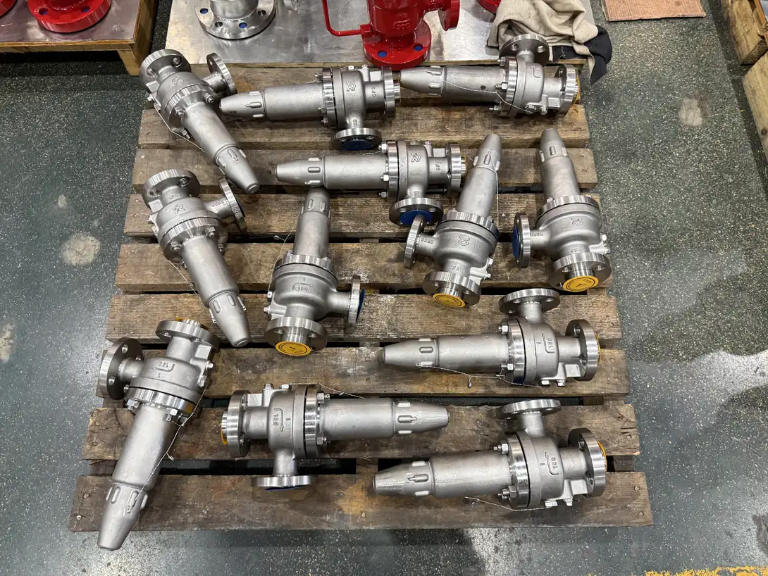
Real Production Evidence for Application Review
For Thermal Relief Valves | Blocked-In Liquid Protection | ZOBAI service, supplier review should connect valve construction to set pressure, medium, temperature, capacity, back pressure and the governing code. This actual ZOBAI photograph documents compact stainless steel relief valves on a pallet. Review it with drawings, material records and pressure-test documents.
››› Installation & Discharge
Thermal relief depends on an available discharge path
Field installation checks
- Install close to the trapped liquid section with short, clear inlet path.
- Avoid isolation valves that can block the relief path unless locked/open and controlled by procedure.
- Route discharge to safe drain, collection, return or approved vent system.
- Check freezing, plugging, fouling, corrosion and leakage management.
- Confirm set pressure and material compatibility before commissioning.
››› Standards & Documents
Documents to confirm before ordering
Technical Datasheet
Sizing / Capacity Basis
Trapped volume, temperature rise, liquid expansion, governing relief case and required relieving capacity.
Test & Certificate Package
››› Minimum RFQ Data
Thermal relief RFQ checklist
Protected equipment
Line size / trapped volume
Liquid / phase
Design pressure / MAWP
Set pressure
Temperature range
Heat source
Required capacity
Back pressure
Discharge route
Material / seat
Documents
››› Selection Errors
Common thermal relief valve selection mistakes
Selecting only by pipe size
Pipe size confirms mechanical fit, but the valve must also match set pressure, liquid relief capacity, material, seat tightness, back pressure and discharge route.
Missing small trapped volumes
Small trapped volumes can still produce rapid pressure rise when heated. Every isolated liquid section should be checked, especially around check valves, heat exchangers, filters and maintenance bypasses.
Blocking the discharge path
A relief valve cannot protect the system if its discharge route is isolated, plugged, frozen, undersized or routed to an unsafe location.
Ignoring flashing or cryogenic behavior
LNG, LPG, hot water and some solvents can flash during relief. Discharge routing, material and capacity review should consider phase change.
Treating thermal relief as a generic accessory
Thermal relief is part of the pressure protection system. It should be documented, tagged, tested and maintained according to project requirements.
››› Related Engineering Resources
Continue your thermal relief valve selection review
Safety Valve Selection Guide
Safety Valve Sizing
Water Service Safety Valves
LNG Safety Valves
Heat Exchanger Safety Valves
Ask an Engineer
››› FAQ
Thermal relief valve FAQ
When is a thermal relief valve needed?
A thermal relief valve should be reviewed when liquid can be trapped between closed valves or equipment boundaries and later heated by ambient temperature, heat tracing, hot process fluid, steam, thermal oil, solar exposure or warm-up cycles.
Is thermal relief sizing always small?
The required flow is often small compared with fire or pump relief, but the pressure rise can be rapid. Sizing should still be confirmed from trapped volume, liquid expansion, temperature rise, set pressure and discharge conditions.
Can I use a standard relief valve for thermal relief?
Not automatically. The valve should match the liquid service, set pressure, material, seat tightness, connection, back pressure and discharge route. Cryogenic, corrosive or high-temperature service may require special material or design review.
What data should I send for a thermal relief RFQ?
Send protected equipment, line size, trapped volume, liquid, temperature range, design pressure, set pressure, heat source, discharge route, back pressure, material requirement, connection and documents required.
Where should thermal relief discharge go?
Discharge may go to a safe drain, closed collection, return tank, expansion tank, BOG header, flare, vent or other approved safe destination depending on the fluid and project relief philosophy.
Why can blocked-in LNG require special review?
LNG can build pressure as heat leaks into an isolated line and may flash during relief. Cryogenic material, cold discharge, icing, seat tightness and safe venting should be reviewed together.