Natural Gas Safety Valves for Pipelines, Compressor Stations, PRV Stations and Fuel Gas Systems
Natural Gas Safety Valves for Pipelines, Compressor Stations, PRV Stations and Fuel Gas Systems
Natural gas safety valves protect transmission pipelines, distribution stations, compressor packages, gas receivers, separators, filter vessels, metering skids, pressure reducing stations, fuel gas systems, gas storage equipment, heater skids, dehydration units and gas processing packages from overpressure. Correct selection starts with gas composition, molecular weight, set pressure, protected equipment MAWP, maximum operating pressure, required relieving capacity, blocked outlet case, compressor discharge case, regulator failed-open case, fire case, back pressure, discharge destination, leakage tightness, material compatibility, low-temperature condition, sour gas content and required test documents.
Where Natural Gas Safety Valves Are Used
Natural gas relief service is common across upstream, midstream, downstream and industrial fuel gas systems. The right valve depends on whether the protected system is a pipeline, compressor package, pressure reducing station, separator, fuel gas skid or gas storage unit.
Gas Transmission and Distribution Pipelines
Used on pipeline stations, city gate stations, district regulating stations, line heaters, metering runs and downstream headers. Selection should review MAOP, regulator failure, blocked outlet, gas composition, vent stack height and downstream pressure boundary.
Natural Gas Compressor Stations
Used on compressor discharge lines, interstage separators, gas receivers, knockout drums, lube oil/gas packages and recycle systems. Relief review should include compressor map, blocked discharge, recycle failure, pulsation, vibration and discharge routing.
Pressure Reducing and Metering Stations
Used downstream of pressure regulators, slam-shut valves, control valves and metering skids. The key scenario is often regulator failed open, where downstream equipment must be protected from higher upstream source pressure.
Gas Separators, Filters and Dehydration Units
Used on inlet separators, filter separators, coalescers, glycol contactors, molecular sieve vessels and dehydration packages. Selection should review blocked gas outlet, fire case, liquid carryover, sour gas, wet gas and flare back pressure.
Fuel Gas and Burner Supply Systems
Used on fuel gas conditioning skids, heater fuel systems, turbine fuel gas packages, boiler gas trains and industrial burner supply lines. Relief review should include regulator failure, low-pressure downstream piping, vent location and leakage tightness.
CNG, Gas Storage and Skid Packages
Used on CNG storage banks, buffer vessels, tube trailers, gas charging skids, pressure letdown skids and modular gas packages. Selection should review high pressure, temperature change, isolation, vent dispersion, seat tightness and inspection access.
Natural Gas Safety Valve Selection Starts With the Credible Pressure Source
Natural gas systems are often protected from high upstream pressure, compressor energy, blocked discharge, fire exposure, control failure or thermal expansion. The valve must be sized from the governing relief scenario, not from normal gas demand only.
Pressure Regulator Failed Open
When a regulator fails open, high-pressure upstream gas can flow into a lower-rated downstream header. The downstream safety valve should be sized from failed-open flow, upstream pressure, regulator capacity and downstream design pressure.
Compressor Blocked Discharge
Gas compressors can overpressure receivers, discharge lines and interstage equipment if discharge is blocked or recycle fails. Selection should review compressor map, maximum flow, discharge temperature, pulsation and vent or flare back pressure.
Blocked Outlet on Separator or Filter Vessel
Separators, filters and dehydration vessels can be overpressured by upstream flow when the outlet is blocked. Relief capacity should be based on maximum credible inlet flow and pressure source, not normal vessel throughput only.
External Fire Exposure
Gas receivers, separators, storage vessels and condensate-containing equipment may require fire-case relief review. Fire case can involve vapor expansion, liquid vaporization and simultaneous relief into a shared flare or vent system.
Thermal Expansion of Blocked-In Gas or Condensate
Isolated gas sections, condensate pockets or liquid-filled lines can increase pressure when heated. Thermal relief is especially important on blocked-in liquid hydrocarbon, condensate or glycol sections connected to natural gas systems.
Back Pressure From Flare or Closed Vent Systems
Natural gas relief often discharges to vent stacks, flare headers, closed vents or recovery systems. Superimposed and built-up back pressure can affect valve capacity, opening behavior and reseating.
Natural Gas Safety Valve Application Cases with Typical RFQ Data
These cases show how natural gas safety valve requirements are commonly described before model selection. Final sizing must be confirmed by gas composition, protected equipment datasheet, pressure source, relief calculation, back pressure review and project standard.
Case 1: Downstream Safety Valve for Natural Gas PRV Station
Regulator Failed OpenPRV station safety valves should be sized from the failed-open case. Normal downstream gas demand is usually not enough to confirm protection.
Case 2: Compressor Discharge Safety Valve
Compressor ProtectionCompressor discharge relief is often a high-flow gas case. Valve stability, vibration and discharge system capacity should be reviewed together.
Case 3: Gas Filter Separator Safety Valve
Separator / Filter VesselFilter separators may contain wet gas and condensate. Material, fouling risk and discharge handling should be reviewed before selecting a standard gas valve.
Case 4: Fuel Gas Skid Safety Valve
Industrial Fuel GasFuel gas skids often have compact layouts and operators nearby. Vent routing and leakage control are as important as pressure capacity.
Case 5: CNG Storage Bank Safety Valve
High Pressure GasCNG service requires high-pressure gas review, tight shutoff and safe venting. Small leakage can become a flammable gas hazard.
Case 6: Sour Natural Gas Separator PSV
Sour Gas / H₂SSour natural gas service requires material and documentation review in addition to normal gas sizing. Toxic discharge should be routed to a controlled system.
Natural Gas Safety Valve Data Matrix
| Natural Gas Service | Typical Medium | Common Relief Cause | Required Engineering Check | Recommended Valve Review | Risk if Missed |
|---|---|---|---|---|---|
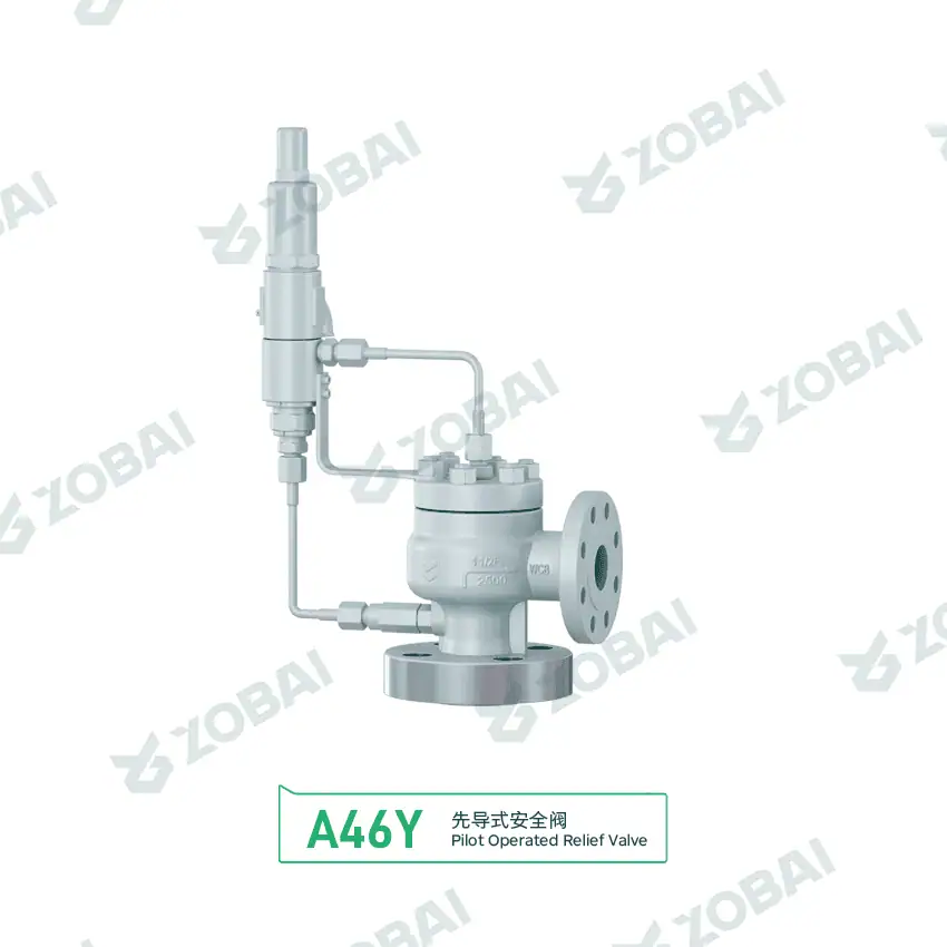
| Pressure reducing station | Dry gas, odorized gas, fuel gas | Regulator failed open, bypass leakage, downstream blockage | Upstream pressure, failed-open flow, downstream MAOP, vent back pressure and noise | Gas PSV or pilot operated safety valve where clean service allows | Downstream overpressure, nuisance relief or unsafe venting |
| Compressor discharge | Natural gas, methane-rich gas, fuel gas, hydrogen blend | Blocked discharge, recycle failure, compressor control failure | Compressor map, molecular weight, discharge temperature, pulsation and vibration | High-capacity gas PSV or pilot operated valve | Receiver overpressure, chatter, leakage or outlet pipe damage |
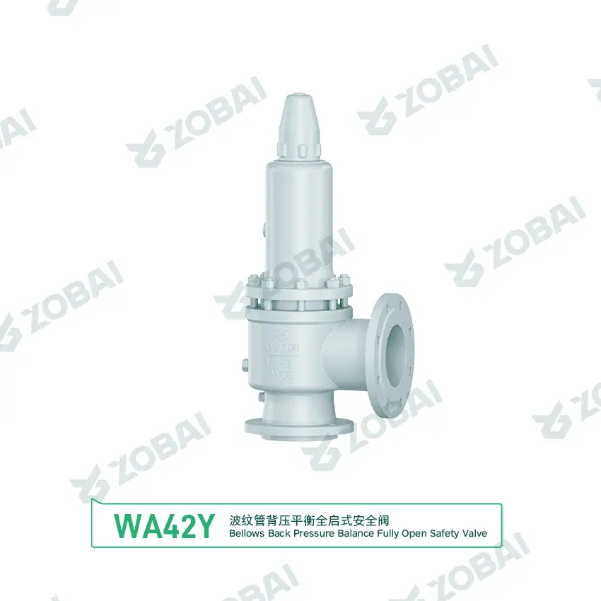
| Gas separator / filter vessel | Wet gas, dry gas, condensate carryover, water vapor | Blocked outlet, fire case, upstream pressure surge | Vessel MAWP, maximum gas flow, liquid carryover, fouling and material compatibility | Spring-loaded PSV, bellows PSV or sour service PSV depending on conditions | Undersized relief, fouled valve or unsafe discharge |
| Fuel gas skid | Natural gas, fuel gas, odorized gas | Regulator failure, blocked burner header, control failure | Downstream design pressure, regulator Cv, vent location and leakage tightness | Compact gas safety valve or pilot valve for clean service | Burner train overpressure, gas leakage or operator exposure |
| CNG / high pressure gas storage | Compressed natural gas | Overfill, compressor failure, thermal expansion, fire exposure | Storage pressure, temperature rise, high-pressure rating, vent dispersion and noise | High-pressure gas safety valve with tight shutoff and certified capacity | High-energy release, noise hazard or flammable gas cloud |
| Sour natural gas | Natural gas with H₂S, CO₂, water and condensate | Blocked outlet, fire case, pressure control failure | H₂S, CO₂, pH, chlorides, hardness, wet/dry condition and toxic discharge route | Sour service PSV with material and hardness documentation | Cracking failure, toxic release or project document rejection |
How to Specify a Natural Gas Safety Valve Correctly
1. Confirm protected equipment and pressure boundary
Start with pipeline MAOP, vessel MAWP, skid piping design pressure, compressor receiver rating or downstream header pressure limit. The set pressure should protect the lowest-rated credible pressure boundary.
2. Define gas composition and molecular weight
Natural gas composition affects molecular weight, compressibility, relief capacity, flammability, sour service risk and material selection. Provide methane, ethane, propane, nitrogen, CO₂, H₂S and water content where available.
3. Size from the governing relief case
Review regulator failed open, compressor blocked discharge, separator blocked outlet, fire case, control valve failure and thermal expansion. The highest credible relieving flow controls valve capacity.
4. Review back pressure and discharge destination
Discharge may go to atmosphere, vent stack, flare header, closed vent or recovery system. Back pressure can affect valve capacity, opening, blowdown and reseating, especially in closed relief systems.
5. Select valve type for leakage and operating margin
Clean gas with high operating pressure margin may suit pilot operated valves. Conventional or spring-loaded valves may suit standard systems. Soft seat, metal seat, leakage class and maintenance requirements should be defined early.
6. Confirm material and low-temperature requirements
High pressure letdown can cool gas during relief. Low ambient temperature, Joule-Thomson cooling, sour gas, wet gas and CO₂ content may require low-temperature material, sour service review or special trim selection.
Natural Gas Safety Valves Must Be Reviewed With Venting, Noise, Back Pressure and Gas Dispersion
Why natural gas relief installation controls real safety
Natural gas safety valve performance depends on the full relief path. A correctly sized valve can still create risk if the vent stack is too short, the outlet points toward operators, the flare header creates excessive back pressure, the inlet branch is undersized, or the valve discharges near ignition sources, air intakes or enclosed areas.
Installation should review inlet pressure loss, valve orientation, outlet support, acoustic vibration, vent stack height, gas dispersion, safe distance from ignition sources, closed header back pressure, flare capacity, drain and liquid pocket removal, low-temperature cooling, snow or ice formation, inspection access and whether the valve can be isolated only under approved procedures.
Field installation checks
- Confirm set pressure, MAOP / MAWP and protected equipment tag before installation.
- Keep inlet pressure loss within the project design limit.
- Route natural gas discharge to an approved vent stack, flare, closed vent or recovery system.
- Check outlet back pressure from flare, vent stack, silencer or closed relief header.
- Keep discharge away from platforms, air intakes, doors, ignition sources and enclosed spaces.
- Support outlet piping for reaction force, vibration and thermal movement.
- Provide access for calibration, seat tightness testing, inspection and valve replacement.
Standards and Documents to Confirm Before Ordering
Common natural gas relief references
Natural gas safety valve specifications may reference ASME, API, ISO, EN, GB, local gas pipeline rules, owner pipeline standards, compressor package specifications and project relief philosophy. The applicable design basis should be confirmed before quotation.
- ASME B31.8 for gas transmission and distribution piping systems where specified by the project.
- API 520 for pressure-relieving device sizing and selection reference where required.
- API 521 for pressure-relieving and depressuring system review, including flare, fire case and system-level relief cases.
- ASME BPVC Section VIII where gas receivers, separators, filters or storage vessels are pressure vessels.
- ASME B31.3 where gas processing plant piping, skid piping or fuel gas process piping is specified.
- API 526 when flanged steel pressure relief valve dimensions and pressure classes are specified.
- API 527 when seat tightness testing is required by project specification.
- NACE MR0175 / ISO 15156 where sour natural gas or H₂S-containing environments are specified.
Typical natural gas valve document package
Documentation should be agreed before manufacturing, especially for pipeline stations, compressor packages, PRV stations, gas processing units, sour gas systems, CNG skids and EPC export projects.
- Technical datasheet with tag number, model, size, orifice, set pressure and connection.
- Sizing calculation or certified gas relieving capacity confirmation.
- Gas composition, molecular weight, compressibility basis and relieving temperature data.
- Set pressure calibration certificate, pressure test report and seat tightness test report.
- Material certificate for body, bonnet, nozzle, disc, trim, spring and pressure-retaining parts.
- Sour service, hardness, PMI or low-temperature material documents where specified.
- General arrangement drawing with dimensions, weight, outlet orientation and maintenance clearance.
- Nameplate, tag list, spare parts list, inspection witness record and packing record when required.
Official Standards Sources for Natural Gas Relief Valve Review
Use ZOBAI internal pages for application guidance, RFQ preparation and product selection. Use the official publisher pages below when project specifications require gas transmission, pressure vessel, process piping, relief sizing, depressuring, flanged valve or sour service standard identification.
Natural Gas Safety Valve RFQ Data Checklist
| Required Data | Why It Matters | Example Input |
|---|---|---|
| Protected equipment | Defines pressure boundary, code basis and set pressure limit. | Pipeline header, compressor receiver, filter separator, PRV station, fuel gas skid, CNG storage |
| MAOP / MAWP / design pressure | Defines the maximum pressure the valve must protect. | 6 barg, 16 barg, 42 barg, 100 barg, Class 300, pipeline MAOP value |
| Set pressure | Defines valve opening pressure and capacity basis. | Downstream protection set point, vessel MAWP-based set pressure, compressor discharge set pressure |
| Gas composition | Affects molecular weight, capacity, material, sour service and flammability review. | Methane-rich gas, fuel gas, odorized gas, wet gas, H₂S, CO₂, nitrogen, hydrogen blend |
| Relief scenario | Determines required capacity and valve type. | Regulator failed open, compressor blocked discharge, blocked outlet, fire case, control failure |
| Required capacity | Confirms whether the valve can protect the system. | kg/h, Nm³/h, SCFM, MMSCFD, regulator failed-open flow, compressor map |
| Operating pressure range | Shows operating margin and leakage risk. | Normal pressure, maximum operating pressure, pressure fluctuation range |
| Relieving temperature | Controls material, low-temperature review and capacity. | Ambient, low ambient, compressor discharge temperature, post-letdown cold gas temperature |
| Back pressure and discharge route | Influences capacity, stability, noise and safe venting. | Atmospheric vent, flare header, closed vent, recovery line, high vent stack |
| Installation condition | Affects orientation, piping loads, maintenance access and discharge safety. | Outdoor station, compact skid, compressor package, pipeline yard, offshore module |
| Material and seat requirement | Prevents leakage, corrosion, sour service failure and document rejection. | Carbon steel, stainless trim, soft seat, metal seat, low-temperature material, sour service material |
| Required documents | Avoids inspection, FAT, shipment and commissioning delays. | Datasheet, drawing, MTC, sizing report, calibration report, pressure test, seat tightness test |
Final selection must be confirmed by gas composition, protected equipment datasheet, pressure source, relief scenario, required capacity, applicable standard, back pressure calculation, discharge philosophy, certified valve capacity and engineering review.
Common Natural Gas Safety Valve Selection Mistakes
Using normal gas demand as relief flow
Regulator failed-open flow or compressor blocked-discharge flow can be much larger than normal consumption. The valve should be sized from the governing upset case.
Ignoring back pressure from flare or closed vent
Back pressure can reduce capacity or change valve behavior. It should be reviewed before choosing conventional, bellows or pilot operated design.
Missing leakage tightness requirements
Natural gas leakage can create flammable gas hazards and emissions. Seat type, leakage test and operating pressure margin should be defined clearly.
Forgetting sour gas material review
Natural gas containing H₂S, CO₂ or water may require sour service material, hardness control and additional documentation.
Discharging gas near unsafe areas
Vent discharge should avoid platforms, air intakes, doors, ignition sources and enclosed spaces. Gas dispersion and wind direction should be reviewed.
Ignoring low-temperature relief conditions
High-pressure gas letdown can cool during relief. Low ambient temperature and Joule-Thomson cooling can require low-temperature material review.
Continue Your Natural Gas Safety Valve Selection Review
These related pages help move from natural gas relief requirements to detailed valve selection, sizing, high-pressure service, compressor protection, high back pressure review and complete RFQ preparation.
Natural Gas Safety Valve FAQ
Prepare a Complete Natural Gas Safety Valve Datasheet Before Quotation
Send the protected equipment datasheet, MAOP or MAWP, design pressure, set pressure, gas composition, molecular weight, relief scenario, required capacity, operating pressure range, relieving temperature, back pressure, discharge route, installation condition, material requirement, seat requirement, connection standard and required documents. A complete datasheet helps confirm correct gas sizing, valve stability, leakage control and safe flammable gas discharge.