Share your medium, set pressure, temperature, size, standard, or datasheet, and our team will review your requirement and respond with the appropriate next step.
What Is a Sanitary Safety Valve? Hygienic Design Guide
A sanitary safety valve is an automatic pressure-relieving device designed for hygienic or aseptic process systems. It protects tanks, vessels, clean-steam lines, bioprocess skids and sanitary pipelines from overpressure while using product-contact geometry, connections, materials, seals and surface conditions that can be cleaned, drained and documented for the intended service. A polished body or tri-clamp …
A sanitary safety valve is an automatic pressure-relieving device designed for hygienic or aseptic process systems. It protects tanks, vessels, clean-steam lines, bioprocess skids and sanitary pipelines from overpressure while using product-contact geometry, connections, materials, seals and surface conditions that can be cleaned, drained and documented for the intended service. A polished body or tri-clamp connection does not by itself make a valve sanitary.
The valve still has to satisfy the complete pressure-protection duty: the set pressure must be consistent with the protected equipment and applicable code arrangement; the required relieving capacity must be established from a credible overpressure scenario; the selected valve must provide sufficient certified or manufacturer-documented capacity; and inlet pressure loss, outlet back pressure, materials, installation and safe discharge must be acceptable. Hygienic design adds another layer: product retention, dead spaces, drainability, surface finish, ferrule and gasket geometry, CIP/SIP exposure, clean-steam condensate, elastomer documentation and cleaning validation.
Quick Answer / Engineering Summary: A sanitary safety valve combines overpressure protection with hygienic design. It should open at the specified condition, pass the required relief load, remain stable, reseat without unacceptable leakage and avoid becoming an uncleanable or poorly drained point in the process. Pressure-performance evidence and hygienic-design evidence are separate and both are required.
Approval boundary: A sanitary connection, 316L body, polished exterior or generic hygienic declaration does not prove set-pressure accuracy, certified capacity, code acceptance, CIP/SIP compatibility or installed-system stability.
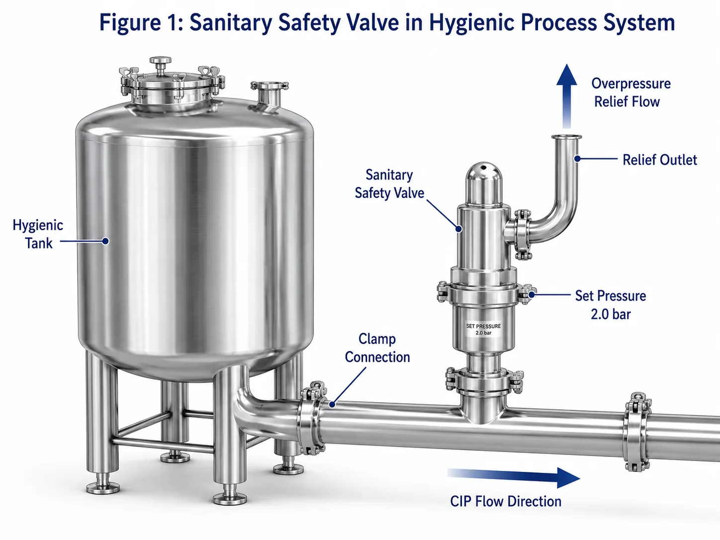
A sanitary safety valve must satisfy both the overpressure-protection duty and the hygienic design requirements of the installed process.
What Is a Sanitary Safety Valve?
A sanitary safety valve is a reclosing pressure-relief valve intended for systems where product purity, cleanability or aseptic control is required in addition to mechanical pressure protection. Typical services include food and beverage production, dairy processing, fermentation, pharmaceutical manufacturing, bioprocessing, clean steam and high-purity utilities.
In practical engineering, the valve must satisfy two independent approval questions:
Pressure protection: Does the valve open at the approved set pressure and provide sufficient documented capacity under the actual fluid, temperature and back-pressure conditions?
Hygienic suitability: Can the product-contact path be effectively cleaned, drained, inspected and maintained without unacceptable retention, crevices, material degradation or undocumented elastomers?
Sanitary Safety Valve Definition
When inlet pressure reaches the specified opening condition, the valve opens and creates a relief path. Flow must increase enough to control the governing overpressure case. After the source of overpressure is removed and pressure falls through the valve’s blowdown range, the valve should reseat and remain acceptably tight.
The term sanitary describes the product-contact design, materials, surface condition, cleanability, drainability and documentation. It does not replace the pressure-relief requirements that apply to any safety valve.
Sanitary Safety Valve vs Standard Safety Valve
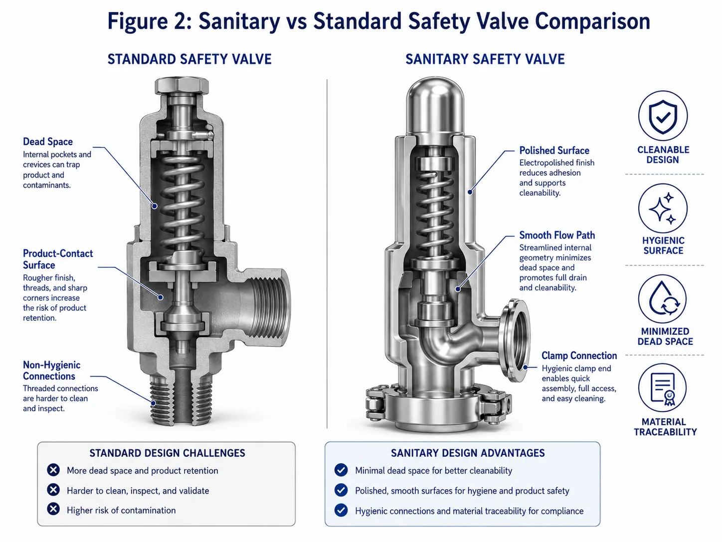
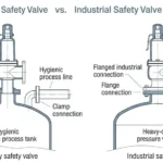
A standard industrial safety valve may be acceptable for general steam, gas or liquid service but unsuitable for direct product contact. Internal pockets, threaded cavities, rough or undocumented surfaces, non-drainable geometry, exposed springs or incompatible gaskets can create contamination and cleaning risks even when the pressure rating is correct.
Evidence
What It Supports
What It Does Not Prove
Set-pressure certificate
Opening adjustment under the stated test conditions
Required capacity, hygienic design or field stability
Capacity certificate or documented flow data
Relieving performance for a defined valve and basis
Cleanability, seal compatibility or correct relief scenario
Material and surface-finish records
Specified product-contact materials and surface condition
Pressure-relief capacity or installation suitability
Hygienic certificate or declaration
Defined hygienic scope for the stated model or component
Blanket coverage of every size, seal, option or code marking
Sanitary Safety Valve vs Sanitary Relief Valve
Manufacturers and industries do not always use sanitary safety valve and sanitary relief valve consistently. In common process terminology, a safety valve is often associated with rapid opening in compressible service, while a relief valve is often associated with proportional liquid service. Hygienic product families may use broader wording.
The approved datasheet should therefore state the full function, medium and phase, opening characteristic, set pressure, required capacity, valve construction and certification basis. Use the pressure relief valve definition guide and the PRV vs PSV terminology guide when project wording is unclear.
How Does a Sanitary Safety Valve Work?
The basic sequence is the same as for other automatic reclosing pressure-relief devices: the valve stays closed during normal operation, responds when inlet pressure reaches the specified opening condition, develops lift, discharges the required flow and closes after pressure falls. Hygienic design changes how the product-contact path, seals, drainability and cleaning functions must be executed.
Set Pressure and Automatic Opening
Set pressure determines the specified opening response under the applicable test definition. It should be established from the protected equipment’s MAWP or allowable pressure limit, the code arrangement, normal operating pressure, pressure fluctuation and any multiple-device arrangement. It must not be raised simply to stop leakage.
Pressure Term
Engineering Meaning
Sanitary-System Consequence
Operating pressure
Normal pressure while the valve should remain closed
Insufficient margin can cause simmer, product or clean-steam loss and repeated seat contamination
Set pressure
Specified opening condition under defined testing
Controls when protection begins; it does not establish capacity
Overpressure
Pressure increase above set pressure during relief
Influences available lift and capacity
Accumulation
Pressure increase above the equipment MAWP or allowable boundary
Defines the equipment-side pressure limit for the approved case
Blowdown
Difference between set and reseating pressure
Affects cycling, process recovery and post-lift leakage
The required relieving capacity comes from the governing credible scenario. In sanitary systems this may include blocked outlet, clean-steam regulator failure, external heat input, thermal expansion of trapped liquid, pump deadhead, sterilization pressure rise, gas blanketing failure, fermentation gas generation or high-to-low pressure leakage through equipment.
Required capacity is the flow demand from the engineering analysis. Certified or manufacturer-documented capacity is the supported performance of the selected valve and configuration. Clamp size is neither of these. A valve can fit the ferrule and open at the correct set pressure while remaining hydraulically undersized.
After pressure falls, the disc should return squarely to a clean, undamaged seat. Leakage after a lift can result from product deposits, crystallized cleaning chemicals, elastomer damage, thermal distortion, condensate, chatter, guide friction, poor assembly or operating pressure too close to set pressure.
Seat-tightness testing verifies leakage under a stated method and condition. It does not prove relieving capacity, hygienic cleanability or installed-system stability. Where API 527 seat-tightness testing is specified for an applicable valve, its scope should be separated from the hygienic leakage, sterility and cleaning-validation expectations of the process.
Why Hygienic Design Changes the Valve Requirements
A pressure-relief valve can perform mechanically and still fail the hygienic requirement. Product retained behind a gasket, in a non-drainable inlet branch or around an inaccessible seat may survive the cleaning cycle. A soft seat may remain tight during production but swell, harden or lose compression after repeated hot-caustic or SIP exposure.
The valve must therefore be evaluated as part of the hygienic system, including cleaning flow paths, orientation, ferrule and gasket alignment, outlet drainage, access for inspection and the effect of any lifting or pneumatic test device.
Where Are Sanitary Safety Valves Used?
Sanitary safety valves are used where a pressurized hygienic system requires automatic overpressure protection without compromising cleanability, product integrity or validation. The correct design depends on whether the valve contacts product, clean utility, cleaning solution, steam, gas or a mixture of phases.
Application
Typical Overpressure or Hygiene Concern
Engineering Review Point
Food and beverage processing
Blocked flow, gas blanketing, cleaning residue and food-contact materials
Required capacity, hygienic connection, contact materials and cleaning coverage
Dairy systems
CIP cycles, protein or fat retention and temperature changes
Dead space, drainability, surface condition and seal resistance
Fermentation systems
Gas generation, foam carryover and biological deposits
Relief load, foam behavior, outlet routing and cleanability
Pharmaceutical and bioprocessing
Purity, bioburden, batch traceability and SIP exposure
ASME BPE/project requirements, material heat traceability and elastomer documentation
Clean steam systems
Steam capacity, condensate, thermal cycling and seat leakage
Steam performance, drainage, seat construction and safe discharge
Hygienic skids and tanks
Compact routing, short nozzles, common outlets and maintenance access
Inlet loss, back pressure, orientation, cleanability and removal envelope
Food and Beverage Processing
Applications include process tanks, pasteurizers, carbonated-product systems, gas-blanketed vessels and hygienic utilities. The valve should not introduce an uncleanable cavity or discharge product into an unsafe or contamination-prone location.
Dairy and Fermentation Systems
Dairy residues and fermentation foam can contaminate the seat, guide or discharge route. The relief scenario should account for gas generation or blocked flow, while the hygienic review should address CIP coverage, foam carryover, gasket interfaces and complete drainage after cleaning.
Pharmaceutical and Bioprocessing Systems
These services may require controlled surface-finish records, material heat numbers, weld documentation, elastomer declarations, passivation or electropolishing evidence and defined cleaning validation. A generic “sanitary” certificate should not be accepted without checking the exact model, size, seal option and manufacturing scope.
Clean Steam and Clean Utility Systems
Clean steam creates high temperature, condensate and thermal-cycling demands. The valve should have a supported steam-capacity basis, suitable seat and trim materials, effective drainage, safe discharge and an inspection strategy for seat damage after lift or repeated sterilization cycles.
Hygienic Tanks, Skids and Process Lines
Compact equipment often encourages long inlet branches, adapters or outlet elbows that fit physically but create inlet loss, trapped liquid, back pressure or poor access. Final skid design should be reviewed with the actual valve envelope, removal path, cleaning circuit and discharge loads.
Sanitary Safety Valve vs Standard Safety Valve
The difference should be evaluated from both the pressure-protection and hygienic perspectives. A sanitary valve is not simply a smaller industrial valve with a clamp adapter.
Selection Factor
Sanitary Safety Valve
Standard Industrial Safety Valve
Primary duty
Pressure protection plus hygienic or aseptic suitability
Pressure protection and mechanical service suitability
Connection
Hygienic ferrule, aseptic connection or other cleanable interface
Flanged, threaded, welded or industrial connection
Product-contact geometry
Reviewed for retention, crevices, cleaning access and drainage
May include cavities not suitable for product contact
Surface condition
Specified finish, treatment and documentation for contact surfaces
Chosen mainly for corrosion, wear and pressure service
Seals
Formulation and documentation reviewed for product, CIP and SIP
Selected mainly for process fluid and temperature
Documentation
May include material heat traceability, elastomer, finish, passivation and hygienic scope
Typically focuses on pressure, material, calibration and capacity evidence
Failure consequence
Under-protection, contamination, retained product, failed cleaning or validation delay
Under-protection, leakage or mechanical reliability problems
Sanitary suitability depends on internal geometry, contact materials, seals, cleaning and documentation—not on the connection style alone.
Product-Contact Surface Design
Contact surfaces should avoid cracks, exposed threads, uncontrolled crevices and inaccessible pockets. The review should include the nozzle, disc, seat, ferrule, gasket interface, inlet branch and any lift-device penetration that can contact product or cleaning solution.
Dead Space and Cleanability
Dead space is a combined component-and-installation issue. A well-designed valve can still be installed on a long branch that receives inadequate cleaning velocity or cannot drain. Do not apply one generic dead-leg ratio without confirming the governing standard, geometry and project definition.
Sanitary Connections
Clamp assemblies require compatible ferrules, gasket geometry, alignment and controlled tightening. Gasket intrusion can restrict the inlet or create a retention point, while misalignment can produce a ledge that is difficult to clean. Connection interchangeability should therefore be confirmed dimensionally and hygienically.
Material and Seal Compatibility
Compatibility must cover production fluid, cleaning chemicals, steam, temperature cycles and expected service life. The polymer family name alone is not enough because different EPDM, FKM and PTFE-based formulations can have different additives, temperature performance, extractables and compliance evidence.
Documentation and Traceability
The purchase specification should define which pressure-performance and hygienic records are required and how they connect to the supplied serial number. A sample certificate or brochure is not an order-specific traceability package.
Key Hygienic Design Requirements
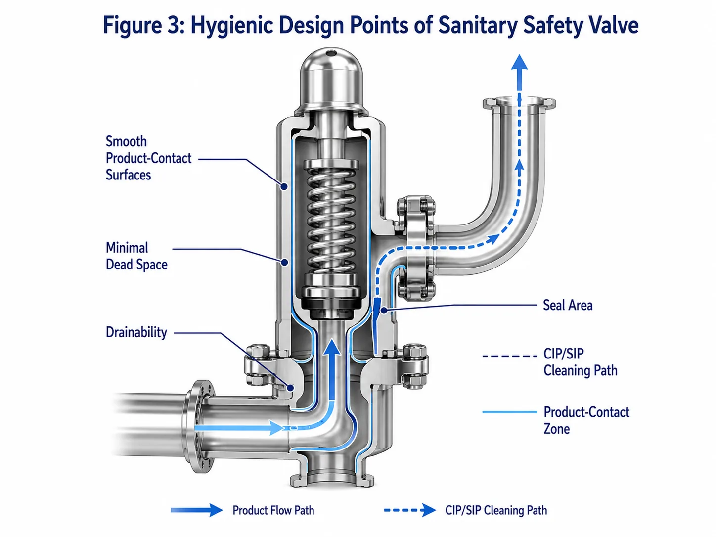
Hygienic design should reduce retained product, permit effective cleaning and sterilization, support drainage and allow inspection. The review must cover the valve and the adjoining process connection as one hygienic entity.
Hygienic Requirement
Why It Matters
Evidence or Review
Controlled product-contact surface condition
Reduces retention and supports reproducible cleaning
Specified finish, measurement method and location, polishing and treatment records
Minimal retention volume
Reduces stagnant product and cleaning shadow
Internal drawing, seat/ferrule geometry and installation review
Drainability
Reduces condensate, product and chemical retention
Installed orientation, slopes, low points and outlet arrangement
CIP/SIP compatibility
Prevents premature seal and surface deterioration
Actual chemical, concentration, time, temperature, pressure and cycle frequency
Cleanable sealing interface
Prevents residue around elastomers and hidden cavities
Seal-groove design, gasket fit, removal and inspection procedure
Maintainability
Supports controlled reassembly and validated return to service
Access, spare-part traceability, torque procedure, calibration and cleaning instructions
The valve and its inlet and outlet arrangement should be assessed together for cleaning coverage, retention and drainage.
Smooth Product-Contact Surfaces
A specified roughness value should include the applicable surface, measurement method and acceptance basis. Mechanical polish and electropolish are not interchangeable descriptions. Welds, ferrules, transitions and repaired areas can govern cleanability even when the main body finish is acceptable.
Minimal Dead Legs and Product Entrapment
The inlet should be as direct as practical while meeting pressure-relief installation requirements. Long branches can retain product and can also create excessive pressure loss during relief. Hygienic and hydraulic design therefore point in the same direction: avoid unnecessary restriction and stagnant volume.
CIP and SIP Cleanability
CIP/SIP conditions are design inputs. State the chemicals, concentration range, peak temperature, contact time, steam quality where relevant, cycle frequency and rinse conditions. Cleaning coverage should be demonstrated for the actual valve orientation and process path; a material compatibility chart alone is insufficient.
Drainability and Installation Orientation
Drainability should be checked in the installed position, including the seat pocket, inlet ferrule, body cavity, outlet, bonnet vent and any pneumatic-lift chamber. Retained clean-steam condensate can corrode, cool the seat unevenly or create water hammer and unstable discharge.
Hygienic Lift Device or Pneumatic Lift Option
A lift device may support cleaning or functional checks only when its operation is approved for the valve and process. It does not replace set-pressure calibration, capacity evidence or the required seat-tightness test. The device itself must not create an uncleanable penetration, uncontrolled exhaust path or contamination route.
Key Engineering Parameters for Selection
Hygienic design cannot compensate for an incorrectly sized or unstable safety valve. Selection should begin with the protected equipment and overpressure case, then integrate pressure performance and sanitary requirements.
Protected Equipment and MAWP
Identify the tank, vessel, clean-steam generator, pipeline or skid and distinguish MAWP, design pressure and normal operating pressure. The approved set pressure and allowable accumulation depend on the equipment code and relief-device arrangement. A sanitary component rating cannot be assumed to be the equipment MAWP.
Set Pressure and Operating Pressure Margin
Operating too close to set pressure can cause simmer and seat wear. In hygienic service, repeated micro-lift can also draw product or cleaning residue across the seat and create a persistent leakage and cleaning problem. There is no single operating-margin percentage for every sanitary valve; use manufacturer data and the actual pressure stability.
Required Relieving Capacity
Calculate or approve the governing relief load before asking the supplier to finalize a valve. For fermentation, gas generation and foaming may matter. For clean steam, regulator failure or blocked outlet may govern. For trapped liquid, thermal expansion may require a small but specific relief path.
Certified Capacity and Orifice Area
The selected effective flow area and supported capacity must meet the required load under the approved pressure, temperature, phase and back-pressure basis. The same clamp size can contain different nozzles and lifts. A hygienic certificate never substitutes for capacity evidence.
Medium, Temperature and Cleaning Cycle
Specify the process medium and its relieving phase, not only the normal product name. Include foam, solids, viscosity, vaporization, fermentation gas, entrained liquid, cleaning solution and clean-steam exposure where relevant. The most severe seal condition may occur during cleaning rather than production.
Back Pressure and Discharge Path
A closed hygienic recovery line, common steam header, condensate-filled outlet or downstream filter can create superimposed or built-up back pressure. This can affect lift, effective capacity, blowdown and reseating. Outlet routing should be safe, drainable and cleanable without imposing excessive load on the valve.
Conventional designs may be sensitive to back pressure; exposed cavities and cleanability must be reviewed
Balanced bellows
Reduces certain outlet-pressure force effects
Bellows material, fatigue, cleaning exposure and bonnet venting require control
Pilot-operated
Can provide tight shutoff and selected high-pressure performance
Small passages, seals, sensing lines and exhaust paths may be vulnerable to product, condensate or cleaning residue
Material and Seal Selection for Sanitary Safety Valves
Material selection should cover every pressure-containing, product-contact, guiding and sealing component. Body material alone does not determine corrosion resistance, cleanability or service life.
Item
Review Point
Risk if Ignored
Body, nozzle and disc
Grade, heat traceability, corrosion, erosion and finish
Pitting, seat damage, contamination and early leakage
Guide and spindle
Galling resistance, deposits, alignment and cleaning exposure
Sticking, off-center reseating and unstable lift
Spring and bonnet
Temperature, environment and separation from product
Set-pressure drift, corrosion and maintenance difficulty
Bellows or diaphragm
Material, fatigue, pressure, cleaning chemical and temperature
Loss of balance, leakage or hidden process release
EPDM / FKM / other elastomer
Exact formulation, product, CIP/SIP and compliance evidence
Swelling, hardening, compression set, extractables or leakage
PTFE-based seat or seal
Grade, creep, sealing load, temperature and chemical duty
Cold flow, poor recovery or unstable tightness
316L Stainless Steel and Product-Contact Parts
316L is widely used but is not universally resistant to every chloride, acid, cleaning chemical or temperature. Confirm the exact grade, heat number, fabrication route, weld treatment, surface condition and corrosion mechanism. Nozzle and disc materials can govern seat life even when the body is acceptable.
Surface Finish and Electropolishing
The RFQ should distinguish mechanical finish, electropolishing, passivation and weld finishing. State which product-contact surfaces are included and how compliance is measured. A certificate that reports one sample reading does not automatically prove every internal contact area.
EPDM, PTFE, FKM and Other Seal Materials
Select seals using supplier data for the exact compound. Review steam resistance, chemical swelling, compression set, decompression, friction, extractables and required food-contact or pharmaceutical documentation. Material families should not be approved solely from a generic compatibility table.
Steam, CIP Chemicals and SIP Temperature Limits
Repeated exposure can be more damaging than one short peak. Record maximum and normal temperature, heating and cooling rate, cycle frequency, chemical concentration and contact time. The maintenance plan should reflect actual cycle severity and previous as-found condition.
Material Certificates and Elastomer Compliance
Define whether the project requires order-specific metallic material certificates, elastomer batch declarations, food-contact status, USP-related evidence, surface-finish records or extractables information. “FDA compliant” or “USP compliant” is incomplete unless the supplier identifies the exact material, intended use, conditions and applicable regulatory or compendial basis.
Sanitary and pressure-protection standards have different scopes. A project may require several of them, but they should not be presented as interchangeable certificates.
Authorized repair of pressure relief valves where the owner, jurisdiction or NBIC route requires it
VR addresses repair authorization; it is not a hygienic design certification
Edition and scope control: The official ASME page currently lists ASME BPE 2026, while the ASME BPVC pressure-equipment route uses the edition adopted by the project or jurisdiction. The RFQ should state the required edition for every cited standard. A supplier declaration should identify the exact model, size, seal option, manufacturing entity and certificate scope rather than claiming broad compliance.
ASME BPE for Bioprocessing and Hygienic Equipment
Use ASME BPE when the project adopts its high-hygiene requirements. The purchase specification should identify the applicable edition and the exact design, material, surface, inspection and documentation requirements rather than claiming broad “BPE compliance.”
3-A Sanitary Standards for Hygienic Equipment Design
3-A documents are equipment- and system-specific. Confirm whether an applicable sanitary standard or accepted practice covers the component and whether a valid symbol authorization is required. A supplier logo or reference to general 3-A principles is not equivalent to an authorization for the quoted valve.
EHEDG Guidelines for Hygienic and Aseptic Valves
EHEDG Guideline 14 is directly relevant to valve design in hygienic and aseptic processes. It supports the review of cleanability and product safety, while the pressure-protection performance must still be established separately.
ASME Section VIII / National Board Where Pressure Protection Certification Is Required
When a sanitary valve protects an ASME pressure vessel, confirm the required equipment code, Section XIII rules, code marking, certified capacity and manufacturer or assembler scope. After repair, verify whether a National Board VR-authorized route is required before recalibration, sealing and return to service.
FDA / USP / Food Contact Requirements for Seals and Product-Contact Materials
Food-contact and pharmaceutical evidence should be requested against the exact seal compound and intended use. FDA authorization depends on the substance and conditions of use. USP requirements must be cited by the specific applicable chapter and project scope; “USP Class VI” or “USP compliant” should not be accepted as a universal sanitary-valve approval statement.
Most sanitary safety valve failures occur because the project reviews only one half of the requirement: either the valve is treated as a pressure device with no hygienic assessment or as a polished sanitary component with no relief-system analysis.
Using a Standard Industrial Safety Valve in a Hygienic Line
Mechanical adapters can make an industrial valve fit a hygienic line, but they can create pockets, mixed materials and gasket transitions that are difficult to clean. The result may be acceptable pressure relief with unacceptable product retention.
Selecting by Clamp Size Instead of Certified Capacity
Clamp size does not identify effective orifice, lift, coefficient or certified capacity. Replacement review should compare the governing relief load, valve capacity basis, set pressure, medium, back pressure and nameplate—not only the ferrule.
Ignoring CIP / SIP Temperature and Chemical Exposure
The selected elastomer may perform in product service but fail after repeated steam, oxidizing chemical, acid or caustic exposure. Include cycle conditions before quotation and use a defined replacement interval supported by service history.
Creating Dead Legs at the Valve Inlet
A long branch creates both a cleaning shadow and potential relieving-flow pressure loss. A compact direct inlet is generally preferable, but the final arrangement must satisfy the hygienic standard, valve manufacturer and pressure-relief installation requirements.
Missing Seat Leakage and Cleanability Requirements
Seat-tightness method, cleaning coverage, surface finish, elastomer evidence and drainability should be contractual RFQ items. Adding them after manufacture can require redesign, retesting or replacement.
Engineering Examples
The following composite examples illustrate common failure chains. They are training scenarios, not project design data.
Standard Safety Valve Created a Cleaning Dead Zone
Problem: A mechanically suitable industrial valve was installed through a clamp adapter on a hygienic vessel and repeatedly failed swab and cleaning review.
Cause: The adapter, inlet cavity and exposed gasket created retained volume outside the effective CIP path.
Correction / prevention: The assembly was replaced with a hygienic valve and shorter drainable connection. Future technical bids were required to include internal drawings and installed cleanability review, not only pressure rating and connection size.
SIP Cycle Damaged the Wrong Soft Seat Material
Problem: The valve began leaking after repeated sterilization cycles although it remained tight during the original production test.
Cause: The seal compound had been approved from the product compatibility chart but not for the actual steam temperature, duration and cycle frequency. Compression set increased and the seat no longer recovered fully.
Correction / prevention: The exact elastomer formulation was requalified for production and SIP conditions, the seat was inspected, the valve was recalibrated and the maintenance interval was revised from as-found data.
Same Clamp Size Replacement Had Insufficient Capacity
Problem: A replacement valve fitted the existing ferrule and had the correct set pressure, but engineering rejected it before commissioning.
Cause: The replacement used a smaller effective orifice and its documented steam capacity was below the clean-steam regulator-failure load.
Correction / prevention: The team selected the valve from required and certified capacity and updated the RFQ to require orifice, capacity basis and serial-number traceability.
Clean Steam Valve Leaked After Poor Installation Drainage
Problem: A clean-steam safety valve passed shop calibration but chattered and leaked after the first plant relief event.
Cause: The outlet had a low point that retained condensate and imposed variable back pressure. The inlet branch also included a restrictive reducer and gasket intrusion.
Correction / prevention: The outlet was rerouted and drained, the inlet was corrected, the seat and guide were inspected, and the valve was tested, documented and resealed before return to service.
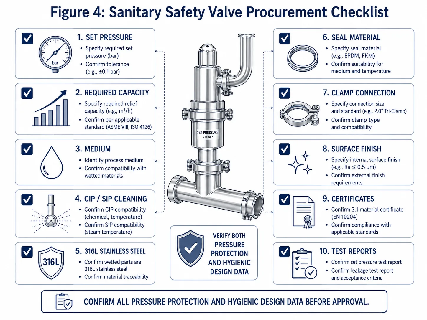
A complete RFQ combines pressure-protection data, hygienic design inputs, installation conditions and traceable documentation.
Sanitary Safety Valve Procurement Checklist
A request containing only clamp size, set pressure and 316L material is preliminary. The supplier cannot confirm capacity, valve construction, hygienic suitability or document scope from those fields alone.
Process Data to Provide
protected equipment tag and type;
MAWP, design pressure and design temperature;
normal and maximum operating pressure;
set pressure and code arrangement;
allowable overpressure or accumulation basis;
governing relief scenario and required relieving capacity;
medium composition and relieving phase;
operating and relieving temperature;
inlet piping and expected pressure loss;
superimposed and built-up back pressure;
outlet destination, drainage and simultaneous-relief condition;
history of chatter, leakage or previous repair for replacements.
Hygienic Design Data to Confirm
product-contact boundary and medium;
connection standard, size, ferrule and gasket geometry;
metallic product-contact material and heat traceability;
required surface finish and measurement basis;
electropolishing or passivation scope;
CIP chemicals, concentration, time, temperature and frequency;
SIP or clean-steam temperature, pressure, time and frequency;
seal compound, food-contact or pharmaceutical evidence;
drainability, installed orientation and dead-space limits;
pneumatic lift or cleaning function;
applicable ASME BPE, 3-A, EHEDG or owner requirements.
Documents to Request from the Supplier
approved valve datasheet and general arrangement drawing;
effective orifice and certified or documented capacity basis;
nameplate and applicable code-mark information;
metallic material certificates linked to the supplied valve;
elastomer identification, batch and regulatory declarations;
surface-finish inspection report;
passivation or electropolishing record when specified;
pressure-boundary test report;
set-pressure calibration certificate;
seat-tightness test report when specified;
hygienic certificate or declaration with exact product scope;
installation, drainage, cleaning and maintenance instructions;
repair, parts, recalibration and resealing records for repaired valves.
Questions to Ask Before Approval
Does the quoted valve protect the governing relief case with supported capacity?
Does the set pressure comply with the protected equipment and code arrangement?
Are the valve type and opening behavior correct for the medium and phase?
Are inlet loss and outlet back pressure within the supported limits?
Can the complete product-contact path be cleaned and drained in the installed position?
Does the exact seal compound tolerate production, CIP and SIP exposure?
Do hygienic and pressure certificates cover the exact model, size, materials and manufacturing entity?
Are calibration, seat testing, serial traceability and installation instructions included?
Is maintenance access sufficient for controlled disassembly, inspection and reassembly?
Inspection, Recalibration and Hygienic Return to Service
Opening the valve, changing a seat or elastomer, machining a nozzle, replacing a spring, disturbing an adjustment or repairing a bellows can affect both pressure performance and hygienic status. The valve should not be released only because it has been cleaned and reassembled.
Return-to-Service Check
What to Confirm
Why It Matters
As-found condition
Seal status, leakage, deposits, corrosion, set pressure where appropriate and previous lift history
Provides evidence for failure analysis and inspection interval review
Identifies seat damage, retained product, galling, corrosion and cleaning failure
Parts and material traceability
Exact replacement part, elastomer compound, batch, material certificate and approved interchangeability
Prevents undocumented substitutions that change pressure or hygienic performance
Cleaning and surface restoration
Approved cleaning method, residue removal, surface condition and passivation or electropolishing record when required
Restores the defined hygienic boundary without damaging critical dimensions
Pressure-function testing
Set pressure, pressure-boundary test and seat tightness under the specified procedure
Confirms the adjusted valve performs as required after intervention
Hygienic release
Cleanliness inspection, correct gasket installation, drainability, closure of open process paths and validation documentation where required
Confirms maintenance has not created a contamination or retention risk
Final identification
Serial number, test record, tag, lock, seal, maintenance date and responsible organization
Maintains traceability and prevents unapproved adjustment after release
Where the owner, jurisdiction or NBIC repair route requires it, pressure-relief-valve repair should be performed by an organization holding the applicable National Board VR authorization. VR authorization addresses the repair quality system and pressure-relief function; the owner must still define the sanitary cleaning, material and validation controls needed before the valve returns to product service.
A sanitary safety valve is an automatic reclosing pressure-relief device intended for hygienic or aseptic systems. It must protect the equipment from overpressure while providing product-contact geometry, materials, seals, connections and documentation suitable for the actual cleaning and sterilization conditions.
How is a sanitary safety valve different from a standard safety valve?
Both devices must satisfy the pressure-protection duty. A sanitary safety valve also requires hygienic product-contact design, cleanability, drainability, suitable surface condition, compatible elastomers and traceable documentation. A polished body or clamp connection alone does not establish hygienic suitability.
Can a standard industrial safety valve be used in a sanitary process line?
Only after a documented engineering and hygienic review. A standard valve may provide pressure relief but still create uncleanable cavities, retained product, unsuitable gasket interfaces, poor drainage or missing material and surface-finish evidence.
Can sanitary safety valves be used for clean steam?
Yes, when the selected valve has suitable steam capacity, materials, seat construction, temperature capability, drainage, discharge routing and documentation. Clean-steam service does not remove the need to verify set pressure, certified capacity, back pressure and post-lift seat condition.
What material is commonly used for sanitary safety valves?
316L stainless steel is commonly specified for product-contact parts, but the material grade alone does not establish hygienic suitability. Heat traceability, surface finish, weld and ferrule quality, internal geometry, drainability, passivation or electropolishing requirements, elastomers and cleaning conditions must also be reviewed.
What seal material should be used in a sanitary safety valve?
The seal must be selected by its actual formulation and documented conditions of use, not by polymer name alone. Product chemistry, CIP agents, SIP temperature, steam exposure, pressure cycling, compression set, extractables requirements and replacement interval all affect suitability.
Is clamp size enough to select a sanitary safety valve?
No. Clamp size establishes only the connection interface. Required relieving capacity must be compared with the selected valve’s certified or manufacturer-documented capacity and effective flow area under the approved fluid, pressure, temperature and back-pressure conditions.
What data should I provide when requesting a sanitary safety valve quotation?
Provide the protected equipment, MAWP or allowable limit, set pressure, overpressure or accumulation basis, governing relief scenario, required capacity, medium and phase, relieving temperature, operating margin, inlet and outlet conditions, back pressure, connection, materials, surface-finish requirement, CIP and SIP conditions, seal requirements and document package.
How do CIP and SIP conditions affect sanitary safety valve selection?
CIP and SIP can expose seals and product-contact parts to temperatures, chemicals, pressure cycles and contact times that are more severe than normal production. These conditions can change seal hardness, compression set, swelling, surface condition, leakage and maintenance intervals.
How does back pressure affect a sanitary safety valve?
Back pressure can affect opening stability, lift, effective capacity, blowdown and reseating. Closed recovery systems, condensate-filled outlets, sterilization headers and common discharge lines should be evaluated rather than treated as atmospheric discharge.
Why can a sanitary safety valve leak after sterilization?
Possible causes include incompatible or aged elastomers, thermal distortion, condensate retention, debris on the seat, operation close to set pressure, chatter, guide friction, chemical attack or incorrect reassembly. The leak path and root cause should be confirmed before the valve is returned to service.
What standards may apply to a sanitary safety valve?
The applicable framework may include ASME BPE, relevant 3-A Sanitary Standards or Accepted Practices, EHEDG hygienic-valve guidance, ASME BPVC Section XIII and the protected-equipment code, ISO 4126 product requirements, and project-specific food-contact or pharmaceutical requirements. Each document has a different scope.
Does a hygienic certificate prove relieving capacity?
No. A hygienic certificate or declaration may support cleanability, materials or hygienic design for a defined product scope. Relieving capacity, set pressure, pressure testing, code marking and installed-system suitability require separate evidence.
How often should a sanitary safety valve be inspected or recalibrated?
There is no universal interval for every sanitary valve. The interval should be based on the applicable code and owner program, service severity, CIP and SIP frequency, operating margin, corrosion or fouling risk, lift history, previous as-found results and manufacturer instructions.
What documents should a sanitary safety valve supplier provide?
The required package may include the approved datasheet and drawing, certified or documented capacity, nameplate data, material certificates, elastomer and food-contact declarations, surface-finish records, passivation or electropolishing records when specified, pressure-test report, set-pressure certificate, seat-tightness report, installation and cleaning instructions and repair records where applicable.
What must be reverified after a sanitary safety valve is repaired or its seals are replaced?
Reverify the approved parts and elastomer compound, product-contact cleanliness, surface condition, correct assembly, set pressure, seat tightness, tag and seal status, and any project-required hygienic release or validation records. A seal change can affect both leakage performance and CIP/SIP suitability.
Does ASME BPE or 3-A approval prove pressure-relief performance?
No. ASME BPE, 3-A and EHEDG-related evidence can support hygienic design, materials, cleanability or certification scope. Set pressure, relieving capacity, pressure testing, code marking, back-pressure limits and installed stability require separate pressure-relief evidence.
To provide the best experiences, we use technologies like cookies to store and/or access device information. Consenting to these technologies will allow us to process data such as browsing behavior or unique IDs on this site. Not consenting or withdrawing consent, may adversely affect certain features and functions.
Functional
Always active
The technical storage or access is strictly necessary for the legitimate purpose of enabling the use of a specific service explicitly requested by the subscriber or user, or for the sole purpose of carrying out the transmission of a communication over an electronic communications network.
Preferences
The technical storage or access is necessary for the legitimate purpose of storing preferences that are not requested by the subscriber or user.
Statistics
The technical storage or access that is used exclusively for statistical purposes.The technical storage or access that is used exclusively for anonymous statistical purposes. Without a subpoena, voluntary compliance on the part of your Internet Service Provider, or additional records from a third party, information stored or retrieved for this purpose alone cannot usually be used to identify you.
Marketing
The technical storage or access is required to create user profiles to send advertising, or to track the user on a website or across several websites for similar marketing purposes.