Share your medium, set pressure, temperature, size, standard, or datasheet, and our team will review your requirement and respond with the appropriate next step.
Selecting a spring loaded safety valve starts with the governing overpressure scenario, not with connection size, pressure class, or an old valve nameplate. The engineer must first confirm what can overpressure the protected equipment, how much mass or volumetric flow must be relieved, the fluid phase at relieving conditions, the set pressure basis, allowable overpressure or …
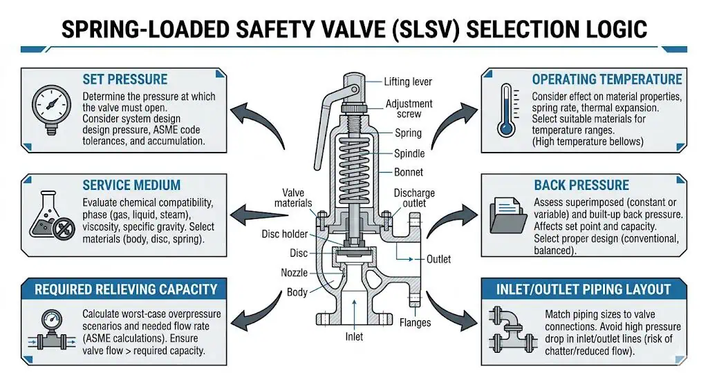
Selecting a spring loaded safety valve starts with the governing overpressure scenario, not with connection size, pressure class, or an old valve nameplate. The engineer must first confirm what can overpressure the protected equipment, how much mass or volumetric flow must be relieved, the fluid phase at relieving conditions, the set pressure basis, allowable overpressure or accumulation, expected back pressure, operating temperature, material compatibility, and the installed inlet and outlet piping. A spring-loaded valve is mechanically simple, but its field performance depends on the complete relief system.
A conventional spring-loaded safety valve can be a reliable choice for many steam, gas, vapor, air, and liquid applications when the service is compatible with its design limits. Problems usually appear when users treat the valve as an isolated catalog item. A valve can open at the correct set pressure during bench testing and still chatter because of excessive inlet pressure loss, lose effective capacity because of outlet back pressure, leak because normal operating pressure remains too close to set pressure, or fail early because the nozzle, disc, guide, spring environment, gasket, or soft seat is incompatible with the medium.
Common user concerns should therefore be translated into engineering checks:
Material and environmental conditions that affect corrosion, spring condition, guide movement, seat leakage, and service life.
Whether a conventional spring-loaded design is suitable for the expected back pressure and operating margin.
Whether required relieving capacity is supported by certified or project-accepted capacity data rather than inferred from connection size.
Whether the installation allows stable opening, safe discharge, inspection, testing, repair, and resealing.
Spring loaded safety valves remain a proven form of overpressure protection, but only when selection, installation, documentation, and maintenance are treated as one engineering process. For the basic mechanism, see how a spring-loaded safety valve works.
A sound selection starts with the governing relief case, required capacity, service medium, pressure and temperature limits, back pressure, materials, and installed piping—not with valve size alone.
What Users Should Confirm Before Selecting a Spring Loaded Safety Valve
Pressure, Temperature, and Operating Margin
Confirm normal operating pressure, maximum credible operating excursions, protected-equipment MAWP or other allowable pressure limit, set pressure, relieving pressure, and relieving temperature before selecting the valve. These values control when the valve starts to open, how much pressure rise is permitted during relief, the spring range, pressure-temperature rating, required orifice area, and the suitability of body, trim, gaskets, bellows, and seat materials.
Operating margin is the separation between normal operating pressure and the valve’s opening region. It is not a universal fixed percentage. The acceptable margin depends on valve design, service cleanliness, pressure pulsation, seat type, temperature, required tightness, blowdown behavior, manufacturer data, and the governing project standard. A clean gas system with a stable pressure profile may tolerate a different margin from wet steam, reciprocating-compressor discharge, dirty hydrocarbon service, or a system with frequent pressure cycling.
Engineering note: A balanced bellows design may reduce the effect of outlet back pressure, but it does not automatically solve poor operating margin, inlet pressure loss, incorrect sizing, dirty service, or incompatible materials. Each problem must be evaluated separately.
Operating too close to set pressure can increase simmer, seat leakage, erosion, and unstable long-term service. The required margin depends on the valve and actual process conditions.
The following parameters should be confirmed as separate data fields rather than combined into a single “design pressure” entry:
Parameter
What It Controls
Selection Risk If Missing
Normal and maximum operating pressure
Operating margin, simmer risk, and seat-tightness requirement.
Premature leakage, cycling, or nuisance lift.
MAWP or protected-equipment pressure limit
Upper boundary used with the applicable code and set-pressure arrangement.
Incorrect set pressure or non-compliant protection basis.
Set pressure
The adjusted pressure at which the valve begins its specified opening response.
Protection starts too late or the valve opens during normal operation.
Relieving pressure and allowable accumulation
Available pressure for capacity and the maximum temporary system pressure during the event.
Incorrect sizing or unacceptable overpressure.
Relieving temperature
Fluid properties, material strength, spring behavior, gasket and seat suitability.
Wrong capacity calculation or material damage.
Back pressure
Opening stability, effective capacity, blowdown, and reseating.
Chatter, reduced capacity, or post-relief leakage.
Composite engineering scenario: A gas receiver valve was repeatedly repaired for seat leakage. The shop test results were acceptable, but the receiver operated for long periods just below the set pressure and experienced compressor pulsation. The seat was not the root cause. The combination of insufficient operating margin and pressure cycling caused simmer and progressive seat damage. The corrective action was to review the operating envelope, pressure-control strategy, seat configuration, and set-pressure basis rather than repeatedly lap the same seat.
Fluid Type, Cleanliness, and Required Relieving Capacity
Confirm the fluid phase and properties at relieving conditions, not only the normal process description. Gas, vapor, steam, liquid, flashing liquid, and two-phase flow require different sizing assumptions and can produce different opening and discharge behavior. Density, molecular weight, compressibility, viscosity, specific heat ratio, saturation condition, and relieving temperature may all affect required orifice area.
Service cleanliness also changes the valve-selection boundary. Deposits, coke, wax, polymer, corrosion products, ice, scale, or sticky liquid can damage the seat, restrict the inlet, increase guide friction, or prevent full lift. Outdoor protection should prevent weather and contamination without blocking bonnet vents, drains, or required discharge openings.
Define whether the relieving case is gas, vapor, steam, liquid, flashing, or two-phase.
Identify solids, deposits, polymerization, freezing, hydrate, or fouling risks.
Confirm whether a metal seat or soft seat is suitable for temperature, cleanliness, and leakage requirements.
Do not add covers, insulation, or weather protection that interferes with lifting levers, bonnet vents, pilot tubing, or drainage.
Specify cleaning and preservation requirements where oxygen, cryogenic, corrosive, or high-purity service demands them.
Required relieving capacity is the flow demand established by the governing overpressure scenario. Certified or project-accepted relieving capacity is the documented performance of the selected valve, orifice, set pressure, fluid, and configuration. The valve is acceptable only when the documented capacity meets or exceeds the required capacity under the approved sizing basis.
Review Step
Engineering Purpose
Common Error
Define the overpressure scenario
Establishes the required relief load.
Using normal flow instead of blocked outlet, fire, tube rupture, regulator failure, thermal expansion, or another governing case.
Determine relieving fluid properties
Supports the correct sizing method.
Using normal-condition density or ignoring flashing/two-phase behavior.
Calculate required relieving capacity
Defines the minimum protective flow.
Selecting by line size or old valve connection.
Select required orifice area
Converts the relief load into a minimum flow area.
Confusing inlet flange size with effective orifice.
Verify certified or accepted capacity
Confirms the selected valve can satisfy the duty.
Accepting a catalog model without capacity documentation.
Apply back-pressure and combination-device corrections
Accounts for discharge-system and rupture-disk effects where applicable.
Using free-discharge capacity for a closed-header installation.
How to Select Set Pressure, Overpressure, and Blowdown
Calculating Set Pressure Against MAWP and Operating Conditions
Set pressure must be established from the protected equipment’s allowable pressure limit and the applicable code arrangement—not from a universal “110% of MAWP” rule. For many pressure-vessel applications, the valve set pressure is not permitted to exceed the MAWP except where the governing code specifically provides a multiple-device or supplemental arrangement. Boiler, pressure-vessel, piping, and local regulatory requirements should not be mixed.
A practical review sequence is:
Identify the protected equipment and governing code or owner specification.
Confirm MAWP, design pressure, maximum operating pressure, and any permitted multiple-device arrangement.
Establish the set pressure within the applicable code limits.
Check that normal operating pressure and expected process fluctuations provide a suitable margin below the valve’s opening region.
Confirm allowable overpressure or accumulation for the governing scenario.
Verify that the selected spring range, temperature correction, valve type, and test method support the chosen setting.
Important: Do not use a fixed “15–20% above maximum operating pressure” rule as a substitute for code review and manufacturer data. Operating margin is service- and design-dependent.
Overpressure, Accumulation, and Blowdown in Spring Loaded Designs
Overpressure, accumulation, and blowdown describe different parts of the relieving event and should not be used as synonyms. Their exact allowable values depend on the governing code, protected equipment, number and type of devices, and overpressure scenario.
Set pressure: The pressure at which the valve is adjusted to begin its specified opening response.
Overpressure: The pressure increase above the valve set pressure during a relieving event.
Accumulation: The pressure increase above the protected equipment’s MAWP or other allowable pressure boundary during the event.
Blowdown: The difference between set pressure and reseating pressure, usually expressed as pressure or percentage of set pressure.
The spring provides the closing force, but full-lift and reseating behavior also depend on nozzle and disc geometry, huddling-chamber action, adjusting rings where fitted, fluid compressibility, inlet loss, outlet back pressure, and the selected orifice relative to the actual load. A valve can have the correct set pressure but poor blowdown or unstable lift because the installed system does not match the test conditions.
Term
Engineering Meaning
Why It Matters
Set pressure
Adjusted opening reference for the valve.
Determines when protective action begins.
Overpressure
Pressure above set pressure while relieving.
Provides the pressure differential used to achieve rated flow.
Accumulation
Pressure above the protected equipment limit during the event.
Determines whether the equipment remains within the permitted temporary pressure boundary.
Blowdown
Difference between opening and reseating pressure.
Affects process recovery, cycling, product loss, and seat condition.
Composite engineering scenario: A steam safety valve opened at the specified set pressure but remained open longer than the operating team expected and leaked after reseating. Inspection found seat damage, while review showed that condensate drainage and discharge piping support were poor and the blowdown setting had been altered during an earlier repair. The prevention was to restore the approved adjustment, improve outlet drainage and support, complete a seat-tightness test, and reseal the valve after recalibration.
A spring-loaded safety valve does not require an external controller, but it still depends on correct mechanical adjustment, stable inlet conditions, acceptable outlet pressure, suitable materials, and controlled post-repair testing.
How to Size Capacity for a Spring Loaded Safety Valve
Required Relieving Capacity and Orifice Selection
Start with the required relieving capacity, calculate the minimum required area, then select a valve with documented capacity that satisfies the case. The required capacity comes from the overpressure scenario. The required area comes from the applicable sizing method. The final selected orifice and valve capacity come from certified or manufacturer-supported data.
An undersized valve may open yet allow pressure to continue rising beyond the permitted accumulation. An excessively oversized valve may cycle, chatter, or suffer rapid seat damage when the actual relief load cannot sustain stable lift. Oversizing is not automatically conservative.
It is a product standard and does not replace application-specific system analysis.
Manufacturer sizing software
Applies product data, coefficients, correction factors, and available models.
Results are only as reliable as the input data and selected calculation basis.
The original article’s unsupported numerical sizing example has been removed. A capacity example is only trustworthy when the fluid, phase, molecular weight or density, relieving pressure, temperature, back pressure, coefficient basis, and selected standard are all stated. Without those inputs, a quoted area cannot be independently checked.
Manufacturer Sizing Tools, Charts, and What They Do Not Replace
Manufacturer sizing tools are useful for product selection, but they do not define the relief scenario or approve the complete installation. A tool can calculate required area and propose a model only after the engineer supplies correct process and code data.
Independently verify units, relieving conditions, fluid phase, and property data.
Confirm whether the tool uses certified coefficients, rated coefficients, or preliminary estimates.
Check inlet pressure loss, superimposed and built-up back pressure, rupture-disk combinations, and outlet-system effects separately.
Confirm the valve model’s pressure-temperature rating, spring range, material options, and certified capacity.
Retain the input sheet, calculation basis, software version, and final selection report in the project file.
Engineering rule: Sizing software does not correct an undefined relief case, inaccurate fluid data, wrong code basis, or unsuitable piping layout.
When a Spring Loaded Safety Valve Is the Right Choice and When It Is Not
Valve type should follow back pressure, service cleanliness, operating margin, tightness requirement, temperature, and maintenance capability—not purchasing habit.
Suitable Applications for Spring Loaded Safety Valves
A conventional spring-loaded safety valve is often appropriate where the service is compatible, the relief load is defined, inlet loss is controlled, and outlet back pressure remains within the selected design’s allowable range. It provides automatic mechanical operation without an external power source or control system.
Steam and boiler duties where the valve is designed, certified, and installed for the applicable boiler code route.
Clean gas, air, and vapor systems with stable operating pressure and acceptable back pressure.
Pressure-vessel and process applications where a direct spring-loaded device satisfies capacity, material, tightness, and installation requirements.
Liquid relief applications where the selected valve is designed and certified for liquid service.
Utility and packaged-equipment service where simple maintenance and direct mechanical operation are preferred.
The term “spring loaded safety valve” should not be used to blur the difference between safety valves, relief valves, safety relief valves, and PSV terminology. Steam or gas pop-action duty is not the same as proportional liquid-relief duty. The datasheet should define the actual service and certification basis. See PRV vs PSV vs safety valve vs relief valve.
When to Consider Balanced Bellows or Pilot-Operated Alternatives
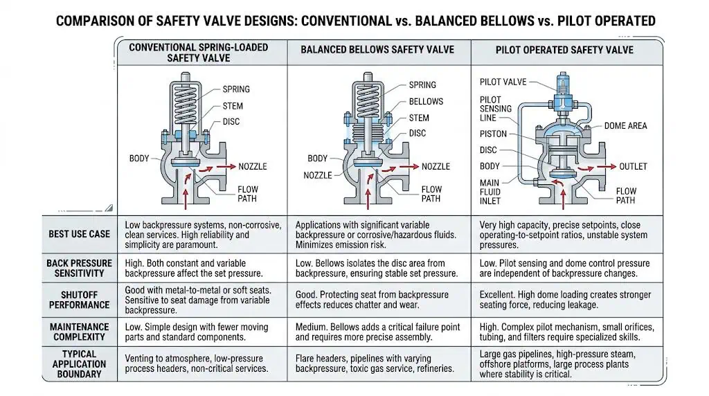
Review a balanced bellows or pilot-operated design when the limitations of a conventional spring-loaded valve are relevant to the actual service. High inlet pressure loss is not, by itself, a reason to select a pilot-operated valve; the inlet system still requires engineering correction or analysis. Likewise, steam service does not automatically require a balanced or pilot-operated design.
Condition
Conventional Spring-Loaded
Balanced Bellows
Pilot-Operated
Low and predictable back pressure
Often suitable within manufacturer limits.
May be unnecessary.
May be unnecessary unless other requirements apply.
Variable or significant outlet back pressure
May become unsuitable depending on design.
Often reviewed to reduce back-pressure influence.
May be reviewed if service cleanliness and project acceptance are suitable.
Corrosive discharge media
Spring chamber exposure must be reviewed.
Bellows may isolate components, but bellows material and bonnet venting become critical.
Pilot materials and sensing passages require review.
Operating pressure close to set pressure
Seat leakage or simmer may be a concern.
Back-pressure balancing does not automatically improve seat tightness.
May provide tighter shutoff in suitable clean service.
Dirty, waxy, polymerizing, or freezing service
May be more tolerant, depending on trim and inlet condition.
Bellows and guides still require contamination review.
Pilot passages and sensing lines may plug or freeze.
Maintenance capability
Generally simpler.
Adds bellows inspection and vent requirements.
Adds pilot, tubing, filter, and sensing-system maintenance.
Composite engineering scenario: A pilot-operated valve was installed on a dirty hydrocarbon service because the operating pressure was close to set pressure. The main valve remained tight initially, but condensate and solids entered the sensing system and caused unstable pilot behavior. The corrective action included cleaning and redesigning the sensing arrangement, but the long-term review also considered whether a spring-loaded or balanced-bellows design was more tolerant of the actual medium.
Material and Installation Considerations That Affect Real Performance
Material Compatibility for Body, Nozzle, Disc, Spring, and Soft Parts
Material selection must cover every pressure-retaining, wetted, guiding, sealing, and force-producing component—not only the valve body. A carbon-steel body may be acceptable while stainless trim fails from chloride stress corrosion, a spring corrodes through bonnet exposure, a soft seat swells in the process fluid, or a guide sticks because deposits attack its clearance.
Component
Engineering Function
Material Review
Body and bonnet
Contain pressure and support the internal assembly.
Pressure-temperature rating, external atmosphere, corrosion allowance, brittle-fracture risk, and code material acceptance.
Nozzle and seat
Form the primary flow entrance and sealing surface.
Erosion, corrosion, galling, hardness pairing, deposit formation, and seat-tightness requirement.
Disc and disc holder
Open, modulate or pop, and reseat against the nozzle.
Impact, erosion, corrosion, thermal distortion, and compatibility with the seat.
Guide and spindle
Maintain alignment of moving components.
Friction, galling, fouling, corrosion products, and clearance at temperature.
Spring
Provides the calibrated closing force.
Temperature exposure, corrosion, relaxation, fatigue, coating, and environment inside the bonnet.
Bellows, if fitted
Reduces outlet-pressure influence and may isolate the spring chamber.
Pressure limit, fatigue, corrosion, temperature, material compatibility, and vent arrangement.
Soft seat, O-rings, and gaskets
Improve sealing or contain internal leakage paths.
Chemical compatibility, temperature, decompression damage, ageing, swelling, and fire-service limitations.
Material designations such as WCC, LCC, CF8M, duplex, Monel, Inconel, or Hastelloy do not prove suitability by name alone. The actual ASTM/ASME grade, pressure-temperature rating, heat treatment, trim specification, fluid composition, temperature, chloride content, H2S exposure, and owner requirements must be checked. Sour service may require NACE MR0175 / ISO 15156 review where specified.
Composite engineering scenario: A valve with a stainless-steel body was approved for chloride-bearing condensate, but the nozzle and guide materials were not reviewed separately. After one service cycle, the valve developed seat leakage and guide drag. Inspection found localized corrosion on the trim while the body remained visually sound. The corrective action was to specify the complete wetted trim and guide materials rather than using body material as a shortcut.
Connection Types, Orientation, and Inlet / Outlet Piping Effects
Connection type must satisfy pressure, temperature, maintenance, leakage, and project-standard requirements, but it does not determine relieving capacity by itself. Flanged connections support standardized project interfaces and easier removal. Threaded valves may suit smaller, lower-inventory or utility applications when permitted. Welded connections reduce external leakage paths but make removal and repair more difficult.
Most direct spring-loaded safety valves should be installed upright with the spindle vertical unless the manufacturer specifically approves another orientation. Vertical installation supports predictable spring, guide, disc, drainage, and reseating behavior.
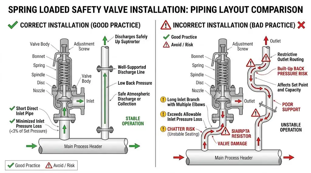
Inlet and outlet piping must be reviewed as part of the valve selection:
Keep the inlet connection short, direct, and free of unnecessary restrictions.
Evaluate inlet pressure loss at relieving flow, not only at normal operating conditions.
Do not apply the familiar “3% rule” as a universal substitute for the current API 520 Part II requirements and engineering analysis.
Confirm that outlet resistance and the receiving header do not create unacceptable superimposed or built-up back pressure.
Support discharge piping independently and evaluate reaction, thermal, vibration, and acoustic loads.
Provide drains and bonnet vents as required, without creating blocked or hazardous discharge paths.
Field performance depends on relieving-flow inlet loss, outlet resistance, back pressure, drainage, support, and whether the installed layout matches the approved sizing basis.
Piping Factor
Potential Effect
Required Review
Restrictive inlet branch
Pressure collapse at the valve inlet, chatter, reduced lift, and seat damage.
Relieving-flow pressure-loss and dynamic-stability review.
Long or undersized outlet line
Built-up back pressure, noise, vibration, and reduced effective performance.
Outlet hydraulic calculation and valve back-pressure limit.
Common discharge header
Variable superimposed pressure and simultaneous-relief interaction.
Header analysis using credible relief combinations.
Unsupported discharge elbow
Excessive mechanical load on the valve and equipment nozzle.
Piping support, reaction-force, and thermal-expansion analysis.
Horizontal installation without approval
Guide friction, uneven wear, poor drainage, and leakage.
Manufacturer approval or redesign for upright mounting.
For a detailed installation review, see the safety valve installation guide. API 520 Part II’s current edition specifically includes an engineering-analysis route for installations that require more than a simple screening check.
Compliance, Documentation, and Buyer Review Points
Codes, Certifications, and Required Technical Documents
The applicable standard depends on the protected equipment, service, market, and project specification. Listing many standards does not prove compliance. Each document has a different scope and should be used for the question it actually addresses.
Design, manufacture, and conformity assessment of stationary pressure equipment and safety accessories within its scope.
The former PED 97/23/EC reference has been removed because the applicable recast directive is PED 2014/68/EU. “EN4126” has also been corrected to the relevant ISO 4126 family or applicable harmonized EN ISO adoption used by the project.
A procurement package should define the required documents rather than rely on a generic statement such as “ASME compliant.” Typical records include:
Identity, set pressure, model, size, capacity marking, and certification route.
Certified or accepted capacity data
That the selected valve and configuration satisfy the required relief load.
Material certificates
Traceability of body, bonnet, nozzle, disc, spring, bellows, and other specified components.
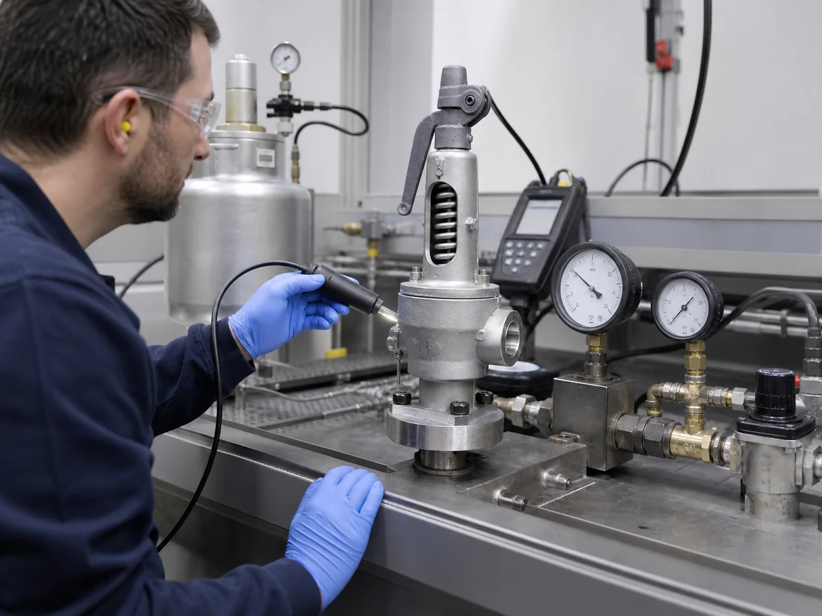
Set-pressure and seat-tightness test records
Adjustment and leakage performance under the specified test method.
Pressure test and NDE records
Product integrity where required by the code or purchase specification.
Manufacturer installation and maintenance manual
Product-specific orientation, back-pressure, venting, handling, and maintenance requirements.
Repair and recalibration history
Who changed the valve, what was replaced, test results, seal status, and return-to-service basis.
Where the owner, jurisdiction, or applicable ASME/NBIC route requires recognized pressure-relief-valve repair authorization, verify the repair organization’s National Board VR authorization.
Additional Features and Buyer Checkpoints
Additional features should be specified only when the service and operating procedure justify them. A lifting lever, test gag, open or closed bonnet, balanced bellows, soft seat, heating jacket, or special coating can be useful, but each also creates operating, inspection, or maintenance requirements.
Confirm whether a lifting lever or other test device is required or permitted for the service.
Define metal-seat or soft-seat leakage expectations and the applicable seat-tightness test.
Check whether an open, closed, or gas-tight bonnet is required by fluid and discharge conditions.
Confirm whether a test gag is allowed and how its removal will be controlled before operation.
Verify bellows vent routing and inspection access if a balanced bellows design is selected.
Confirm spring material, coating, and bonnet environment for corrosive or high-temperature duty.
Specify low-temperature, sour-service, oxygen-cleaning, fire-safe, sanitary, or fugitive-emission requirements only when technically applicable.
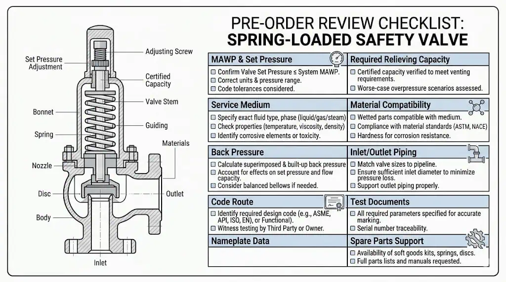
Pre-order review should confirm the relief scenario, code route, set pressure, required and certified capacity, back pressure, materials, installation, test records, and repair pathway together.
A controlled safety valve datasheet for RFQ reduces the risk of receiving quotations that match only size and set pressure while missing the actual protective duty.
A complete technical offer should explain what the valve is selected to protect, which relief case controls, what capacity is supported, what back pressure is allowed, what materials are supplied, and which documents will be delivered.
Common Spring Loaded Safety Valve Selection Mistakes
Choosing by Pressure Class or Size Instead of Capacity and Service Conditions
Mistake: Selecting a spring-loaded safety valve because its inlet flange, outlet flange, pressure class, and set pressure resemble the existing valve.
Pressure class confirms the pressure-temperature capability of the connection and body within the applicable material rating. Connection size confirms physical fit. Neither proves required relieving capacity, certified capacity, fluid suitability, blowdown performance, or back-pressure tolerance.
Composite engineering scenario: A plant purchased a same-size replacement after a debottlenecking project. The valve fit the nozzle and was set correctly, but the new process throughput increased the blocked-outlet relief load. The selected model had a smaller effective orifice and insufficient documented capacity. The correction required a new sizing review and a different valve rather than a simple dimensional replacement.
Prevention requires checking the current relief scenario, required capacity, selected orifice, certified capacity, fluid, temperature, back pressure, and installation. Physical interchangeability is not engineering equivalence.
Ignoring Back Pressure, Inlet Loss, and Operating Margin
Mistake: Assuming that a correct set pressure guarantees stable field operation.
Key Factor
Effect on Spring-Loaded Safety Valves
Correct Review
Inlet pressure loss
Can cause pressure collapse at the inlet, chatter, reduced lift, and seat damage.
Evaluate at relieving flow using the applicable installation standard and engineering analysis.
Superimposed back pressure
May change the force balance before opening.
Confirm whether it is constant or variable and compare with valve design limits.
Built-up back pressure
Can affect lift, effective capacity, blowdown, and reseating.
Calculate the outlet system at credible relief flow and header conditions.
Operating margin
Insufficient margin can cause simmer, leakage, and premature wear.
Use manufacturer data, service stability, seat type, and project requirements—not a universal percentage.
Oversized orifice
May create unstable lift when the actual flow cannot sustain the valve.
Select the smallest certified orifice that safely satisfies the required load, subject to the applicable basis.
When plant conditions change, the relief system should be revalidated. A new compressor, higher throughput, modified control valve, longer discharge line, silencer, flare-header tie-in, or changed operating pressure can invalidate the original selection even when the valve itself has not changed.
Overlooking Maintenance and Repair Reality
Mistake: Selecting a valve without considering inspection access, spare parts, test capability, repair authorization, and the consequences of repeated leakage or chatter.
Inspect seat and nozzle condition, guide freedom, spindle alignment, spring condition, corrosion, deposits, and bellows condition where fitted.
Review failure history rather than resetting the same valve repeatedly without root-cause analysis.
After repair, verify set pressure, blowdown or reseating behavior where applicable, seat tightness, replacement parts, sealing, and documentation.
Do not mix springs, trim, adjusting rings, or internal parts from different models without manufacturer-approved interchangeability.
Confirm that the repair organization and test facility satisfy the project’s quality and authorization requirements.
Shorten inspection intervals where corrosive, dirty, cyclic, high-temperature, sour, or high-consequence service history justifies it.
A valve that repeatedly leaks may be showing an operating-margin, piping, material, contamination, or back-pressure problem. Re-lapping the seat without correcting the system cause can return the valve to the same failure mode.
Start every spring loaded safety valve selection with the governing relief scenario, required relieving capacity, protected-equipment pressure limit, fluid phase, relieving temperature, and installed piping. Then confirm set pressure, allowable overpressure or accumulation, blowdown, certified capacity, back pressure, material compatibility, orientation, seat tightness, documentation, and maintenance pathway.
Reliable protection depends on the complete pressure-relief system. The valve body, inlet line, outlet system, process conditions, test records, and repair controls must support the same engineering basis.
A final engineering and procurement checklist should include:
Protected equipment and governing overpressure scenario.
Fluid composition, phase, cleanliness, and relieving temperature.
Operating pressure, MAWP or allowable limit, set pressure, overpressure, accumulation, and blowdown.
Required relieving capacity, selected orifice, and certified or accepted capacity.
A checklist-based review before ordering, installing, or replacing a valve is more reliable than trying to correct selection mistakes after commissioning.
FAQ
What is the main advantage of a spring loaded safety valve?
Its main advantage is direct, self-actuated mechanical pressure relief without an external control or power source. A properly selected spring-loaded safety valve can provide reliable overpressure protection in many steam, gas, vapor, air, and liquid services. Its simplicity does not remove the need for correct sizing, stable inlet piping, acceptable back pressure, compatible materials, and controlled maintenance.
How does back pressure affect spring loaded safety valves?
Back pressure can affect opening force balance, lift, effective relieving capacity, blowdown, and reseating. Superimposed back pressure exists before opening, while built-up back pressure develops during flow through the outlet system. The allowable effect depends on whether the valve is conventional, balanced bellows, or another design and must be checked against manufacturer and project data.
When should users choose a balanced bellows or pilot-operated valve?
Review a balanced bellows valve when variable or significant outlet back pressure makes a conventional spring-loaded valve unsuitable. Review a pilot-operated valve when tight shutoff, high operating-pressure ratio, capacity, or specific back-pressure behavior justifies it and the service is clean enough for reliable pilot operation. Neither alternative corrects an undefined relief case or poor inlet piping.
What maintenance does a spring loaded safety valve require?
Maintenance should include inspection, cleaning, dimensional and condition checks, set-pressure testing, seat-tightness testing, approved replacement of damaged components, documentation, and resealing. The interval depends on code requirements, service severity, corrosion, contamination, cycling history, failure consequences, and previous test results.
How should set pressure be selected against MAWP?
Set pressure must be established within the limits of the governing code for the protected equipment. Do not apply a universal rule allowing set pressure to exceed MAWP. Boiler, pressure-vessel, multiple-device, supplemental, and local regulatory arrangements can differ. The responsible engineer should confirm the exact code provision and owner specification.
How much operating margin is required below set pressure?
There is no universal percentage suitable for every spring-loaded safety valve. The required margin depends on valve design, seat type, process stability, pressure pulsation, temperature, service cleanliness, blowdown, required tightness, manufacturer guidance, and the applicable project standard.
Why is certified relieving capacity more important than connection size?
Connection size confirms physical fit, while certified relieving capacity confirms whether the valve can pass the required relief load. Two valves with the same inlet and outlet sizes can have different effective orifices, lift, coefficients, certified capacities, and permitted service conditions.
What materials are suitable for corrosive service?
Material selection depends on the exact medium, concentration, contaminants, temperature, pressure, phase, velocity, and applicable material standard. The review must cover body, nozzle, disc, guide, spindle, spring environment, bellows, gaskets, and soft seats. Stainless steel alone is not proof of compatibility; duplex, nickel alloys, Monel, Hastelloy, or other materials may be required for specific services.
Why does a spring loaded safety valve leak after installation?
Post-installation leakage may result from dirt, seat damage, pipe strain, improper handling, operation too close to set pressure, vibration, thermal distortion, corrosion, outlet back pressure, or incorrect repair adjustment. Troubleshooting should compare shop test records with installed conditions and examine the complete inlet, outlet, process, material, and maintenance history.
Is the 3% inlet pressure-loss rule always applicable?
No. The familiar 3% criterion is an important screening concept in conventional PRV installation practice, but it should not be applied blindly to every valve, fluid, or dynamic system. The current API 520 Part II framework includes an engineering-analysis route. The applicable edition, valve type, fluid behavior, acoustics, piping geometry, and manufacturer limits must be considered.
To provide the best experiences, we use technologies like cookies to store and/or access device information. Consenting to these technologies will allow us to process data such as browsing behavior or unique IDs on this site. Not consenting or withdrawing consent, may adversely affect certain features and functions.
Functional
Always active
The technical storage or access is strictly necessary for the legitimate purpose of enabling the use of a specific service explicitly requested by the subscriber or user, or for the sole purpose of carrying out the transmission of a communication over an electronic communications network.
Preferences
The technical storage or access is necessary for the legitimate purpose of storing preferences that are not requested by the subscriber or user.
Statistics
The technical storage or access that is used exclusively for statistical purposes.The technical storage or access that is used exclusively for anonymous statistical purposes. Without a subpoena, voluntary compliance on the part of your Internet Service Provider, or additional records from a third party, information stored or retrieved for this purpose alone cannot usually be used to identify you.
Marketing
The technical storage or access is required to create user profiles to send advertising, or to track the user on a website or across several websites for similar marketing purposes.