Threaded Connection • Compact Safety Relief Valves
Threaded Safety Valves Manufacturer for Air, Water, Steam and Compact Systems
Threaded safety valves are pressure relief valves with screwed inlet or outlet connections for compact pressure equipment, air receivers, compressors, water systems, utility steam lines and skid-mounted systems. They are often specified as threaded pressure safety valves, threaded safety relief valves, NPT safety valves, BSP safety valves or threaded PRVs.
ZOBAI supplies threaded safety valves with engineering support for set pressure, relieving capacity, thread size, thread standard, medium, temperature, material, discharge direction and project documentation. For requests such as 2 threaded safety valve 500 psi, our team can help confirm whether 500 psi refers to set pressure, system rating or another pressure condition before quotation.
Connection: NPT / BSP / G / Rc / Custom Thread
Service: Air / Water / Steam / Gas / Liquid
Key Checks: Set Pressure / Capacity / Thread Standard / Material
Options: Spring Loaded / Lever / Pilot Operated / Sealed Cap
Sizes: Compact Sizes / 1 Inch / 2 Inch Options
Docs: Datasheet / Test Report / Calibration Record / Material Certificate
Threaded safety valve selection should be confirmed against the actual medium, set pressure, operating pressure, required relieving capacity, temperature, thread size, thread standard, material, discharge system and applicable code requirements.
Safety Valve Categories
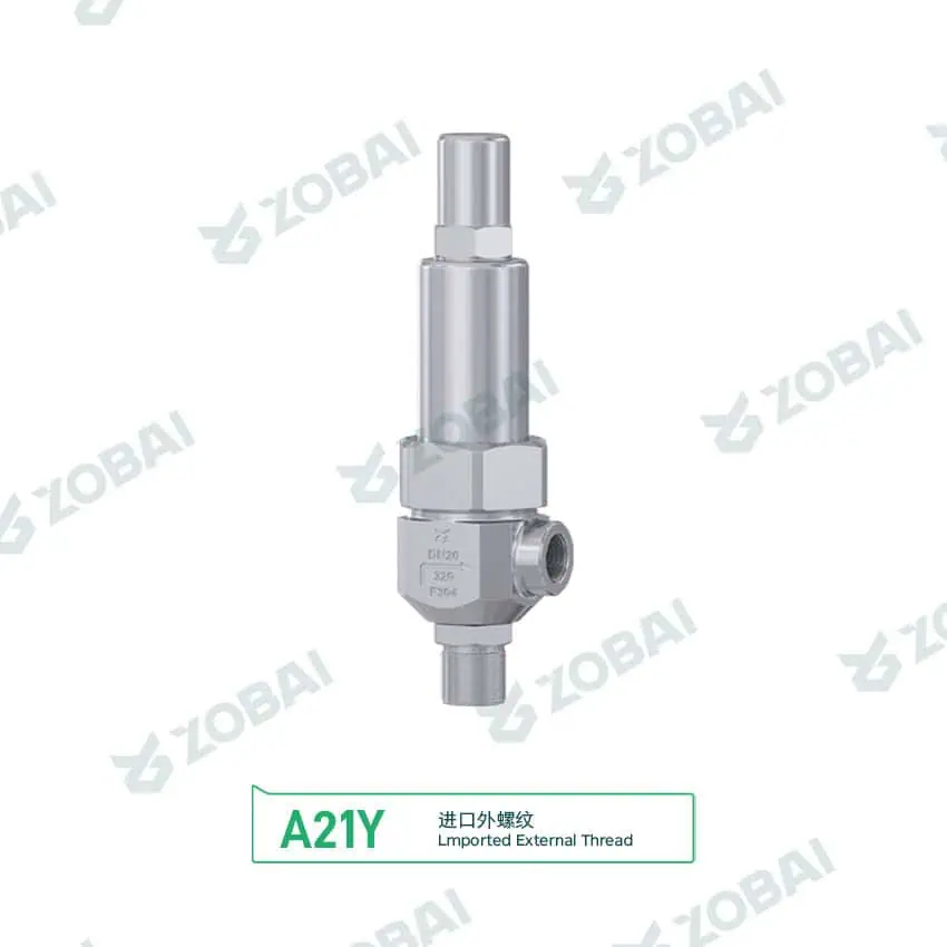
A21Y DN20 Male Thread Safety Valve
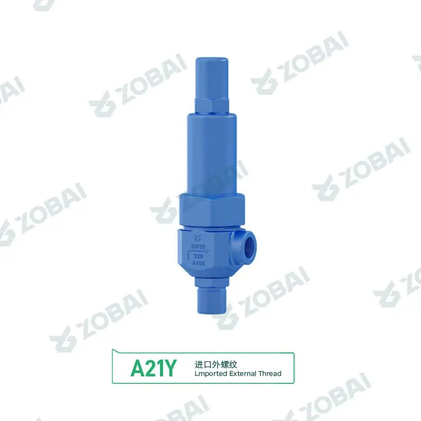
A21Y DN20 A105 Male Thread Safety Valve
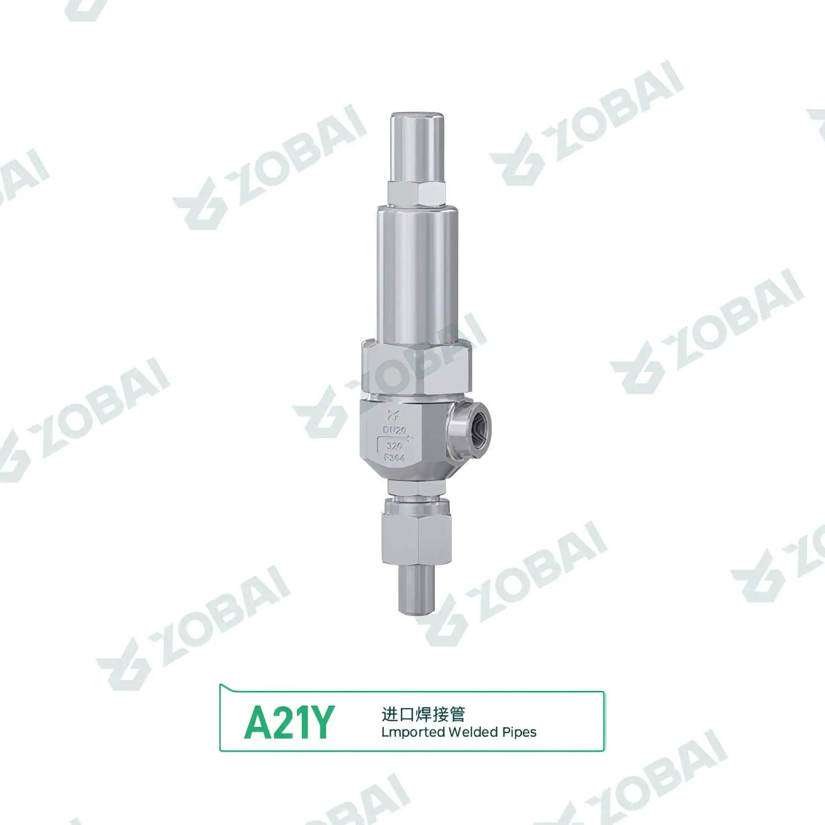
A21Y DN20 Welded Pipe Safety Valve
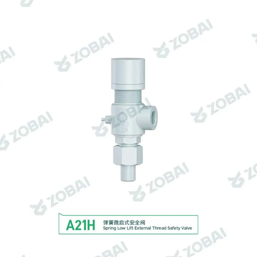
A21H DN15 Pipe Union Safety Valve
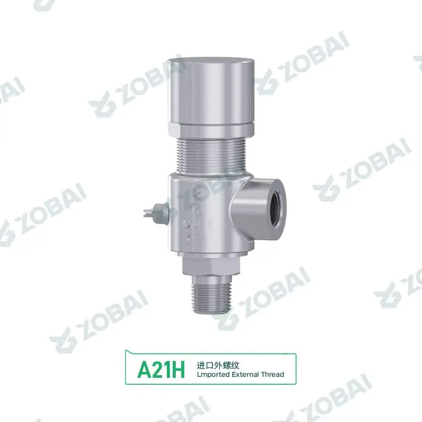
A21H DN15 Stainless Male Thread Safety Valve
A21H DN15 Male Thread Safety Valve
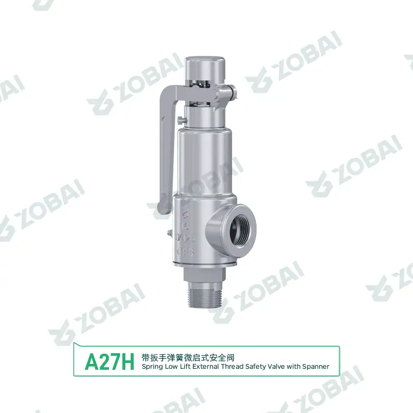
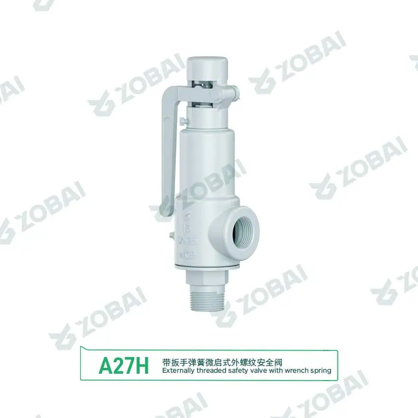
A27H DN25 Stainless Threaded Safety Valve
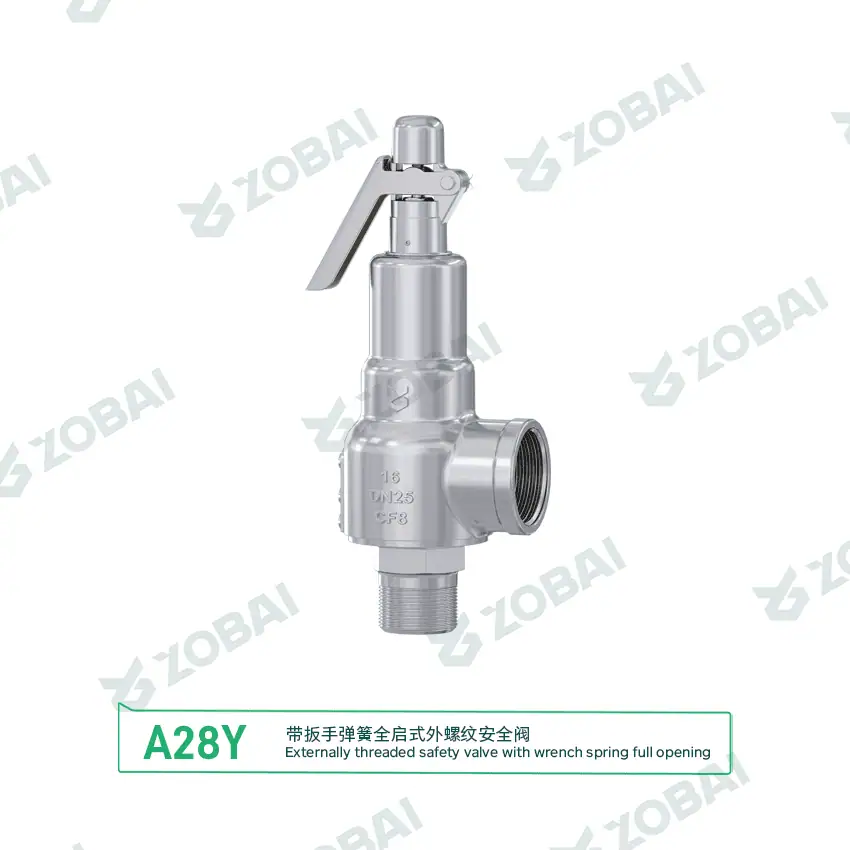
A28Y DN25 Full Lift Threaded Safety Valve
ZBXY 0.75 Inch Female Thread Inlet Relief Valve
ZBXY 0.75 Inch Male Thread Inlet Relief Valve
Threaded Safety Valves for Compact Pressure Protection Systems
Threaded safety valves are pressure relief valves with screwed inlet or outlet connections, commonly used on compact pressure vessels, compressors, air receivers, water systems, small process skids, utility steam lines and equipment where threaded piping is specified. They are often requested as threaded pressure safety valves, threaded safety relief valves, NPT safety valves, BSP safety valves or 2-inch threaded safety valves.
Why threaded connection details matter
A threaded safety valve is not selected only by thread size. The connection form, thread standard, pressure rating, set pressure, required relieving capacity, medium, temperature, material and installation direction all affect whether the valve can protect the equipment correctly.
For example, a buyer may request a 2-inch threaded safety valve for 500 psi service, but that phrase does not confirm the medium, capacity, orifice, temperature, thread standard or whether the valve is spring loaded or pilot operated. Before quotation, the thread type and pressure relief data must be converted into a complete engineering requirement.
Selection boundary
Threaded safety valves are usually suitable for smaller line sizes, compact equipment, lower-to-medium flow requirements and systems where screwed connections are already part of the piping design. For large capacity, high vibration, severe thermal cycling, frequent disassembly or heavy piping loads, flanged or welded connections may be more suitable.
A 1-inch or 2-inch threaded valve still needs capacity verification. Set pressure, orifice area, medium properties and certified relieving capacity matter more than the nominal thread size.
How a Threaded Safety Valve Works
A threaded safety valve works like other pressure relief valves: the disc remains closed during normal operation and opens automatically when system pressure reaches the set pressure. The threaded connection provides the mechanical interface to the protected system. Correct installation is critical because thread engagement, sealing method, pipe stress and discharge direction can affect leakage, stability and maintenance safety.
Normal Operation
The valve remains closed while pressure stays below set pressure. Thread seal quality and piping alignment help prevent external leakage.
Pressure Reaches Set Point
When pressure reaches the set pressure, the disc starts to lift and the valve begins relieving excess pressure.
Relieving Flow
The valve must discharge the required flow through the selected orifice and outlet path, not only through the visible connection size.
Reseating
After pressure falls, the valve reseats. Vibration, outlet restriction, thread stress or dirt can affect reseating and leakage.
Key Thread and Connection Details to Confirm
Threaded safety valve failures often come from wrong connection assumptions rather than the pressure relief mechanism itself. Thread form, sealing method, engagement length, installation torque and outlet orientation should be confirmed before ordering.
NPT, BSP and Other Thread Standards
Threaded safety valves may use NPT, BSP, Rc, G or project-specific threaded connections. These are not interchangeable. A valve ordered with the wrong thread form may appear close in size but fail to seal correctly or damage the mating connection during installation.
For replacement projects, buyers should provide the existing valve nameplate, thread standard, inlet size, outlet size and photos of the connection. Do not assume that all 2-inch threaded valves use the same thread type.
Thread Sealing Method
Thread sealing may involve taper thread engagement, sealant, tape or project-specified sealing practice. Too much sealant can contaminate the valve seat or enter the protected system. Too little sealant can cause external leakage.
The sealing method should match the medium, temperature, pressure, compatibility requirement and site installation procedure.
Body and Trim Material
Brass, bronze, carbon steel and stainless steel threaded safety valves may be used depending on medium, pressure, temperature and corrosion risk. Body material alone is not enough; seat, disc, spring, guide and seal material should also be checked.
For water, air and utility service, material selection may be straightforward. For steam, chemical gas, oxygen, ammonia, LPG or corrosive fluids, compatibility review becomes more important.
Installation Direction and Pipe Stress
Threaded safety valves are often installed on compact equipment where space is limited. The valve should be installed in the required orientation, with discharge routed safely and without excessive pipe stress acting on the body.
Over-tightening, side loading, unsupported outlet piping or using the valve body as a wrenching point can damage threads, distort the seat or cause leakage.
Quick Threaded Safety Valve Fit Check
Use this quick guide to identify what should be reviewed before ordering. It does not replace sizing calculation, thread verification or code review.
Select your main service condition
Click one condition below to see the engineering checks that matter most.
Parameters That Decide Whether a Threaded Safety Valve Is Suitable
Threaded Safety Valve vs Flanged Safety Valve
| Item | Threaded Safety Valve | Flanged Safety Valve |
|---|---|---|
| Connection | NPT, BSP, G, Rc or project-specified thread. | ASME, EN, DIN, JIS or project-specified flange. |
| Best for | Compact equipment, small pressure vessels, compressors, water systems and utility skids. | Larger lines, higher flow, severe service and easier maintenance removal. |
| Installation risk | Wrong thread type, over-tightening, sealant contamination and pipe stress. | Wrong flange rating, gasket mismatch, bolt load and alignment issues. |
| Capacity range | Usually used for smaller-to-medium relief duties. | Often used for larger or higher-capacity safety valve applications. |
| Maintenance | Compact and simple, but thread damage can complicate replacement. | Easier removal in many plant installations, but requires flange gasket and bolt control. |
| Selection focus | Thread standard, set pressure, capacity, medium, material and discharge direction. | Flange rating, face type, capacity, back pressure, material and installation space. |
Where Threaded Safety Valves Are Used
Air receivers and compressor systems
Threaded safety valves are commonly used on small air receivers, compressor packages and compressed air lines. Selection should confirm set pressure, compressor flow, thread size, vibration, discharge direction and seat tightness.
Water and utility systems
Water systems may use threaded safety relief valves for thermal expansion, pump protection or compact pressure equipment. Medium temperature, pressure cycling, seat material and thread sealing method should be checked.
Steam and small boiler service
Threaded safety valves may be used on smaller steam systems when permitted by the application and standard. Steam capacity, temperature, discharge reaction and lever requirement must be reviewed carefully.
Compact process skids
Skid systems often use threaded valves because space is limited. The valve should still be selected by relieving case, set pressure, discharge piping, vibration and maintenance access rather than convenience alone.
Threaded Safety Valve Selection Table
| Service Condition | Common Requirement | Recommended Review | Key Engineering Check | Main Risk |
|---|---|---|---|---|
| Compressed air | Compact pressure protection | Spring loaded threaded safety valve | Set pressure, compressor capacity, thread type and vibration | Undersized capacity or leakage from vibration |
| Water system | Thermal or pump pressure relief | Threaded pressure safety valve or relief valve | Water temperature, set pressure, seal material and discharge route | Wrong material or blocked discharge |
| Steam utility | Small steam equipment protection | Threaded steam safety valve with suitable material | Steam capacity, temperature, seat design and lever requirement | Seat leakage or unsafe discharge |
| 500 psi request | Higher set pressure or system rating | Pressure-rated threaded safety valve | Clarify whether 500 psi is set pressure, MAWP or design pressure | Confusing pressure rating with set pressure |
| 2-inch threaded valve | Large threaded interface | 2-inch threaded safety valve with a confirmed thread standard | NPT/BSP/G/Rc, capacity, material and installation clearance | Wrong thread form or capacity mismatch |
| Replacement project | Match existing valve safely | Nameplate and datasheet verification | Set pressure, capacity, thread standard, material and outlet direction | Replacing by appearance or thread size only |
This table is for preliminary engineering screening. Final selection must be confirmed against medium, set pressure, operating pressure, required relieving capacity, thread standard, material, temperature, discharge system and applicable code requirements.
Common Engineering Mistakes to Avoid
Assuming all 2-inch threads are the same
A 2-inch threaded safety valve may use NPT, BSP, G, Rc or another thread form. If the thread standard is wrong, the valve may not seal correctly and may damage the mating connection during installation.
Buying by thread size instead of capacity
A threaded connection size does not confirm the valve can discharge enough flow. The required relieving capacity, orifice area, medium and relieving pressure must be checked before model selection.
Over-tightening or loading the valve body
Excessive torque, poor wrenching practice or unsupported outlet piping can distort the body, damage threads or affect seat tightness. Threaded safety valves should be installed without side load.
Threaded Safety Valve Troubleshooting Table
| Symptom | Possible Cause | Engineering Check | Corrective Action |
|---|---|---|---|
| External leakage at thread | Wrong thread type, poor sealant, damaged threads or insufficient engagement | Check NPT/BSP/G/Rc standard, thread condition and sealing method | Replace with correct thread, reseal and avoid over-tightening |
| Valve leaks from seat | Dirt, sealant contamination, damaged seat or operating pressure too close to set pressure | Inspect seat, system cleanliness and operating margin | Clean, repair, retest or review set pressure margin |
| Valve chatters during relief | Oversizing, inlet restriction, vibration or outlet back pressure | Review inlet connection, discharge path and actual relieving flow | Recalculate capacity and improve piping layout |
| Valve opens at wrong pressure | Wrong set pressure, damaged spring or incorrect calibration | Check calibration record, spring range and nameplate | Recalibrate or replace with correct set pressure |
| Thread damage during installation | Wrong thread form, cross-threading or excessive torque | Inspect thread profile and installation method | Replace damaged parts and confirm correct thread standard before reinstalling |
Standards and Documents to Confirm Before Purchase
Standards to review
Threaded safety valve specifications may reference pressure relief valve standards, thread standards, material standards and project-specific equipment requirements. The correct requirements depend on the protected equipment, medium, pressure, country or region and buyer specification.
- API 520 for pressure relief valve sizing, selection and installation language used in process and refinery projects.
- API 521 where relief scenarios, fire case, flare load or depressuring system data must be reviewed before valve selection.
- API 527 only when the valve design and project specification use that test method; otherwise confirm the manufacturer or project-specific leakage criterion.
- ISO 4126 for safety devices used for protection against excessive pressure in international projects.
- ASME safety valve standards where boiler, pressure vessel or pressure relief device requirements apply.
- Safety valve installation guidance for inlet piping, outlet discharge, vertical mounting, pipe stress and commissioning checks.
Documents buyers often request
Documentation should be confirmed before quotation, especially when the valve is used on compressors, pressure vessels, skids, steam equipment or regulated systems.
- Valve datasheet and model specification.
- Set pressure calibration record.
- Thread size and thread standard confirmation.
- Pressure test report and seat tightness report when required.
- Material certificate when specified.
- Nameplate, tagging and inspection documentation.
Continue Your Threaded Safety Valve Selection Review
Use these related ZOBAI pages to move from thread connection confirmation to complete valve type selection, sizing, installation and RFQ preparation.
Safety Valves
Main product family page for spring loaded, pilot operated, bellows balanced, sanitary, threaded and flanged pressure protection options.
Compressor Safety Valves
Review threaded safety valve selection for air receivers, compressor packages, compressed gas systems, vibration and discharge routing.
Flanged Safety Valves
Use when threaded connections are not suitable because of large capacity, plant maintenance, flange class or severe service requirements.
Spring Loaded Safety Valves
Direct acting design review for common air, steam, gas, liquid and utility pressure relief applications.
Pressure Relief Valves
Gateway page for PRV, PSV, relief valve and safety relief valve terminology before choosing the exact valve type.
High Pressure Safety Valves
Useful when a threaded request includes higher set pressure, 500 psi service, compact gas systems or stricter material review.
Steam Safety Valves
For threaded steam valve inquiries where certified steam capacity, temperature, discharge direction and lifting lever requirements matter.
Safety Valve Sizing
Helps convert medium, set pressure, relieving capacity, temperature and back pressure into a usable RFQ sizing basis.
Installation Guide
Review inlet piping, outlet discharge, vertical mounting, pipe support, sealant control and commissioning checks before installation.
Official Thread and Pressure Relief References
These external references are included for engineering context. Final valve selection should still follow the project specification, local code, certified capacity data and manufacturer confirmation.
ASME B1.20.1 Pipe Threads
Official ASME source for general-purpose inch pipe threads, including NPT and related thread forms.
ISO 228-1 Pipe Threads
Official ISO source for pipe threads where pressure-tight joints are not made on the threads, commonly relevant to G / BSPP discussions.
ISO 7-1 Pipe Threads
Official ISO source for pipe threads where pressure-tight joints are made on the threads, commonly relevant to tapered jointing thread discussions.
API 520 Part I
API reference for sizing and selection of pressure-relieving devices in process industry applications.
ISO 4126-1
ISO reference for safety valves used for protection against excessive pressure.
National Board
Reference body for boiler and pressure vessel inspection, repair and pressure relief device-related programs.
Threaded Safety Valve FAQs
These answers summarize the connection, sizing, steam-service and RFQ checks most often required before selecting a threaded pressure relief valve.
RFQ Checklist for Threaded Safety Valves
| Required Data | Why It Matters | Example Input |
|---|---|---|
| Medium | Determines sizing method, material and seat design. | Air, water, steam, nitrogen, gas, liquid |
| Set pressure | Defines the valve opening point. | 150 psi, 300 psi, 500 psi |
| Operating pressure | Confirms operating margin and leakage risk. | 400 psi operating with 500 psi set pressure |
| Required relieving capacity | Confirms whether the valve can protect the equipment. | SCFM, kg/h, Nm³/h, GPM, L/min |
| Thread size | Confirms mechanical connection size. | 1/2 inch, 1 inch, 2 inch |
| Thread standard | Prevents connection mismatch and leakage. | NPT, BSP, G, Rc |
| Temperature | Affects material, spring and seal selection. | 80°C, 180°C, ambient service |
| Material requirement | Prevents corrosion and compatibility problems. | Brass, bronze, carbon steel, stainless steel |
| Valve type | Confirms spring loaded, pilot operated or lever configuration. | Spring loaded threaded safety valve |
| Discharge arrangement | Affects operator safety and back pressure. | Atmosphere, short pipe, discharge line |
| Applicable code | Defines documentation, test and acceptance requirements. | ASME, API, ISO, GB, project specification |
| Existing drawing or nameplate | Reduces replacement selection risk. | Photo, datasheet, model number, thread details |
Need Help Selecting a Threaded Safety Valve?
Send us your medium, set pressure, operating pressure, relieving capacity, thread size, thread standard, temperature, material requirement and existing datasheet. Our engineering team can review whether a threaded safety valve or threaded pressure safety valve is suitable before quotation.
Prepare these data before RFQ
TECHNICAL INSIGHTS
Insights for Safer Valve Selection
FAQ
Threaded Safety Valve FAQs for Connection, Pressure and Selection
What is a threaded safety valve?
A threaded safety valve is a pressure relief valve with screwed inlet or outlet connections. It opens automatically when system pressure reaches the set pressure and relieves excess pressure from compact pressure equipment, air receivers, compressors, water systems, steam utilities or skid-mounted systems.
What is a threaded pressure safety valve?
A threaded pressure safety valve is a safety valve or pressure relief valve with a threaded connection. The term is often used for compact equipment where NPT, BSP, G or Rc threaded piping is specified. Selection still depends on set pressure, relieving capacity, medium, temperature and material.
Is thread size enough to select a threaded safety valve?
No. Thread size only confirms the mechanical connection. A threaded safety valve must also be selected by thread standard, set pressure, required relieving capacity, medium, temperature, material, discharge arrangement and applicable code requirements.
What should I confirm for a 2 threaded safety valve 500 psi?
Confirm whether 500 psi is the set pressure, operating pressure, maximum allowable working pressure, system rating or test pressure. Also provide the medium, required relieving capacity, thread standard, temperature, material and whether the valve should be spring loaded or pilot operated.
Can threaded safety valves use NPT or BSP threads?
Yes, threaded safety valves may be supplied with NPT, BSP, G, Rc or project-specified threads. These thread forms are not interchangeable, so the thread standard must be confirmed before ordering or replacing a valve.
Can threaded safety valves be used for steam?
They can be used in some steam applications when the valve design, material, set pressure, steam capacity, temperature and installation requirements are suitable. Steam service should also review discharge direction, seat tightness and whether a lever is required.
Why does a threaded safety valve leak at the connection?
Connection leakage may be caused by wrong thread standard, damaged threads, poor sealant practice, insufficient engagement, over-tightening or pipe stress. The thread type and installation method should be checked before reinstalling or replacing the valve.
What information is needed before requesting a threaded safety valve quotation?
Provide the medium, set pressure, operating pressure, required relieving capacity, thread size, thread standard, temperature, material requirement, valve type, discharge arrangement, applicable code, quantity and any existing drawing or nameplate.

Raymon Yu
“When a safety valve fails to pop on site, it’s rarely because someone can’t read a standard. It’s usually because critical operating parameters (like backpressure or relief temperature) were assumed instead of specified. I reviewed the key technical content on this page to keep it practical, API/ASME spec-aligned, and RFQ-ready. (We prefer assumptions for lunch choices.)”
What I work on daily: reviewing drawings and project specs, supporting engineer-to-engineer questions, resolving capacity calculations, material selection, and backpressure impacts so production and quoting stay consistent. (Yes—set pressure and seat tightness test records get plenty of attention.)