
Ingegneria delle valvole di sicurezza pilotate: Rilevamento remoto per valvole di sicurezza pilotate: progettazione della linea e rischi di guasto Il rilevamento remoto in una valvola di sicurezza pilotata significa che il pilota riceve il suo segnale di pressione da un punto di pressione selezionato lontano dall'ingresso della valvola principale. Questo può aiutare il pilota a rispondere a un punto di pressione che rappresenta meglio l'apparecchiatura protetta, ma rende anche la linea di rilevamento parte della funzione di protezione. Una linea di rilevamento bloccata, che perde, congelata, condensata o isolata in modo errato può ritardare l'apertura, creare una risposta instabile o fuorviare la risoluzione dei problemi. Il rilevamento remoto non è un aggiornamento predefinito e non sostituisce il dimensionamento dello scarico, la revisione della perdita di pressione all'ingresso, la revisione della contropressione o l'approvazione del produttore. Prima del preventivo, confermare l'apparecchiatura protetta, lo scenario di scarico, il fluido e la fase, la pressione di esercizio, la MAWP o la pressione di progetto, la pressione di taratura, la capacità di scarico richiesta, la temperatura di scarico, la contropressione e la disposizione proposta della linea di rilevamento.

Ingegneria delle valvole di sicurezza pilotate
Telecontrollo per valvole di sicurezza pilotate: progettazione della linea e rischi di guasto
Il rilevamento remoto in una valvola di sicurezza pilotata significa che il pilota riceve il suo segnale di pressione da un punto di pressione selezionato lontano dall'ingresso della valvola principale. Questo può aiutare il pilota a rispondere a un punto di pressione che rappresenta meglio l'apparecchiatura protetta, ma rende anche la linea di rilevamento parte della funzione di protezione. Una linea di rilevamento bloccata, che perde, congelata, condensata o isolata in modo errato può ritardare l'apertura, creare una risposta instabile o fuorviare la risoluzione dei problemi. Il rilevamento remoto non è un aggiornamento predefinito e non sostituisce il dimensionamento dello scarico, la revisione della perdita di pressione all'ingresso, la revisione della contropressione o l'approvazione del produttore. Prima del preventivo, confermare l'apparecchiatura protetta, lo scenario di scarico, il fluido e la fase, la pressione di esercizio, la MAWP o la pressione di progetto, la pressione di taratura, la capacità di scarico richiesta, la temperatura di scarico, la contropressione e la disposizione proposta della linea di rilevamento.
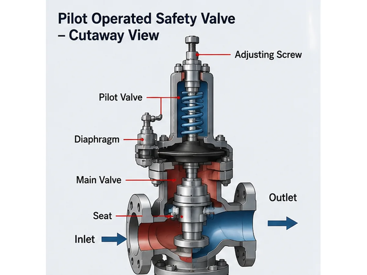
Illustrazione tecnica semplificata generata da IA; non è un disegno sezionale del produttore, un record di capacità certificato o un documento di approvazione del progetto.
Risposta rapida: Il rilevamento remoto può essere utile quando la pressione all'ingresso della valvola principale non rappresenta in modo affidabile la pressione dell'apparecchiatura protetta durante lo scenario di scarico principale. Il rischio chiave è che il pilota risponda alla pressione fornita attraverso la linea di rilevamento. Se quella linea è bloccata, perde, condensa, congela, è isolata in modo errato o collegata al punto sbagliato, la valvola installata potrebbe non comportarsi come la valvola collaudata in fabbrica.
Cosa significa rilevamento remoto in una valvola di sicurezza pilotata
In una disposizione tipica di rilevamento locale, il pilota riceve la pressione dall'area di ingresso della valvola principale o da una connessione vicino alla valvola. Ciò può essere accettabile quando la pressione di ingresso della valvola rappresenta in modo affidabile la pressione dell'apparecchiatura protetta nel caso di scarico prevalente.
In una disposizione di rilevamento remoto, il segnale di pressione viene prelevato da un punto remoto definito, come un bocchello del recipiente, una posizione del collettore o un altro punto di pressione approvato. Lo scopo non è rendere la valvola “più avanzata” per impostazione predefinita. Lo scopo è far sì che il pilota risponda alla pressione che dovrebbe controllare la funzione di protezione.
A valvola di sicurezza pilotata utilizza il circuito del pilota per controllare la pressione sul pistone, sulla cupola o sull'area operativa della valvola principale, a seconda del progetto. Se il pilota rileva la pressione da una posizione errata, la valvola principale può aprirsi o richiudersi in base a una pressione che non corrisponde all'apparecchiatura protetta.
Punto ingegneristico: il rilevamento remoto è una decisione di feedback della pressione. Deve essere valutato con lo scenario di scarico, il punto di pressione dell'apparecchiatura protetta, la perdita di carico in ingresso, il progetto del pilota, il comportamento del fluido e il controllo della manutenzione. Non deve essere specificato solo perché la valvola è pilotata.
| Articolo | Rilevamento locale | Rilevamento Remoto | Nota di ingegneria |
|---|---|---|---|
| Sorgente di pressione | Ingresso valvola principale o connessione pilota vicino alla valvola | Punto di pressione remoto selezionato | Deve rappresentare la pressione dell'apparecchiatura protetta nel caso di scarico prevalente |
| Vantaggio principale | Layout più semplice | Può rilevare un punto di pressione più rappresentativo in alcuni sistemi | Richiede la revisione del produttore e del sistema |
| Rischio principale | La pressione locale in ingresso potrebbe non rappresentare la pressione dell'apparecchiatura | La linea di rilevamento può ostruirsi, perdere, congelarsi o ritardare la risposta | Nessuna opzione sostituisce il calcolo dello scarico |
| Input per richiesta di offerta | Pressione in ingresso e connessione della valvola | Punto remoto, percorso della linea e accessori della linea | Includere foto e disegni per progetti di sostituzione |
Perché la linea di rilevamento può modificare il comportamento della valvola
La linea di rilevamento fa parte del sistema di controllo di una valvola di sicurezza pilotata. Una piccola linea può influenzare una grande valvola perché trasporta il segnale di pressione che indica al pilota quando attivarsi. Se il segnale viene ritardato, smorzato, bloccato, perde o viene prelevato dal punto sbagliato, la valvola principale potrebbe non rispondere come previsto.
Il principale rischio di selezione è presumere che la pressione di taratura certificata della valvola da sola dimostri la risposta installata dell'intero sistema. Una prova di taratura in officina può verificare la valvola in condizioni di prova, ma il sistema installato dipende anche dal fatto che il pilota riceva il corretto segnale di pressione in campo.
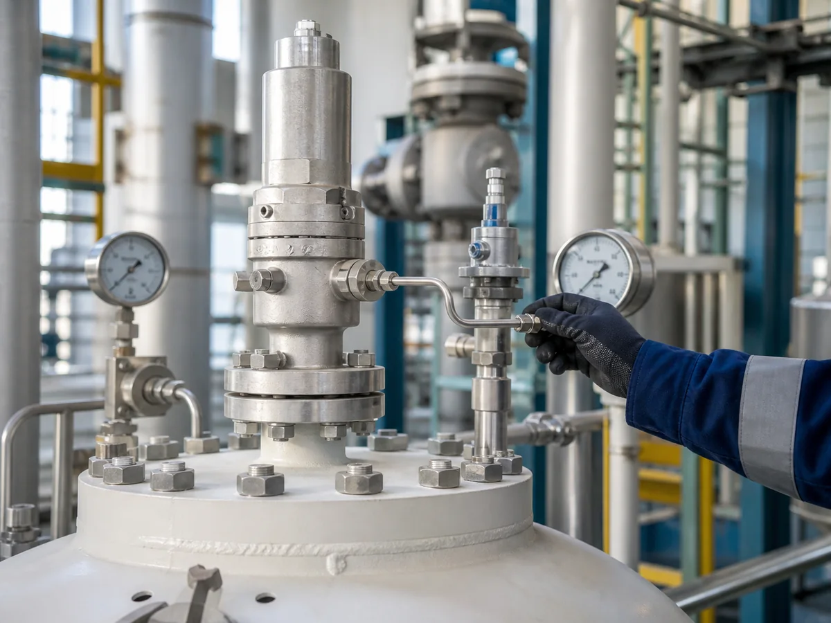
Immagine generata da IA per il contesto di installazione; verificare l'effettivo collegamento di rilevamento, il percorso dei tubi e le istruzioni del produttore per la valvola selezionata.
Pressione rilevata rispetto alla pressione dell'apparecchiatura protetta
L'apparecchiatura protetta può essere un recipiente in pressione, una caldaia, una linea di processo, lo scarico di un compressore, uno scambiatore di calore, uno skid o altro sistema in pressione. La pressione che conta per la protezione è quella al punto di controllo definito dallo scenario di scarico e dalla base di progettazione.
Se il pilota rileva una pressione inferiore a quella dell'apparecchiatura protetta durante il caso di scarico, l'apertura può essere ritardata. Se rileva una pressione instabile o non rappresentativa, la valvola può ciclare, sfarfallare, non richiudere correttamente o sembrare avere un problema al pilota quando il vero problema è il collegamento di rilevamento o la condizione della linea.
Ritardo di pressione e ritardo di risposta
Una linea di rilevamento remota può introdurre un ritardo di risposta se la linea è troppo lunga per il servizio, presenta restrizioni non necessarie, contiene sacche di liquido, è parzialmente ostruita o è collegata tramite raccordi non adatti. In servizio con gas pulito, il problema può essere minimo se la linea è corta, asciutta e correttamente instradata. In servizio con vapore condensante, gas sporco, servizio polimerizzante o condizioni ambientali di congelamento, lo stesso layout può diventare inaffidabile.
Effetto su apertura, stabilità e richiusura
Un rilevamento ostruito o ritardato può far sì che il pilota veda la pressione più tardi rispetto all'apparecchiatura protetta.
Perdite, vibrazioni o oscillazioni di pressione nella linea di rilevamento possono creare una risposta instabile del pilota.
Condensa, contaminazione o restrizioni nella linea possono rendere difficile diagnosticare il comportamento di richiusura solo dalla valvola principale.
Non utilizzare i dati delle prove in officina come unica prova del comportamento in installazione. Una prova di taratura può confermare la valvola in condizioni di prova, ma la risposta in campo dipende anche dal punto di rilevamento remoto, dalle condizioni della linea di rilevamento, dal sistema di ingresso, dalla contropressione allo scarico e dal fluido di servizio effettivo.
Quando può essere presa in considerazione la rilevazione remota
La rilevazione remota può essere presa in considerazione quando l'ingegnere necessita che il pilota rilevi la pressione in un punto che rappresenti meglio l'apparecchiatura protetta rispetto all'ingresso della valvola principale. Deve essere trattata come una configurazione progettata, non come un'opzione predefinita.
Preoccupazioni sulla perdita di carico in ingresso
Un motivo comune per valutare il rilevamento remoto è la preoccupazione per la perdita di carico in ingresso. Se il pilota rileva la pressione solo all'ingresso locale della valvola principale, e tale pressione locale è inferiore alla pressione dell'apparecchiatura protetta durante il flusso, il segnale del pilota potrebbe non rappresentare la condizione di pressione di governo.
Il rilevamento remoto può aiutare il pilota a ricevere la pressione dall'apparecchiatura protetta o da un altro punto approvato. Tuttavia, non elimina la necessità di verificare la perdita di carico in ingresso. La tubazione di ingresso deve comunque essere valutata perché una perdita eccessiva in ingresso può influire sulla capacità della valvola, sulla stabilità e sulle prestazioni del sistema. Per controlli più ampi sulla tubazione, utilizzare il guida all'installazione delle valvole di sicurezza.
Rilevamento remoto da ugello apparecchiatura o collettore
Alcuni sistemi possono richiedere che il segnale di pressione venga prelevato da un ugello del recipiente, da un collettore di processo o da un'altra posizione definita. Ciò può essere rilevante quando la valvola è fisicamente lontana dall'apparecchiatura o quando la disposizione delle tubazioni crea una differenza tra la pressione dell'apparecchiatura e la pressione locale all'ingresso della valvola.
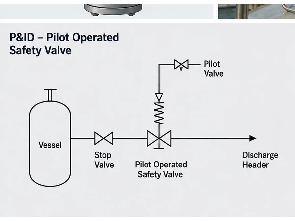
Illustrazione semplificata in stile P&ID generata da AI; non è un disegno di progetto, una registrazione di incidente o un documento di approvazione del produttore.
Situazioni di retrofit e sostituzione
Il rilevamento remoto viene spesso trascurato durante i lavori di sostituzione. Un acquirente può abbinare la dimensione nominale, la classe di flangiatura, la pressione di taratura e l'aspetto generale della valvola, ma non verificare il vecchio sistema di rilevamento, i tubi del pilota, i filtri, le restrizioni, gli scarichi, le valvole di isolamento o il tracciamento termico.
La sostituzione basata solo sull'aspetto o sulla targhetta è pericolosa. La scheda tecnica esistente, la targhetta, il P&ID, le foto dei tubi installati e qualsiasi registrazione di modifiche sul campo devono essere esaminati prima di selezionare una valvola di sicurezza pilotata sostitutiva.
| Condizione | Il rilevamento remoto può essere utile quando | Il rilevamento remoto non risolve | Dati da confermare |
|---|---|---|---|
| Tratto di ingresso lungo o restrittivo | La pressione all'ingresso della valvola locale potrebbe non rappresentare la pressione dell'apparecchiatura protetta | Perdita di carico eccessiva all'ingresso, scarso supporto delle tubazioni o percorso di scarico sottodimensionato | Percorso del flusso di scarico, perdita di pressione all'ingresso, P&ID e limiti del produttore |
| Punto di pressione remoto del serbatoio o della testata | Il punto di pressione di riferimento è fisicamente lontano dall'ingresso principale della valvola | Selezione errata del punto di rilevamento o comportamento non verificato della pressione nella testata | Apparecchiatura protetta, scenario di scarico e posizione della sorgente di pressione |
| Adeguamento o sostituzione | L'installazione esistente utilizza già una disposizione di rilevamento remoto approvata | Copiare l'aspetto della tubazione senza verificare il progetto della valvola pilota e il rischio di servizio | Targhetta, scheda tecnica, P&ID, foto, cronologia operativa e registri MOC |
Verifiche di progettazione della linea di rilevamento prima della richiesta di offerta
Prima della quotazione, la linea di rilevamento deve essere descritta come parte del requisito della valvola. La richiesta di offerta non deve limitarsi a indicare “valvola di sicurezza pilotata con rilevamento remoto”. Deve definire quale pressione viene rilevata, da dove proviene il segnale e quali rischi di servizio possono influenzare la linea.
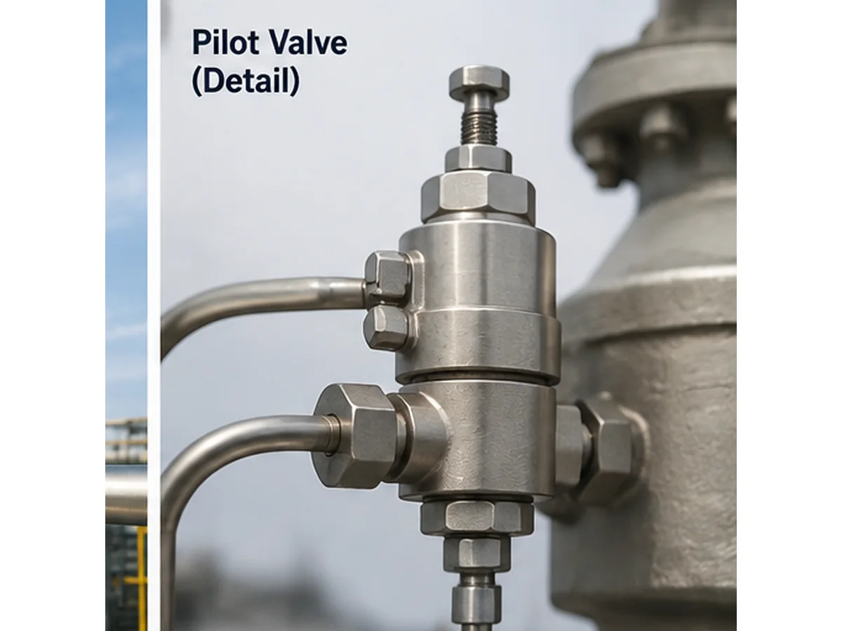
Primo piano tecnico generato da intelligenza artificiale; la corrispondenza nome-file-visivo è stata controllata negli attributi HTML alt, title e caption.
Punto di rilevamento e posizione di prelievo
La richiesta di offerta deve identificare il punto di rilevamento proposto. Questo può includere un ugello protetto dell'apparecchiatura, una connessione a monte del recipiente, una posizione sulla testata di processo, una connessione all'ingresso della valvola o un punto di connessione remota approvato dal produttore. La posizione di prelievo non deve creare un tratto morto, una tasca di liquido o una trappola di contaminazione. Deve inoltre evitare un punto di pressione non rappresentativo nella condizione di scarico prevalente.
Percorso del tubo, pendenza e protezione meccanica
Il percorso della linea di rilevamento deve essere breve e diretto quando possibile, ma il percorso effettivo deve anche considerare accessibilità, vibrazioni, movimento termico, drenaggio e protezione da danni meccanici. La linea non deve essere instradata dove può essere calpestata, piegata, surriscaldata, congelata o scollegata durante la manutenzione ordinaria.
Pendenza e drenaggio sono particolarmente importanti in servizio con vapore condensante, vapore, gas umido e miscele. Una linea che sembra accettabile su un disegno può creare un punto basso in campo. Quel punto basso può raccogliere liquido e ritardare la trasmissione della pressione al pilota.
Isolamento, scarico e accesso per manutenzione
Valvole di isolamento, scarichi, filtri e connessioni di prova possono essere richiesti in alcuni sistemi, ma creano anche rischi di guasto se selezionati in modo errato, lasciati chiusi, tappati o modificati. Se questi elementi sono consentiti dipende dal codice applicabile, dalla specifica di progetto, dai controlli di blocco in apertura, dalle procedure operative e dalle istruzioni del produttore.
Rischi specifici del fluido di processo
La linea di rilevamento deve essere verificata in base al fluido e alla fase effettivi: gas secco pulito, gas umido, vapore o vapore condensante, liquido, scarico bifase, servizio sporco o incrostante, servizio corrosivo, mezzi polimerizzanti o cristallizzanti e servizio esterno con gelo. Il solo grado del materiale non dimostra l'idoneità. La linea di rilevamento, i raccordi, le parti interne del pilota, le guarnizioni, i filtri e i componenti bagnati devono essere compatibili con il fluido, la temperatura e il piano di manutenzione. L'idoneità dei materiali deve considerare anche le sedi elastomeriche o le guarnizioni O-ring, i materiali delle guarnizioni, i tubi di piccolo diametro e i raccordi, le parti interne bagnate del pilota e l'ambiente della molla o della camera della molla, se applicabile.
| Condizione di servizio | Preoccupazione sulla linea di rilevamento remota | Verifica prima della richiesta di offerta | Non dare per scontato |
|---|---|---|---|
| Gas secco pulito | Integrità del segnale, perdite e vibrazioni | Percorso della linea, raccordi, supporto e connessione al pilota | Che qualsiasi disposizione di tubi di piccolo diametro sia accettabile |
| Vapore o vapore condensante | Tasca di condensa, perdita di calore, segnale ritardato | Pendenza, scarichi, tracciamento, isolamento e condizione di avviamento | Che una disposizione di rilevamento a gas secco possa essere riutilizzata |
| Servizio sporco, ceroso o polimerizzante | Restrizione, intasamento e contaminazione del pilota | Strategia di filtraggio, accesso per il lavaggio, compatibilità dei materiali e intervallo di manutenzione | Il telerilevamento risolverà il servizio sporco senza controllo di manutenzione |
| Servizio corrosivo | Degrado delle parti bagnate di tubo, raccordo, tenuta e pilota | Materiale bagnato, materiale della tenuta, ambiente della molla e sovrametallo di corrosione | Che il solo materiale del corpo dimostri la piena idoneità al servizio |
| Esposizione al gelo all'aperto | Blocco da ghiaccio e feedback di pressione errato | Temperatura ambiente, fonte d'acqua, tracciamento, isolamento e drenaggio | Che il solo isolamento prevenga tutti i guasti della linea di rilevamento |
Rischi comuni di guasto del rilevamento remoto
Il rilevamento remoto può migliorare la rappresentazione della pressione nella configurazione corretta, ma aggiunge una dipendenza dalla linea di controllo. Molti guasti del rilevamento remoto non sono evidenti dal corpo principale della valvola. Possono manifestarsi come instabilità del pilota, comportamento di apertura errato o perdite inspiegabili.
| Rischio di guasto | Effetto possibile | Controllo in campo | Dati necessari per la richiesta di preventivo (RFQ) |
|---|---|---|---|
| Linea di rilevamento bloccata | Risposta del pilota ritardata o assente | Ispezionare linea, raccordi, filtri e contaminazione | Rischio di fluido di processo, solidi, corrosione e incrostazioni |
| Raccordo o tubo che perde | Segnale di bassa pressione falso o instabilità | Controllare la tenuta di raccordi e tubazioni | Materiale del tubo, pressione, percorso e vibrazioni |
| Tasca di condensa | Risposta smorzata o ritardata | Verificare pendenza, punti bassi e scarichi | Fase del fluido di processo, temperatura e percorso della linea |
| Congelamento | Linea di segnale bloccata | Verificare esposizione, tracciamento e isolamento | Temperatura ambiente e rischio di condensa |
| Condizione di isolamento errata | Funzione di protezione disabilitata o distorta | Confermare la posizione della valvola e il controllo di blocco in apertura | Filosofia e procedura di isolamento |
| Punto di prelievo errato | Il pilota rileva una pressione non rappresentativa | Confrontare il P&ID con la disposizione in campo | Attrezzatura protetta e scenario di sfioro |
Ostruzione e contaminazione
Una linea di rilevamento ostruita può impedire al pilota di ricevere il segnale di pressione corretto. L'ostruzione può derivare da sporco, prodotti di corrosione, solidi di processo, cera, polimeri, ghiaccio, condensa o detriti di installazione. Un guasto comune in campo si verifica quando il corpo della valvola principale è installato correttamente, ma la piccola connessione di rilevamento si restringe nel tempo.
Perdite e feedback di pressione falso
Un raccordo che perde, un tubo incrinato, una connessione a compressione allentata o una linea di piccolo diametro danneggiata possono ridurre o distorcere il segnale di pressione. A seconda del design del pilota e delle condizioni di servizio, una perdita può causare instabilità, apertura ritardata, richiusura errata o ripetuti reclami di manutenzione.
Condensa, congelamento e sacche di liquido
La condensa è uno dei rischi più importanti nel servizio con vapore o gas umido. Una linea di rilevamento che crea un punto basso può raccogliere liquido. Questo liquido può ritardare il segnale di pressione, smorzare la risposta del pilota, congelare con il freddo o introdurre corrosione.
Condizione di isolamento o bypass errata
Una valvola di isolamento lasciata chiusa, parzialmente chiusa o bloccata in modo errato può disabilitare o distorcere la funzione di rilevamento. Una connessione di prova o una disposizione di bypass può creare un rischio simile se non è controllata dalla procedura operativa. Il rilevamento remoto dovrebbe quindi essere documentato nel P&ID, nelle istruzioni operative e nella lista di controllo della manutenzione.
| Sintomo Osservato | Possibile causa della linea di rilevamento | Controllare prima di sostituire la valvola |
|---|---|---|
| La valvola sembra aprirsi in ritardo | Linea bloccata, sacca di condensa, punto di rilevamento errato o trasmissione della pressione ritardata | Verificare il punto di prelievo della pressione, la pulizia della linea, la pendenza e le condizioni di servizio |
| Instabilità ripetuta del pilota | Raccordo che perde, vibrazioni, tubazione non supportata o sorgente di pressione instabile | Ispezionare i supporti dei tubi, i raccordi, la sorgente di pressione e le modifiche in campo |
| Comportamento di richiusura inatteso | Sacchetto di liquido, contaminazione, condizione di scarico errata o restrizione del circuito pilota | Controllare scarichi, punti bassi, condizioni del filtro e registro di manutenzione del pilota |
| Comportamento diverso dopo la sostituzione | Vecchio schema di rilevamento copiato in modo incompleto o nuovo design del pilota non adattato al layout | Confrontare vecchi e nuovi fogli dati, modello del pilota, layout dei tubi e istruzioni del produttore |
| Nessun danno evidente alla valvola principale ma la risposta rimane errata | La linea di rilevamento o la disposizione di isolamento possono fuorviare il pilota | Rivedere P&ID, stato di blocco aperto, connessione di prova, bypass e foto di campo |
Il rilevamento remoto non sostituisce la revisione della capacità e del sistema
Il rilevamento remoto modifica il punto in cui il pilota riceve il segnale di pressione. Non dimostra che la valvola selezionata abbia una capacità di scarico sufficiente, che l'installazione sia accettabile o che il sistema di uscita possa gestire lo scarico.
Confine ingegneristico: La pressione di taratura non è la capacità, e la dimensione della connessione non è la capacità di scarico certificata. Una valvola con la stessa dimensione di ingresso e uscita può avere una capacità certificata o documentata diversa a seconda del design, dell'orifizio, del coefficiente, della base del fluido e della norma applicabile.
La capacità dipende ancora dal carico di scarico richiesto
Una valvola di sicurezza pilotata può essere tarata correttamente ma risultare comunque inadatta se la capacità di scarico richiesta, la base del fluido, la temperatura di scarico, la contropressione o l'orifizio selezionato sono errati. Utilizzare la dimensionamento della valvola di sicurezza e alla capacità di sfioro certificata guida quando il progetto necessita di una base di capacità più chiara.
I controlli del sistema di ingresso e uscita rimangono applicabili
Il rilevamento remoto può aiutare il pilota a percepire un punto di pressione più rappresentativo, ma la tubazione di ingresso influisce comunque sul flusso verso la valvola. Una perdita di carico eccessiva all'ingresso può contribuire a instabilità e problemi di capacità. Anche la contropressione all'uscita rimane importante. La contropressione sovrapposta e la contropressione generata devono essere esaminate separatamente. Per una spiegazione più ampia della contropressione sovrapposta, della contropressione generata e dei limiti di selezione del soffietto bilanciato, consultare la Contropressione e soffietto guida.
I dati del produttore e il codice di progetto rimangono determinanti
La selezione finale dipende dal design della valvola scelto, dai dati del produttore, dall'edizione applicabile della norma, dalle specifiche di progetto e dai requisiti normativi locali. La richiesta di offerta deve indicare se il progetto segue ASME, API, ISO, EN, GB o un altro quadro normativo, e l'edizione adottata deve essere verificata per il progetto. Per una traduzione più ampia delle norme, consultare API 520 dimensionamento valvole di sicurezza e API 521 sistemi di sfioro pressione.
Cosa può aiutare il rilevamento remoto
- Migliore rappresentazione della pressione quando il punto di rilevamento approvato differisce dall'ingresso principale della valvola.
- Riferimento di risposta del pilota più chiaro in alcuni layout con problemi di perdita di carico.
- Risoluzione dei problemi migliorata quando il percorso di rilevamento è documentato e accessibile.
Cosa il rilevamento remoto non può sostituire
- Calcolo del carico di scarico e della capacità richiesta.
- Verifica della capacità certificata o documentata.
- Revisione della perdita di carico in ingresso, della contropressione allo scarico e del sistema di scarico.
- Approvazione del produttore per la configurazione del pilota selezionata.
Scenari di ingegneria compositi per la revisione del telerilevamento
I seguenti scenari sono esempi di ingegneria compositi a scopo di formazione. Non sono casi cliente, rapporti di incidente o prove delle prestazioni di uno specifico prodotto ZOBAI.
Scenario 1: Pressione di ingresso locale fuorviante
Un recipiente in pressione scarica in una valvola di sicurezza pilotata attraverso una tubazione in cui la perdita di carico in ingresso può diventare significativa durante il flusso di scarico. Il telerilevamento può aiutare il pilota a ricevere un segnale di pressione più rappresentativo, ma la valvola e la tubazione di ingresso devono comunque essere esaminate come sistema. Il controllo preventivo consiste nel definire il punto di pressione dell'apparecchiatura protetta, calcolare il caso di scarico e confermare la disposizione del rilevamento con il produttore della valvola.
Scenario 2: Condensa nella linea di rilevamento
Una linea di rilevamento per servizio di vapore umido è instradata con un punto basso. La condensa si accumula e attenua il segnale del pilota. Il sintomo sul campo può sembrare instabilità del pilota, ma la revisione deve includere il percorso, la pendenza, gli scarichi, il tracciamento, le condizioni di avviamento e la fase del fluido. L'azione correttiva non è semplicemente sostituire il pilota; la disposizione della linea di rilevamento deve essere corretta o controllata.
Scenario 3: Sostituzione senza verifica della linea
Un acquirente per sostituzione abbina la dimensione della flangia e la pressione di taratura, ma non fornisce il P&ID o le foto della linea di rilevamento. Il rischio non è solo la mancata corrispondenza dimensionale; il requisito del pilota e il percorso di rilevamento possono essere diversi. Il passo di prevenzione è rivedere la targhetta, il foglio dati, la tubazione del pilota esistente, lo scenario di scarico e qualsiasi modifica sul campo prima di selezionare la valvola sostitutiva.
RFQ e lista di controllo per la manutenzione
Una buona RFQ per una valvola di sicurezza pilotata con rilevamento remoto dovrebbe descrivere il servizio e la disposizione del rilevamento. L'acquirente non dovrebbe fare affidamento su una breve descrizione come “uguale alla vecchia valvola” o “valvola pilotata con rilevamento remoto”.”
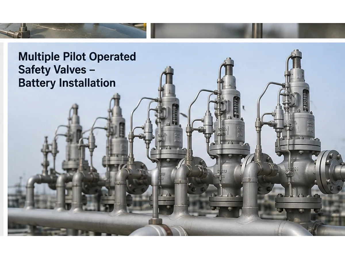
Immagine generata da IA relativa al contesto di installazione; non dimostra un progetto reale, capacità certificata, risultato di prova o installazione del cliente.
| Categoria dati | Informazioni richieste | Perché è Importante |
|---|---|---|
| Apparecchiatura protetta | Vaso, caldaia, linea, compressore, skid o altro sistema | Definisce la sorgente di pressione da proteggere |
| Scenario di sfioro | Uscita bloccata, incendio, rottura del tubo, guasto del regolatore o altro caso | Definisce il carico governante e la condizione di pressione |
| Fluido e fase | Gas, vapore, liquido, bifase, sporco, corrosivo o condensante | Influisce sull'affidabilità della linea di rilevamento e sul progetto della valvola |
| Dati di pressione | Pressione operativa, MAWP/pressione di progetto e pressione di taratura | Previene la confusione sulla terminologia della pressione |
| Capacità | Capacità di sfioro richiesta e base di calcolo della capacità | Previene la selezione basata sulla dimensione della connessione |
| Temperatura | Temperatura operativa e di sfioro | Influisce su materiale, guarnizioni e rischio di condensa/congelamento |
| Contropressione | Contropressione sovrapposta e accumulata | Influisce sulla selezione e sulla stabilità della valvola |
| Linea di rilevamento | Punto, percorso, pendenza, lunghezza, isolamento, scarico e tracciamento | Affidabilità del segnale di pilotaggio |
| Documenti | Scheda tecnica, P&ID, targhetta, foto e requisiti normativi | Consente la sostituzione e la revisione tecnica |
Suggerimento per la revisione della sostituzione: per una POSV esistente, inviare foto ravvicinate della valvola pilota, dei tubi, del punto di prelievo del segnale, delle valvole di isolamento, degli scarichi, dei filtri, della targhetta e delle tubazioni di ingresso/uscita circostanti. Una valvola che corrisponde alle dimensioni e alla pressione di taratura potrebbe comunque essere errata se il circuito pilota o il percorso di rilevamento remoto non sono compatibili.
Inviare i dettagli del rilevamento remoto prima della selezione della POSV
Inviare l'apparecchiatura protetta, lo scenario di scarico, il fluido e la fase, la pressione di esercizio, la MAWP o la pressione di progetto, la pressione di taratura, la capacità di scarico richiesta, la temperatura di scarico, la contropressione, la connessione di ingresso/uscita, il punto di rilevamento remoto, il percorso della linea di rilevamento, i materiali e le norme applicabili.
- Per i nuovi progetti, includere lo scenario di scarico, i dati di processo e il punto di rilevamento proposto.
- Per i progetti di sostituzione, includere la targhetta della vecchia valvola, la scheda tecnica, le foto installate e il P&ID.
- Per la risoluzione dei problemi, includere sintomi, cronologia operativa, azioni di manutenzione e eventuali registrazioni di modifiche sul campo.
Note su norme e riferimenti tecnici
La selezione delle valvole di sicurezza pilotate con rilevamento remoto deve essere verificata in base al codice di progetto adottato, alle istruzioni del produttore e all'edizione della norma applicabile. Le seguenti fonti ufficiali sono utilizzate solo come riferimento e non implicano che ogni prodotto ZOBAI sia automaticamente dotato di ogni certificazione o marchio di conformità.
- ISO 4126-4:2013 — pagina ISO ufficiale per le valvole di sicurezza pilotate.
- API 520 Parte I — pagina API ufficiale per il contesto di dimensionamento e selezione.
- Norma API 521 — pagina API ufficiale per i sistemi di sfioro e depressurizzazione.
- ASME BPVC Sezione XIII, 2025 — pagina ASME ufficiale per le regole sulla protezione dalla sovrappressione.
FAQ
Che cos'è il rilevamento remoto su una valvola di sicurezza pilotata?
Il telerilevamento significa che il pilota riceve la pressione da un punto remoto selezionato invece di rilevare la pressione solo all'ingresso della valvola principale o nelle sue vicinanze. L'obiettivo è far sì che il pilota risponda a un punto di pressione che rappresenti meglio l'apparecchiatura protetta.
Il telerilevamento è sempre migliore del rilevamento locale?
No. La telelettura può essere utile in alcuni layout, ma aggiunge rischi alla linea di rilevamento come ostruzione, perdite, condensa, congelamento, isolamento errato e ritardo di risposta. Deve essere valutata per il servizio specifico e il progetto della valvola.
Il telerilevamento può risolvere la perdita di pressione in ingresso?
Il telerilevamento può aiutare il pilota a ricevere un segnale di pressione più rappresentativo, ma non elimina la necessità di verificare la perdita di pressione all'ingresso. È comunque necessario controllare la tubazione di ingresso, la capacità, la stabilità e i limiti del produttore.
Cosa succede se la linea di rilevamento è bloccata?
Una linea di rilevamento ostruita può impedire al pilota di ricevere la pressione reale dell'apparecchiatura protetta. Ciò può causare apertura ritardata, risposta errata, instabilità o mancato funzionamento come previsto.
La linea di rilevamento deve essere dotata di una valvola di intercettazione?
Dipende dal codice applicabile, dalle specifiche di progetto, dalle procedure operative, dal controllo di blocco in apertura e dalle istruzioni del produttore. Una valvola di intercettazione può supportare la manutenzione, ma se controllata in modo errato può disattivare o compromettere la funzione di protezione.
Posso sostituire una POSV scegliendo la stessa dimensione e pressione di taratura?
No. Le dimensioni di connessione e la pressione di taratura non sono sufficienti. La verifica per la sostituzione deve includere la capacità certificata o documentata, la configurazione del pilota, il tracciato della linea di rilevamento, il fluido di processo, la temperatura, la contropressione, l'installazione e i documenti applicabili.
Quali dati devo inviare prima di richiedere un preventivo?
Inviare l'apparecchiatura protetta, lo scenario di scarico, il fluido di processo e la fase, la pressione di esercizio, la MAWP/pressione di progetto, la pressione di taratura, la capacità di scarico richiesta, la temperatura di scarico, la contropressione, le connessioni di ingresso/uscita, il punto di rilevamento e la disposizione della linea di rilevamento.
Cosa controllare durante la manutenzione prima di attribuire il problema alla valvola pilota?
Prima di concludere che la valvola pilota stessa sia la causa principale, la manutenzione deve verificare il punto di prelievo del segnale, l'eventuale ostruzione della linea, le perdite, i punti bassi, la condensa, l'esposizione al gelo, la posizione della valvola di isolamento, il supporto dei tubi, i filtri, gli scarichi e qualsiasi modifica apportata in campo.






Commenti
Kesari Alloys
L'enfasi sul fatto che la linea di rilevamento faccia parte della funzione di protezione è fondamentale. È facile trascurare come una linea ostruita o con perdite possa fuorviare la risoluzione dei problemi. Mi chiedo se potrebbe approfondire come vari materiali e tecniche di installazione per la linea di rilevamento possano influire sulla sua affidabilità, soprattutto in condizioni con potenziale di condensa o ostruzioni.