
Инженерные решения для предохранительных клапанов с пилотным управлением: Дистанционный отбор давления: проектирование линии и риски отказов Дистанционный отбор давления в предохранительном клапане с пилотным управлением означает, что пилот получает импульс давления из выбранной точки, удаленной от входа основного клапана. Это может помочь пилоту реагировать на точку давления, которая лучше отражает защищаемое оборудование, но также делает линию отбора частью функции защиты. Заблокированная, пропускающая, замерзшая, с конденсатом или неправильно изолированная линия отбора может задержать открытие, вызвать нестабильную реакцию или затруднить диагностику. Дистанционный отбор давления не является стандартным улучшением и не заменяет расчет пропускной способности, проверку потерь давления на входе, проверку противодавления или одобрение производителя. Перед запросом котировки подтвердите защищаемое оборудование, сценарий сброса, среду и фазу, рабочее давление, MAWP или расчетное давление, давление настройки, требуемую пропускную способность, температуру сброса, противодавление и предлагаемую схему линии отбора.

Инженерные решения для предохранительных клапанов с пилотным управлением
Дистанционное управление предохранительными клапанами с пилотным управлением: проектирование линии и риски отказов
Дистанционный отбор давления в предохранительном клапане с пилотным управлением означает, что пилот получает импульс давления из выбранной точки, удаленной от входа основного клапана. Это может помочь пилоту реагировать на точку давления, которая лучше отражает защищаемое оборудование, но также делает линию отбора частью функции защиты. Заблокированная, пропускающая, замерзшая, с конденсатом или неправильно изолированная линия отбора может задержать открытие, вызвать нестабильную реакцию или затруднить диагностику. Дистанционный отбор давления не является стандартным улучшением и не заменяет расчет пропускной способности, проверку потерь давления на входе, проверку противодавления или одобрение производителя. Перед запросом котировки подтвердите защищаемое оборудование, сценарий сброса, среду и фазу, рабочее давление, MAWP или расчетное давление, давление настройки, требуемую пропускную способность, температуру сброса, противодавление и предлагаемую схему линии отбора.
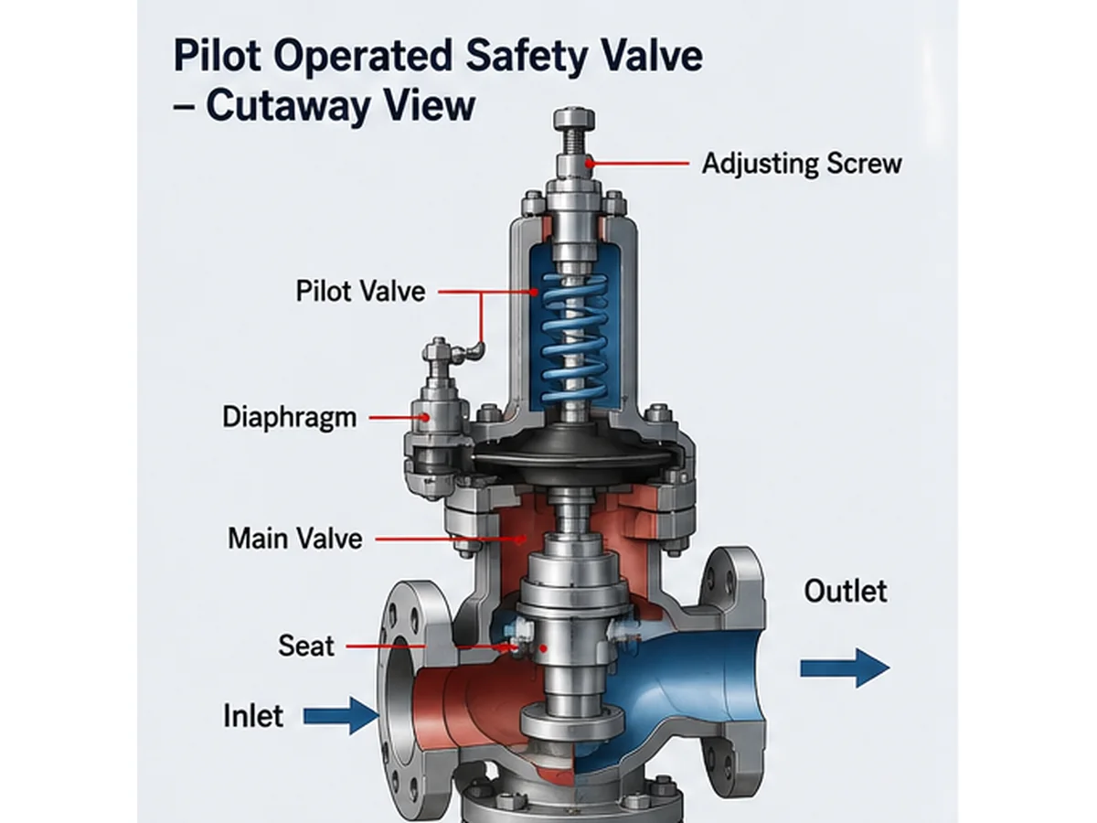
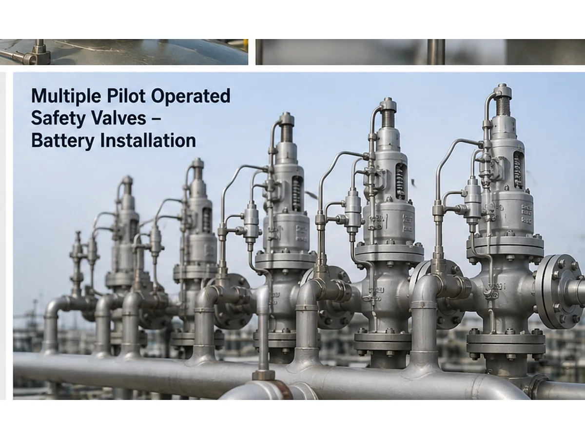
Упрощенная инженерная иллюстрация, созданная ИИ; не является заводским чертежом в разрезе, сертифицированной записью пропускной способности или проектным документом.
Краткий ответ: Дистанционный отбор давления может быть полезен, когда давление на входе основного клапана не отражает надежно давление защищаемого оборудования во время основного сценария сброса. Ключевой риск заключается в том, что пилот реагирует на давление, подаваемое через линию отбора. Если эта линия заблокирована, пропускает, имеет конденсат, замерзла, неправильно изолирована или подключена к неправильной точке, установленный клапан может вести себя не так, как клапан, испытанный на заводе.
Что означает дистанционный отбор давления в предохранительном клапане с пилотным управлением
При типовой схеме с местным отбором давления пилот получает давление из области входного патрубка главного клапана или из соединения вблизи клапана. Это может быть приемлемо, когда давление на входе клапана достоверно отражает давление защищаемого оборудования в расчетном режиме сброса.
При дистанционном отборе давления сигнал давления отбирается из заданной удаленной точки, например, из штуцера сосуда, участка коллектора или другой утвержденной точки отбора давления. Цель не в том, чтобы сделать клапан “более совершенным” по умолчанию. Цель — заставить пилот реагировать на давление, которое должно управлять функцией защиты.
A предохранительный клапан с пилотным управлением использует пилотную схему для управления давлением над поршнем, куполом или рабочей областью главного клапана, в зависимости от конструкции. Если пилот воспринимает давление из неправильной точки, главный клапан может открыться или закрыться под действием давления, не соответствующего защищаемому оборудованию.
Инженерный момент: дистанционный отбор давления — это решение по обратной связи по давлению. Его следует рассматривать с учетом сценария сброса, точки отбора давления защищаемого оборудования, потерь давления на входе, конструкции пилота, поведения рабочей среды и контроля обслуживания. Его не следует указывать только потому, что клапан имеет пилотное управление.
| Элемент | Местный отбор давления | Дистанционное зондирование | Инженерная заметка |
|---|---|---|---|
| Источник давления | Вход главного клапана или соединение пилота вблизи клапана | Выбранная удаленная точка отбора давления | Должна отражать давление защищаемого оборудования в расчетном режиме сброса |
| Основное преимущество | Более простая компоновка | Может воспринимать более репрезентативную точку давления в некоторых системах | Требует проверки производителем и системой |
| Основной риск | Локальное давление на входе может не отражать давление в оборудовании | Импульсная линия может засориться, дать течь, замерзнуть или задержать реакцию | Ни один из вариантов не заменяет расчет сброса давления |
| Ввод данных для запроса коммерческого предложения | Давление на входе клапана и соединение | Удаленная точка, трасса линии и аксессуары линии | Включите фотографии и чертежи для проектов замены |
Почему импульсная линия может изменить поведение клапана
Импульсная линия является частью системы управления предохранительного клапана с пилотным управлением. Небольшая линия может влиять на большой клапан, поскольку она передает сигнал давления, который сообщает пилоту, когда срабатывать. Если этот сигнал задерживается, демпфируется, блокируется, протекает или снимается из неправильной точки, главный клапан может не сработать должным образом.
Основной риск при выборе заключается в предположении, что сертифицированное давление настройки клапана само по себе подтверждает установленную реакцию всей системы. Испытание давления настройки на заводе может проверить клапан в условиях испытания, но установленная система также зависит от того, получает ли пилот правильный сигнал давления на объекте.
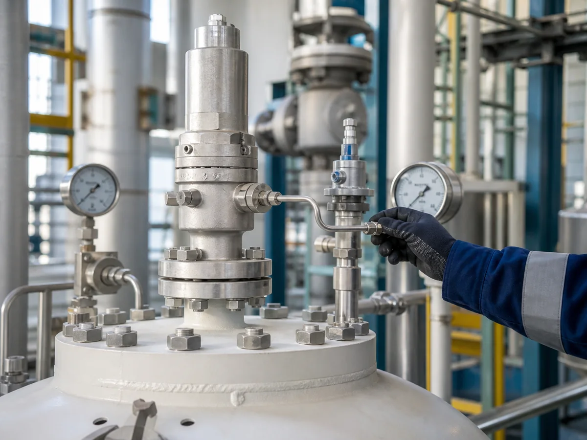
ИИ-сгенерированное изображение для контекста установки; уточните фактическое подключение датчика, трассировку трубки и инструкции производителя для выбранного клапана.
Контролируемое давление по сравнению с давлением защищаемого оборудования
Защищаемое оборудование может быть сосудом под давлением, котлом, технологической линией, нагнетанием компрессора, теплообменником, блоком (skid) или другой системой под давлением. Давление, которое имеет значение для защиты, — это давление в контрольной точке, определенной сценарием сброса и проектной основой.
Если пилот воспринимает давление ниже, чем в защищаемом оборудовании во время сброса, открытие может быть задержано. Если он воспринимает нестабильное или нерепрезентативное давление, клапан может колебаться, дребезжать, не закрываться полностью или казаться неисправным, когда реальная проблема заключается в подключении датчика или состоянии линии.
Задержка давления и запаздывание реакции
Выносная линия датчика может создавать задержку реакции, если линия слишком длинна для данной среды, имеет лишние сужения, содержит жидкие пробки, частично забита или подключена через неподходящие фитинги. В среде чистого газа проблема может быть незначительной, если линия короткая, сухая и правильно проложена. В конденсирующемся паре, загрязненном газе, полимеризующейся среде или при замерзающих температурах окружающей среды та же схема может стать ненадежной.
Влияние на открытие, стабильность и посадку
Заблокированное или задержанное восприятие давления может привести к тому, что пилот увидит давление позже, чем защищаемое оборудование.
Утечки, вибрация или колебания давления в линии датчика могут вызвать нестабильную реакцию пилота.
Конденсат, загрязнения или ограничения в линии могут затруднить диагностику поведения при посадке только по основному клапану.
Не используйте данные заводских испытаний как единственное доказательство поведения в установленных условиях. Испытание на давление открытия может подтвердить работу клапана в условиях испытания, но реакция в полевых условиях также зависит от точки отбора давления, состояния линии датчика, входной системы, выходного противодавления и фактической рабочей среды.
Когда может рассматриваться дистанционное измерение давления
Дистанционное измерение давления может рассматриваться, когда инженеру необходимо, чтобы пилот воспринимал давление в точке, которая лучше отражает состояние защищаемого оборудования, чем вход основного клапана. Это следует рассматривать как инженерную конфигурацию, а не стандартный вариант.
Опасения по поводу потери давления на входе
Частой причиной рассмотрения дистанционного отбора импульса является опасение потери давления на входе. Если пилот воспринимает давление только на местном входе основного клапана, и это местное давление ниже давления защищаемого оборудования во время потока, сигнал пилота может не отражать фактическое состояние регулируемого давления.
Дистанционный отбор импульса может помочь пилоту получать давление от защищаемого оборудования или другой утвержденной точки. Однако это не отменяет необходимости проверки потери давления на входе. Входной трубопровод все равно должен быть оценен, поскольку чрезмерные потери на входе могут повлиять на пропускную способность клапана, стабильность и производительность системы. Для более широких проверок трубопровода используйте руководство по установке предохранительного клапана.
Дистанционный отбор от сопла оборудования или коллектора
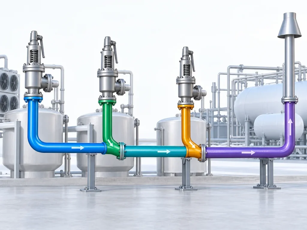
В некоторых системах может потребоваться отбор сигнала давления от сопла сосуда, технологического коллектора или другого определенного места. Это может быть актуально, когда клапан физически расположен далеко от оборудования или когда схема трубопровода создает разницу между давлением оборудования и местным давлением на входе клапана.
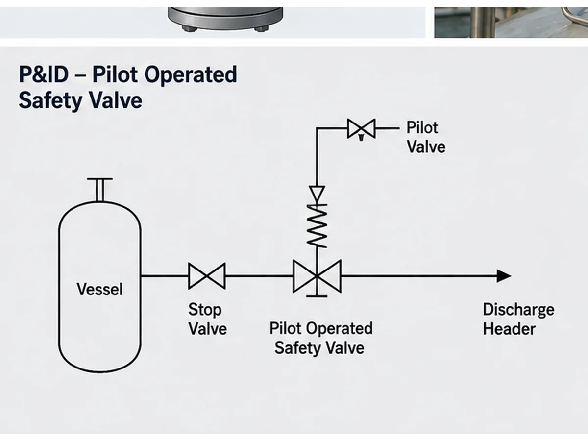
Упрощенная иллюстрация в стиле P&ID, созданная ИИ; не является проектным чертежом, записью инцидента или документом одобрения производителя.
Ситуации модернизации и замены
Дистанционный отбор импульса часто упускается из виду при замене. Покупатель может подобрать клапан по номинальному размеру, классу фланца, давлению настройки и общему внешнему виду, но не проверить старую схему отбора импульса, трубки пилота, фильтры, ограничители, дренажи, запорные клапаны или тепловое сопровождение.
Замена только по внешнему виду или размеру с шильдика небезопасна. Перед выбором замены предохранительного клапана с пилотным управлением необходимо изучить существующий паспорт, шильдик, P&ID, фотографии установленных трубок и любые записи о полевых модификациях.
| Условие | Дистанционный отбор импульса может помочь, когда | Дистанционный отбор импульса не решает | Данные для подтверждения |
|---|---|---|---|
| Длинный или ограничивающий входной участок | Местное давление на входе клапана может не отражать давление защищаемого оборудования | Чрезмерные потери на входе, плохая опора трубопровода или заниженное проходное сечение линии сброса | Путь сброса, потери давления на входе, P&ID и ограничения производителя |
| Удаленная точка давления в сосуде или коллекторе | Контрольная точка давления физически удалена от основного входа клапана | Неверный выбор точки отбора импульса или непроверенное поведение давления в коллекторе | Защищаемое оборудование, сценарий сброса и местонахождение источника давления |
| Модернизация или замена | Существующая установка уже использует одобренную схему с дистанционным отбором импульса | Копирование внешнего вида трубки без проверки конструкции пилота и рисков эксплуатации | Заводская табличка, технический паспорт, P&ID, фотографии, история эксплуатации и записи MOC |
Проверка проекта импульсной линии до запроса котировки
До запроса котировки импульсная линия должна быть описана как часть требований к клапану. В запросе котировки не должно быть просто указано “предохранительный клапан с пилотным управлением с дистанционным отбором импульса”. Необходимо определить, какое давление измеряется, откуда поступает сигнал и какие эксплуатационные риски могут повлиять на линию.
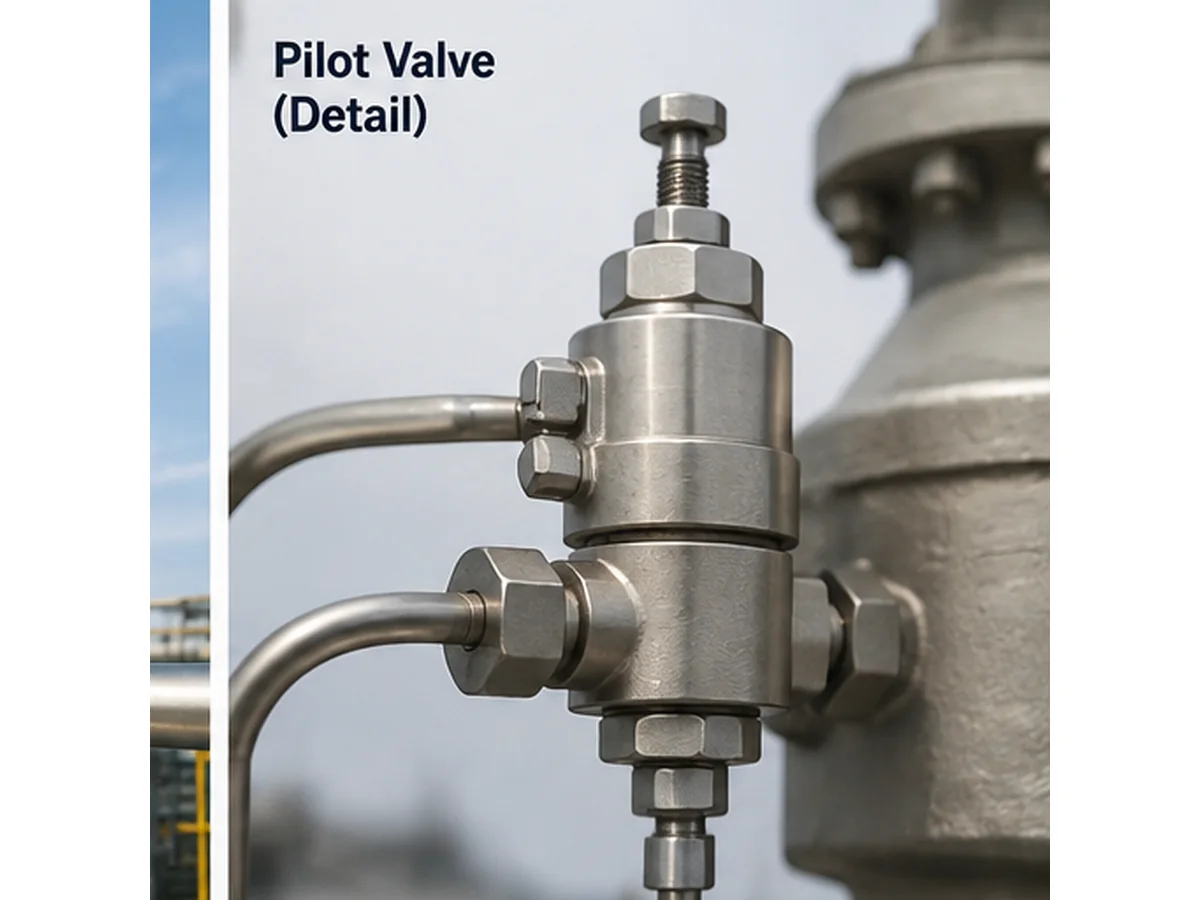
Техническое изображение, созданное ИИ; формулировка, соответствующая имени файла, контролируется в HTML-атрибутах alt, title и caption.
Точка отбора импульса и место отбора
В запросе котировки должна быть указана предлагаемая точка отбора импульса. Это может быть защищенный штуцер оборудования, соединение на входе сосуда, место на технологическом коллекторе, входное соединение клапана или одобренное производителем дистанционное место подключения. Место отбора не должно создавать тупиковую зону, карман для жидкости или ловушку для загрязнений. Также следует избегать точки давления, которая не является репрезентативной для расчетного случая сброса.
Трасса трубки, уклон и механическая защита
Трасса импульсной линии должна быть короткой и прямой, где это практически возможно, но фактическая трасса также должна учитывать доступность, вибрацию, тепловое расширение, дренаж и защиту от механических повреждений. Линия не должна прокладываться в местах, где на нее можно наступить, где она может быть изогнута, перегрета, замерзнуть или отсоединена во время планового технического обслуживания.
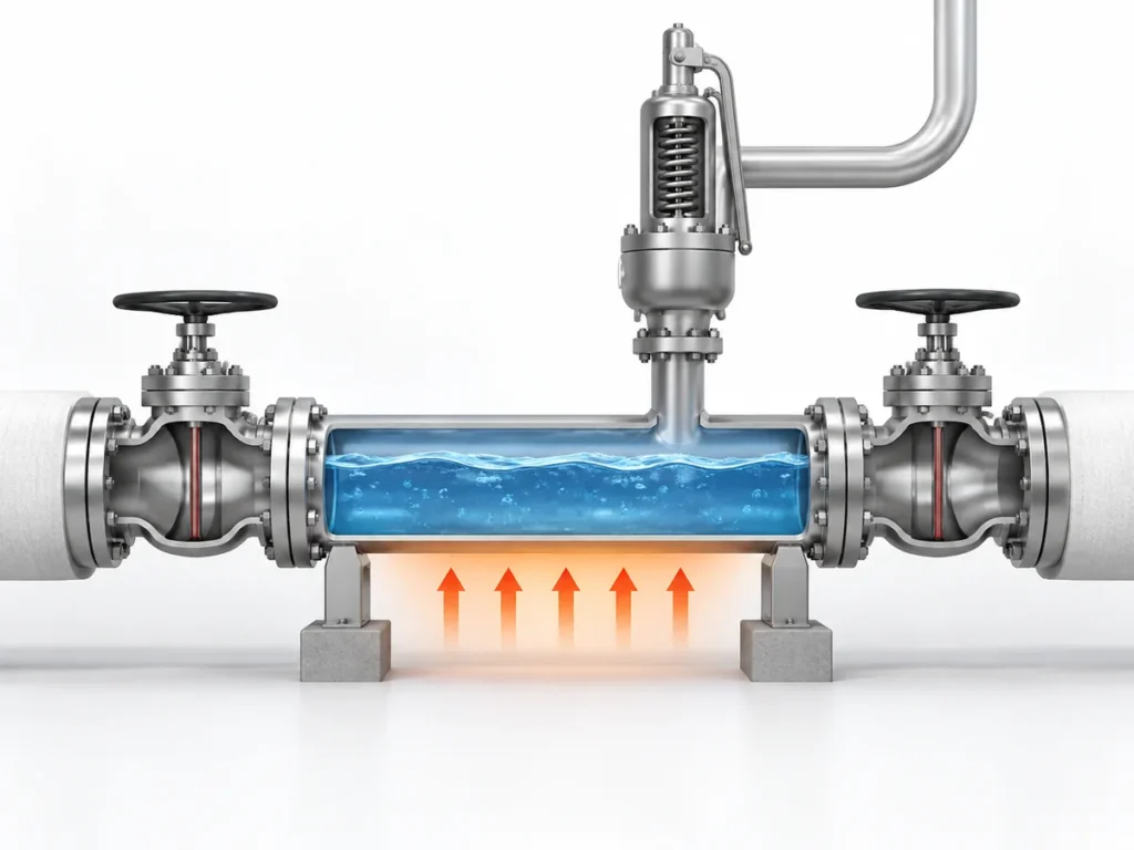
Уклон и дренаж особенно важны при работе с конденсирующимся паром, паром, влажным газом и смешанными средами. Линия, которая выглядит приемлемой на чертеже, может создать низкую точку в полевых условиях. Эта низкая точка может собирать жидкость и задерживать передачу давления к пилоту.
Запорная арматура, дренаж и доступ для обслуживания
В некоторых системах могут потребоваться запорные клапаны, дренажи, фильтры и контрольные соединения, но они также создают риски отказов, если они неправильно выбраны, оставлены закрытыми, заглушены или изменены. Допустимость этих элементов зависит от применимых норм, проектной спецификации, мер по предотвращению закрытия, эксплуатационных процедур и инструкций производителя.
Риски, связанные с конкретной средой
Линия отбора импульса должна быть проверена на соответствие фактической среде и фазе: чистый сухой газ, влажный газ, пар или конденсирующийся пар, жидкость, двухфазный сброс, загрязненная или засоряющаяся среда, коррозионная среда, полимеризующиеся или кристаллизующиеся среды и замерзающая среда при наружной установке. Только марка материала не подтверждает пригодность. Линия отбора импульса, фитинги, внутренние детали пилота, уплотнения, фильтры и смачиваемые компоненты должны быть совместимы со средой, температурой и планом технического обслуживания. Пригодность материалов также должна учитывать эластомерные седла или уплотнительные кольца, материалы прокладок, трубки малого диаметра и фитинги, внутренние смачиваемые детали пилота и, при необходимости, среду пружины или пружинной камеры.
| Условие эксплуатации | Вопрос по линии дистанционного отбора импульса | Проверить перед запросом предложения | Не предполагайте |
|---|---|---|---|
| Чистый сухой газ | Целостность сигнала, утечки и вибрация | Трасса линии, фитинги, опоры и подключение к пилоту | Что любая компоновка трубок малого диаметра приемлема |
| Пар или конденсирующийся пар | Конденсатный карман, потери тепла, задержка сигнала | Уклон, дренажи, обогрев, изоляция и условия запуска | Что схема отбора сухого газа может быть использована повторно |
| Загрязненная, воскообразная или полимеризующаяся среда | Ограничение, засорение и загрязнение пилота | Стратегия фильтрации, доступ для промывки, совместимость материалов и интервал технического обслуживания | Что дистанционное снятие давления решит проблему загрязненной среды без контроля обслуживания |
| Коррозионностойкая среда | Деградация деталей трубки, фитинга, уплотнения и пилота, контактирующих со средой | Материал контактирующих со средой деталей, материал уплотнений, условия работы пружины и припуск на коррозию | Что материал корпуса сам по себе подтверждает полную пригодность для эксплуатации |
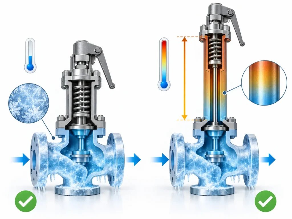
| Воздействие наружного замерзания | Ледяная пробка и ложная обратная связь по давлению | Температура окружающей среды, источник воды, обогрев, изоляция и дренаж | Что изоляция сама по себе предотвращает все отказы линии снятия давления |
Типовые риски при дистанционном снятии давления
Дистанционное снятие давления может улучшить представление давления при правильной компоновке, но добавляет зависимость от линии управления. Многие отказы дистанционного снятия давления не очевидны по основному корпусу клапана. Они могут проявляться как нестабильность пилота, неправильное поведение при открытии или необъяснимая утечка.
| Риск отказа | Возможное влияние | Полевая проверка | Необходимые данные для запроса коммерческого предложения |
|---|---|---|---|
| Заблокированная линия снятия давления | Задержка или отсутствие реакции пилота | Проверьте линию, фитинги, фильтры и загрязнения | Риск, связанный со средой, твердыми частицами, коррозией и загрязнением |
| Утечка в фитинге или трубке | Ложный сигнал низкого давления или нестабильность | Проверьте фитинги и трубки на утечки | Материал трубки, давление, трассировка и вибрация |
| Конденсатный карман | Демпфированная или замедленная реакция | Проверьте уклон, нижние точки и дренажи | Фаза среды, температура и трассировка линии |
| Замерзание | Заблокированная импульсная линия | Проверьте воздействие окружающей среды, обогрев и изоляцию | Температура окружающей среды и риск образования конденсата |
| Неправильное состояние изоляции | Функция защиты отключена или искажена | Подтвердите положение клапана и управление с фиксацией в открытом положении | Философия и процедура изоляции |
| Неправильная точка отбора | Пилот воспринимает нерепрезентативное давление | Сравните P&ID с фактической компоновкой оборудования | Защищаемое оборудование и сценарий сброса давления |
Закупорка и загрязнение
Закупоренная импульсная линия может препятствовать получению пилотом правильного сигнала давления. Закупорка может быть вызвана грязью, продуктами коррозии, твердыми частицами технологической среды, воском, полимером, льдом, конденсатом или монтажным мусором. Частая неисправность на объекте возникает, когда корпус основного клапана установлен правильно, но небольшое импульсное соединение со временем сужается.
Утечка и ложная обратная связь по давлению
Протекающее соединение, треснувшая трубка, ослабленное обжимное соединение или поврежденная линия малого диаметра могут снизить или исказить сигнал давления. В зависимости от конструкции пилота и условий эксплуатации утечка может вызывать нестабильность, задержку открытия, неправильную посадку или повторяющиеся жалобы на обслуживание.
Конденсат, замерзание и жидкостные карманы
Конденсат является одним из наиболее важных рисков при работе с паром или влажным газом. Импульсная линия, создающая нижнюю точку, может накапливать жидкость. Эта жидкость может задерживать сигнал давления, демпфировать реакцию пилота, замерзать в холодную погоду или вызывать коррозию.
Неправильное состояние запорной или байпасной арматуры
Запорный клапан, оставленный закрытым, частично закрытым или неправильно зафиксированным, может отключить или исказить функцию измерения. Тестовое соединение или байпасная схема могут создать аналогичный риск, если они не контролируются рабочей процедурой. Поэтому дистанционный отбор давления должен быть задокументирован в P&ID, инструкциях по эксплуатации и контрольном списке технического обслуживания.
| Наблюдаемый симптом | Возможная причина в импульсной линии | Проверьте перед заменой клапана |
|---|---|---|
| Клапан, по-видимому, открывается поздно | Забитая линия, карман конденсата, неправильная точка отбора или задержка передачи давления | Проверьте точку отбора давления, чистоту линии, уклон и условия эксплуатации |
| Повторяющаяся нестабильность пилота | Утечка в фитинге, вибрация, незакреплённая трубопроводная обвязка или нестабильный источник давления | Проверьте опоры трубопровода, фитинги, источник давления и изменения, внесённые на объекте |
| Неожиданное поведение при повторной посадке | Жидкостная пробка, загрязнение, неправильное дренирование или ограничение в импульсной линии | Проверьте дренажи, нижние точки, состояние фильтра и журнал обслуживания пилота |
| Иное поведение после замены | Старая схема отбора импульса скопирована не полностью или новая конструкция пилота не соответствует компоновке | Сравните старые и новые паспорта, модель пилота, схему трубопроводов и инструкции производителя |
| Нет явного повреждения основного клапана, но реакция остается неправильной | Импульсная линия или запорная арматура могут вводить пилот в заблуждение | Проверьте P&ID, состояние блокировки, тестовое подключение, байпас и фотографии с объекта |
Дистанционный отбор импульса не заменяет проверку пропускной способности и системы
Дистанционный отбор импульса изменяет точку, где пилот получает сигнал давления. Это не доказывает, что выбранный клапан имеет достаточную пропускную способность, что монтаж приемлем или что выходная система может выдержать сброс.
Инженерные ограничения: Давление настройки — это не пропускная способность, а размер присоединения — не сертифицированная пропускная способность. Клапан с одинаковыми входным и выходным размерами может иметь разную сертифицированную или документированную пропускную способность в зависимости от конструкции, проходного сечения, коэффициента, среды и применимого стандарта.
Пропускная способность по-прежнему зависит от требуемой нагрузки сброса
Предохранительный клапан с пилотным управлением может быть правильно настроен, но все равно не подходить, если требуемая пропускная способность сброса, характеристики среды, температура сброса, противодавление или выбранное проходное сечение неверны. Используйте расчету предохранительных клапанов и сертифицированной пропускной способности руководство, когда проекту требуется более четкое обоснование пропускной способности.
Проверки входного и выходного трубопроводов по-прежнему применяются
Дистанционное считывание давления может помочь пилоту воспринимать более репрезентативную точку давления, но входной трубопровод по-прежнему влияет на поток в клапан. Чрезмерные потери на входе могут способствовать нестабильности и проблемам с пропускной способностью. Противодавление на выходе также остается важным. Наложенное противодавление и создаваемое противодавление должны рассматриваться отдельно. Для более подробного объяснения наложенного противодавления, создаваемого противодавления и границ выбора сильфонного уравновешивания, ознакомьтесь с противодавление и сильфон справочник.
Данные производителя и проектные нормы остаются определяющими
Окончательный выбор зависит от выбранной конструкции клапана, данных производителя, применимой редакции стандарта, проектной спецификации и местных нормативных требований. В запросе котировки (RFQ) должно быть указано, соответствует ли проект ASME, API, ISO, EN, GB или другой системе, а принятая редакция должна быть проверена для проекта. Для более широкого перевода стандартов ознакомьтесь с Расчет предохранительных клапанов по API 520 и Системы сброса давления API 521.
Что может помочь дистанционное считывание давления
- Более точное представление давления, когда утвержденная точка отбора отличается от входа основного клапана.
- Более четкая опорная точка реакции пилота в некоторых схемах с проблемами перепада давления.
- Улучшенное устранение неисправностей, когда линия считывания давления задокументирована и доступна.
Что не может заменить дистанционное считывание давления
- Расчет нагрузки сброса и требуемой пропускной способности.
- Проверка сертифицированной или документированной пропускной способности.
- Анализ потерь давления на входе, противодавления на выходе и системы сброса.
- Согласование с производителем выбранной конфигурации пилота.
Комплексные инженерные сценарии для анализа дистанционного зондирования
Нижеприведенные сценарии являются комплексными инженерными примерами для обучения. Они не являются случаями из практики заказчиков, отчетами об авариях или доказательством конкретных характеристик продукции ZOBAI.
Сценарий 1: Вводящее в заблуждение местное давление на входе
Сосуд под давлением сбрасывает среду в предохранительный клапан с пилотным управлением через трубопровод, где потери давления на входе могут стать значительными во время потока сброса. Дистанционное зондирование может помочь пилоту получать более репрезентативный сигнал давления, но клапан и входной трубопровод все равно должны рассматриваться как единая система. Профилактическим мероприятием является определение точки давления защищаемого оборудования, расчет случая сброса и подтверждение схемы зондирования с производителем клапана.
Сценарий 2: Конденсат в линии зондирования
Линия зондирования для влажного пара проложена с нижней точкой. Там собирается конденсат и демпфирует сигнал пилота. Симптом на объекте может выглядеть как нестабильность пилота, но анализ должен включать трассу, уклон, дренажи, обогрев, условия пуска и фазу среды. Корректирующее действие не заключается в простой замене пилота; компоновка линии зондирования должна быть исправлена или контролируема.
Сценарий 3: Замена без проверки линии
Покупатель, осуществляющий замену, подбирает размер фланца и давление настройки, но не предоставляет P&ID или фотографии линии зондирования. Риск заключается не только в несоответствии размеров; требования к пилоту и путь зондирования могут отличаться. Профилактическим шагом является анализ шильдика, технических данных, существующей трубной обвязки пилота, сценария сброса и любых полевых модификаций перед выбором заменяющего клапана.
Запрос котировки и контрольный перечень технического обслуживания
Хороший запрос котировки для предохранительного клапана с пилотным управлением и дистанционным датчиком должен описывать условия эксплуатации и схему подключения датчика. Покупателю не следует полагаться на краткое описание, такое как “как старый клапан” или “пилотный клапан с дистанционным датчиком”.”
ИИ-сгенерированное изображение контекста установки; оно не подтверждает реальный проект, сертифицированную пропускную способность, результаты испытаний или установку у заказчика.
| Категория данных | Обязательная информация | Почему это важно |
|---|---|---|
| Защищаемое оборудование | Сосуд, котел, трубопровод, компрессор, блок или другая система | Определяет источник давления, который необходимо защитить |
| Сценарий сброса давления | Заблокированный выход, пожар, разрыв трубки, отказ регулятора или другой случай | Определяет расчетный режим и условия давления |
| Среда и фаза | Газ, пар, жидкость, двухфазная среда, загрязненная, коррозионная или конденсирующаяся среда | Влияет на надежность линии датчика и конструкцию клапана |
| Данные по давлению | Рабочее давление, максимальное допустимое рабочее давление (MAWP)/расчетное давление и давление настройки | Предотвращает путаницу в терминологии давления |
| Производительность | Требуемая производительность сброса и основа для расчета производительности | Исключает выбор по размеру присоединения |
| Температура | Рабочая и температура сброса | Влияет на материал, уплотнения и риск образования конденсата/замерзания |
| Противодавление | Наложенное и нарастающее противодавление | Влияет на выбор клапана и стабильность |
| Линия импульса | Точка, трасса, уклон, длина, изоляция, дренаж и обогрев | Определяет надежность сигнала пилота |
| Документы | Технический паспорт, P&ID, шильдик, фотографии и требования стандартов | Обеспечивает замену и техническую экспертизу |
Совет по экспертизе замены: для существующего POSV отправьте крупные фотографии пилотного клапана, трубопровода, точки отбора импульса, запорной арматуры, дренажей, фильтров, шильдика и окружающих входного/выходного трубопроводов. Клапан, соответствующий по размеру и давлению настройки, может все равно не подойти, если пилотная схема или путь дистанционного отбора импульса несовместимы.
Отправьте данные о дистанционном отборе импульса до выбора POSV
Укажите защищаемое оборудование, сценарий сброса, среду и фазу, рабочее давление, MAWP или расчетное давление, давление настройки, требуемую пропускную способность, температуру сброса, противодавление, входное/выходное соединение, точку дистанционного отбора импульса, трассу линии отбора импульса, материалы и применимые стандарты.
- Для новых проектов укажите сценарий сброса, технологические данные и предлагаемую точку отбора импульса.
- Для проектов замены укажите шильдик старого клапана, технический паспорт, фотографии установки и P&ID.
- Для устранения неисправностей укажите симптомы, историю эксплуатации, выполненные работы по обслуживанию и записи о любых полевых модификациях.
Стандарты и технические справочные материалы
Выбор предохранительного клапана с дистанционным управлением и пилотным управлением должен быть проверен на соответствие принятому проектному кодексу, инструкциям производителя и действующей редакции стандарта. Нижеуказанные официальные источники используются только в качестве справочных направлений и не подразумевают, что каждое изделие ZOBAI автоматически имеет все сертификаты или знаки соответствия.
- ISO 4126-4:2013 — официальная страница ISO по предохранительным клапанам с пилотным управлением.
- API 520 Часть I — официальная страница API по расчету и выбору.
- Стандарт API 521 — официальная страница API по системам сброса давления и депрессуризации.
- ASME BPVC Раздел XIII, 2025 — официальная страница ASME по правилам защиты от превышения давления.
Часто задаваемые вопросы
Что такое дистанционное управление на предохранительном клапане с пилотным управлением?
Дистанционный отбор давления означает, что пилот получает давление из выбранной удаленной точки, а не только воспринимает давление на входе основного клапана или вблизи него. Цель — обеспечить реакцию пилота на точку давления, которая лучше отражает состояние защищаемого оборудования.
Всегда ли дистанционное зондирование лучше локального?
Нет. Дистанционное считывание давления может быть полезно в некоторых компоновках, но оно добавляет риски, связанные с импульсной линией, такие как засорение, утечка, конденсат, замерзание, неправильная изоляция и задержка срабатывания. Это должно быть рассмотрено для конкретной среды и конструкции клапана.
Можно ли решить проблему потери давления на входе с помощью дистанционного зондирования?
Дистанционное считывание давления может помочь пилоту получать более репрезентативный сигнал давления, но оно не отменяет необходимости проверки потерь давления на входе. Входной трубопровод, пропускная способность, стабильность и ограничения производителя по-прежнему должны быть проверены.
Что произойдет, если импульсная линия будет засорена?
Забитая импульсная линия может препятствовать передаче пилоту фактического давления в защищаемом оборудовании. Это может привести к задержке открытия, неправильной реакции, нестабильности или отказу в срабатывании.
Должен ли импульсный трубопровод иметь запорный клапан?
Это зависит от применимого кодекса, проектной спецификации, процедуры эксплуатации, контроля блокировки в открытом положении и инструкции производителя. Запорный клапан может облегчить техническое обслуживание, но при неправильном управлении он может отключить или исказить функцию защиты.
Можно ли заменить ПООК, подобрав его по размеру и давлению настройки?
Нет. Только размера присоединения и давления настройки недостаточно. Проверка замены должна включать сертифицированную или документально подтверждённую пропускную способность, конфигурацию пилота, схему импульсных линий, рабочую среду, температуру, противодавление, условия монтажа и применимые документы.
Какие данные необходимо отправить перед запросом цены?
Укажите защищаемое оборудование, сценарий сброса давления, рабочую среду и фазу, рабочее давление, MAWP/расчетное давление, давление настройки, требуемую пропускную способность при сбросе, температуру сброса, противодавление, присоединения на входе/выходе, точку отбора импульса и схему импульсной линии.
Что следует проверить при техническом обслуживании, прежде чем считать причиной неисправности пилотный клапан?
При техническом обслуживании перед выводом о том, что основной причиной является сам пилотный клапан, следует проверить точку отбора импульса, засорение линии, утечки, нижние точки, конденсат, воздействие замерзания, положение запорного клапана, опоры трубопровода, фильтры, дренажи и любые изменения, внесенные на объекте.

Комментарии
Kesari Alloys
Акцент на том, что импульсная линия является частью функции защиты, имеет решающее значение. Легко упустить из виду, как засоренная или пропускающая линия может ввести в заблуждение при поиске неисправностей. Интересно, могли бы вы подробнее рассказать о том, как различные материалы и методы монтажа импульсной линии могут влиять на ее надежность, особенно в условиях возможной конденсации или засорения.