
Pilotgesteuertes Sicherheitsventil Engineering Fernabtastung bei pilotgesteuerten Sicherheitsventilen: Leitungsauslegung und Ausfallrisiken Fernabtastung bei einem pilotgesteuerten Sicherheitsventil bedeutet, dass der Pilot sein Drucksignal von einem ausgewählten Druckpunkt entfernt vom Hauptventileinlass erhält. Dies kann dem Piloten helfen, auf einen Druckpunkt zu reagieren, der die geschützte Ausrüstung besser repräsentiert, macht aber auch die Messleitung zu einem Teil der Schutzfunktion. Eine blockierte, leckende, eingefrorene, kondensierte oder falsch isolierte Messleitung kann das Öffnen verzögern, instabile Reaktionen verursachen oder die Fehlersuche in die Irre führen. Fernabtastung ist kein Standard-Upgrade und ersetzt nicht die Auslegung der Abblasleistung, die Überprüfung des Einlassdruckverlusts, die Überprüfung des Gegendrucks oder die Freigabe durch den Hersteller. Vor der Angebotserstellung sind die geschützte Ausrüstung, das Entlastungsszenario, Medium und Phase, Betriebsdruck, MAWP oder Auslegungsdruck, Ansprechdruck, erforderliche Abblaskapazität, Abblasetemperatur, Gegendruck und die vorgeschlagene Messleitungsanordnung zu bestätigen.

Pilotgesteuertes Sicherheitsventil Engineering
Fernauslösung für pilotgesteuerte Sicherheitsventile: Leitungsauslegung und Ausfallrisiken
Fernabtastung bei einem pilotgesteuerten Sicherheitsventil bedeutet, dass der Pilot sein Drucksignal von einem ausgewählten Druckpunkt entfernt vom Hauptventileinlass erhält. Dies kann dem Piloten helfen, auf einen Druckpunkt zu reagieren, der die geschützte Ausrüstung besser repräsentiert, macht aber auch die Messleitung zu einem Teil der Schutzfunktion. Eine blockierte, leckende, eingefrorene, kondensierte oder falsch isolierte Messleitung kann das Öffnen verzögern, instabile Reaktionen verursachen oder die Fehlersuche in die Irre führen. Fernabtastung ist kein Standard-Upgrade und ersetzt nicht die Auslegung der Abblasleistung, die Überprüfung des Einlassdruckverlusts, die Überprüfung des Gegendrucks oder die Freigabe durch den Hersteller. Vor der Angebotserstellung sind die geschützte Ausrüstung, das Entlastungsszenario, Medium und Phase, Betriebsdruck, MAWP oder Auslegungsdruck, Ansprechdruck, erforderliche Abblaskapazität, Abblasetemperatur, Gegendruck und die vorgeschlagene Messleitungsanordnung zu bestätigen.
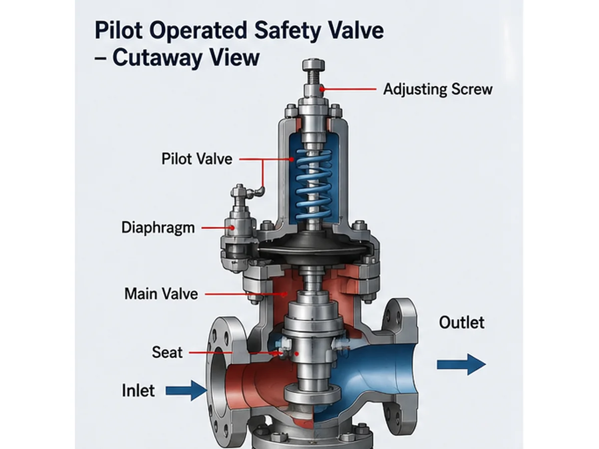
KI-generierte vereinfachte technische Abbildung; keine Herstellerschnittzeichnung, kein zertifizierter Kapazitätsnachweis und kein Projektfreigabedokument.
Schnelle Antwort: Fernabtastung kann sinnvoll sein, wenn der Einlassdruck des Hauptventils den Druck der geschützten Ausrüstung während des maßgeblichen Entlastungsszenarios nicht zuverlässig repräsentiert. Das Hauptrisiko besteht darin, dass der Pilot auf den Druck reagiert, der über die Messleitung geliefert wird. Wenn diese Leitung blockiert, leck, kondensiert, eingefroren, falsch isoliert oder am falschen Punkt angeschlossen ist, kann sich das installierte Ventil anders verhalten als das im Werk geprüfte Ventil.
Was Fernabtastung bei einem pilotgesteuerten Sicherheitsventil bedeutet
Bei einer typischen lokalen Abtastanordnung erhält der Pilot den Druck aus dem Einlassbereich des Hauptventils oder aus einer Verbindung in der Nähe des Ventils. Dies kann akzeptabel sein, wenn der Einlassdruck des Ventils zuverlässig den Druck der geschützten Ausrüstung im maßgebenden Entlastungsfall darstellt.
Bei einer Fernabtastanordnung wird das Drucksignal von einem definierten entfernten Punkt bezogen, z. B. von einem Behälterstutzen, einer Kopfleitung oder einem anderen zugelassenen Druckpunkt. Der Zweck besteht nicht darin, das Ventil standardmäßig “fortschrittlicher” zu machen. Der Zweck besteht darin, den Pilot auf den Druck reagieren zu lassen, der die Schutzfunktion steuern soll.
A Pilotgesteuertes Sicherheitsventil nutzt den Pilotkreis, um den Druck über dem Hauptventilkolben, der Dom- oder Wirkfläche zu steuern, je nach Ausführung. Wenn der Pilot den Druck von der falschen Stelle erfasst, kann das Hauptventil basierend auf einem Druck öffnen oder wieder schließen, der nicht der geschützten Ausrüstung entspricht.
Konstruktionspunkt: Fernabtastung ist eine Druckrückkopplungsentscheidung. Sie sollte im Zusammenhang mit dem Entlastungsszenario, dem Druckpunkt der geschützten Ausrüstung, dem Einlassdruckverlust, der Pilotausführung, dem Mediumverhalten und der Wartungskontrolle überprüft werden. Sie sollte nicht nur deshalb spezifiziert werden, weil das Ventil pilotgesteuert ist.
| Artikel | Lokale Abtastung | Fernabfrage | Technische Anmerkung |
|---|---|---|---|
| Druckquelle | Hauptventileinlass oder Pilotanschluss in der Nähe des Ventils | Ausgewählter entfernter Druckpunkt | Muss den Druck der geschützten Ausrüstung im maßgebenden Entlastungsfall darstellen |
| Hauptvorteil | Einfachere Anordnung | Kann in manchen Systemen einen repräsentativeren Druckpunkt erfassen | Erfordert Prüfung durch Hersteller und System |
| Hauptrisiko | Lokaler Einlassdruck entspricht möglicherweise nicht dem Gerätedruck | Die Messleitung kann blockieren, lecken, einfrieren oder die Reaktion verzögern | Keine Option ersetzt die Berechnung der Entlastung |
| Angebotsanfrage-Eingabe | Ventileinlassdruck und -anschluss | Entfernter Punkt, Leitungsführung und Leitungszubehör | Fotos und Zeichnungen für Ersatzprojekte beifügen |
Warum die Messleitung das Ventilverhalten verändern kann
Die Messleitung ist Teil des Steuerungssystems eines pilotgesteuerten Sicherheitsventils. Eine kleine Leitung kann ein großes Ventil beeinflussen, da sie das Drucksignal überträgt, das dem Piloten mitteilt, wann er auslösen soll. Wenn dieses Signal verzögert, gedämpft, blockiert, undicht ist oder vom falschen Punkt abgenommen wird, kann das Hauptventil möglicherweise nicht wie vorgesehen reagieren.
Das Hauptauswahlrisiko besteht darin, anzunehmen, dass der zertifizierte Einstelldruck des Ventils allein die installierte Reaktion des gesamten Systems beweist. Ein Einstelldrucktest im Werk kann das Ventil unter Testbedingungen verifizieren, aber das installierte System hängt auch davon ab, ob der Pilot das korrekte Felddrucksignal erhält.
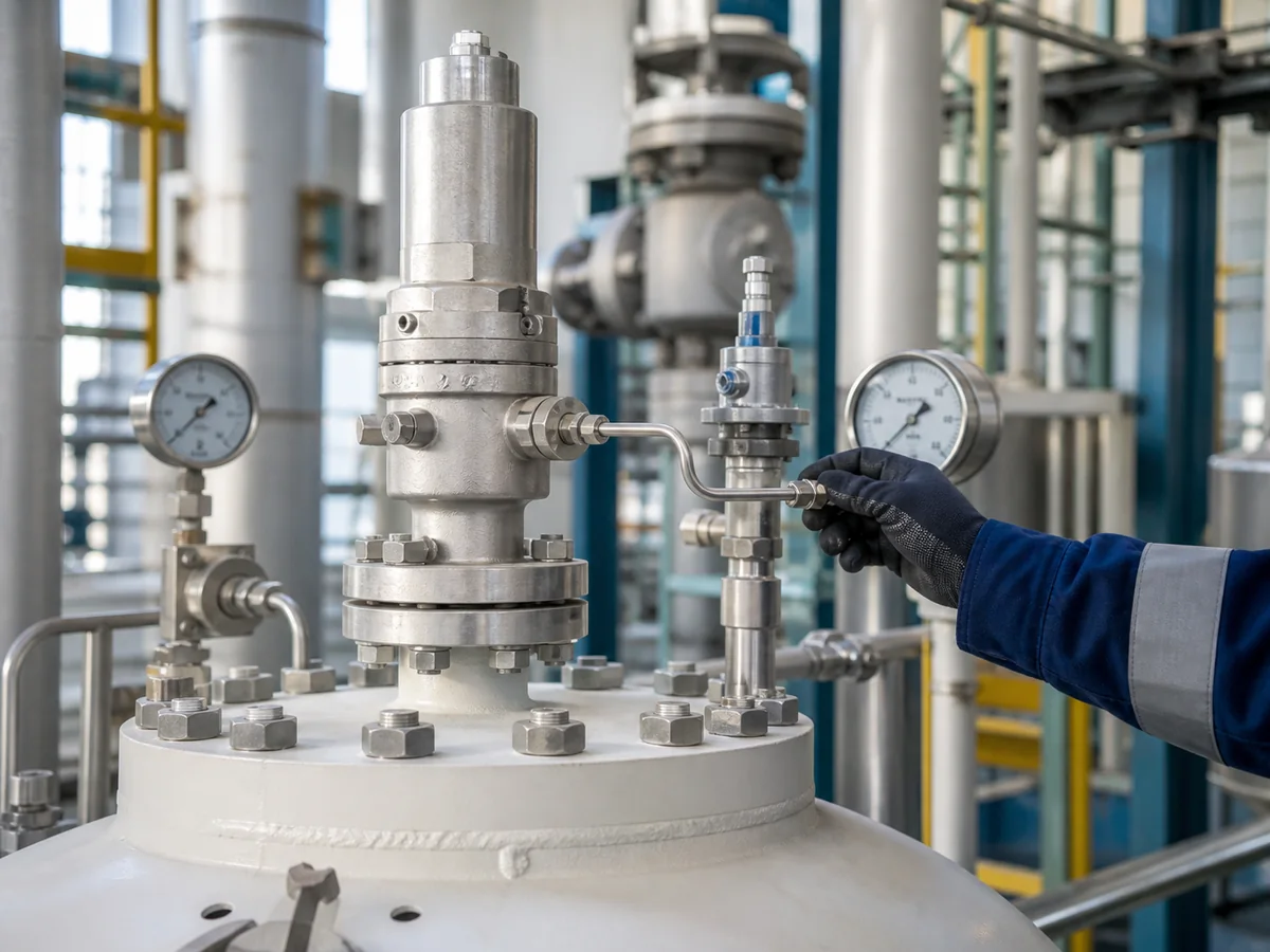
KI-generierte Darstellung des Einbaukontexts; bestätigen Sie die tatsächliche Messanschlussverbindung, die Leitungsführung und die Herstelleranweisungen für das ausgewählte Ventil.
Gemessener Druck vs. Druck des geschützten Geräts
Das geschützte Gerät kann ein Druckbehälter, ein Kessel, eine Prozessleitung, ein Verdichterauslass, ein Wärmetauscher, ein Skid oder ein anderes Drucksystem sein. Der für den Schutz maßgebliche Druck ist der Druck am Kontrollpunkt, der durch das Entlastungsszenario und die Auslegungsbasis definiert ist.
Wenn der Pilot während des Entlastungsfalls einen niedrigeren Druck als das geschützte Gerät misst, kann sich das Öffnen verzögern. Wenn er einen instabilen oder nicht repräsentativen Druck misst, kann das Ventil zyklisch arbeiten, flattern, nicht sauber schließen oder ein Pilotproblem vortäuschen, obwohl die eigentliche Ursache in der Messanschlussverbindung oder der Leitungsbeschaffenheit liegt.
Druckverzögerung und Ansprechverzögerung
Eine entfernte Messleitung kann eine Ansprechverzögerung verursachen, wenn die Leitung für den Betrieb zu lang ist, unnötige Einschränkungen aufweist, Flüssigkeitsansammlungen enthält, teilweise blockiert ist oder über ungeeignete Fittings angeschlossen ist. Bei sauberem Gas kann das Problem gering sein, wenn die Leitung kurz, trocken und korrekt verlegt ist. Bei kondensierendem Dampf, schmutzigem Gas, polymerisierendem Betrieb oder gefrierenden Umgebungsbedingungen kann dieselbe Anordnung unzuverlässig werden.
Auswirkung auf Öffnung, Stabilität und Wiedereinsetzen
Eine blockierte oder verzögerte Messung kann dazu führen, dass der Pilot den Druck später erkennt als das geschützte Gerät.
Leckagen, Vibrationen oder Druckschwingungen in der Messleitung können eine instabile Pilotreaktion verursachen.
Kondensat, Verunreinigungen oder Leitungseinschränkungen können das Wiedereinsetzverhalten erschweren, wenn es nur am Hauptventil diagnostiziert wird.
Verwenden Sie keine Prüfstandsdaten als alleinigen Nachweis für das Verhalten im eingebauten Zustand. Ein Ansprechdrucktest kann das Ventil unter Prüfbedingungen bestätigen, aber das Feldverhalten hängt auch von der entfernten Messstelle, dem Zustand der Messleitung, dem Einlasssystem, dem Auslassgegendruck und dem tatsächlichen Betriebsmedium ab.
Wann Fernmessung in Betracht gezogen werden kann
Fernmessung kann in Betracht gezogen werden, wenn der Ingenieur benötigt, dass der Pilot den Druck an einem Punkt erfasst, der die geschützte Anlage besser repräsentiert als der Haupteinlass des Ventils. Dies sollte als technisch ausgelegte Konfiguration behandelt werden, nicht als Standardoption.
Bedenken zum Druckverlust am Einlass
Ein häufiger Grund, eine Fernmessung in Betracht zu ziehen, ist die Sorge um den Druckverlust am Einlass. Wenn der Pilot nur am lokalen Haupteinlass des Ventils misst und dieser lokale Druck während des Durchflusses niedriger ist als der Druck der geschützten Ausrüstung, kann das Pilotsignal den maßgeblichen Druckzustand nicht repräsentieren.
Eine Fernmessung kann dem Piloten helfen, den Druck von der geschützten Ausrüstung oder einem anderen zugelassenen Punkt zu erhalten. Sie ersetzt jedoch nicht die Notwendigkeit, den Druckverlust am Einlass zu überprüfen. Die Einlassleitung muss weiterhin bewertet werden, da ein übermäßiger Einlassverlust die Kapazität, Stabilität und Systemleistung des Ventils beeinträchtigen kann. Für umfassendere Rohrleitungsprüfungen verwenden Sie die Installationsanleitung für Sicherheitsventile.
Fernmessung an Ausrüstungsstutzen oder Kopfleitung
Einige Systeme erfordern möglicherweise, dass das Drucksignal von einem Behälterstutzen, einer Prozesskopfleitung oder einem anderen definierten Ort abgenommen wird. Dies kann relevant sein, wenn das Ventil physisch entfernt von der Ausrüstung installiert ist oder wenn die Rohrleitungsanordnung einen Unterschied zwischen dem Ausrüstungsdruck und dem lokalen Ventileinlassdruck erzeugt.
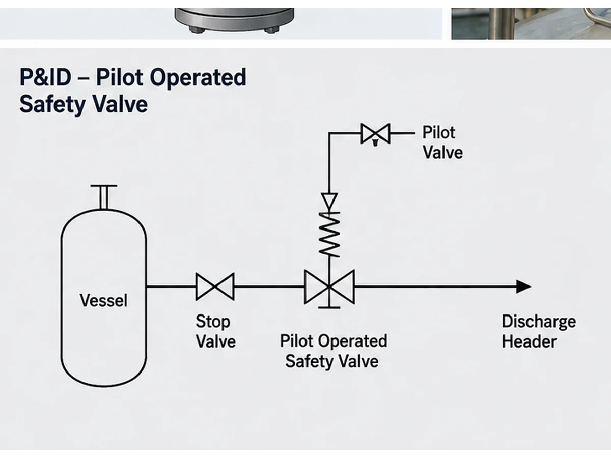
KI-generierte vereinfachte P&ID-Darstellung; kein Projektplan, Vorfallbericht oder Herstellerfreigabedokument.
Nachrüst- und Austauschsituationen
Die Fernmessung wird bei Austauscharbeiten oft übersehen. Ein Käufer kann Nenngröße, Flanschdruckstufe, Ansprechdruck und allgemeines Ventilaussehen abgleichen, aber versäumt, die alte Messanordnung, Pilotrohrleitungen, Filter, Drosseln, Abläufe, Absperrventile oder Begleitheizung zu prüfen.
Ein Austausch allein nach Aussehen oder Nenngrößenschild ist unsicher. Das vorhandene Datenblatt, Typenschild, P&ID, Fotos der installierten Rohrleitungen und alle Feldänderungsaufzeichnungen sollten vor der Auswahl eines Ersatz-pilotgesteuerten Sicherheitsventils überprüft werden.
| Bedingung | Fernmessung kann helfen, wenn | Fernmessung löst nicht | Zu bestätigende Daten |
|---|---|---|---|
| Langer oder einschränkender Zulauf | Der lokale Ventileinlassdruck entspricht möglicherweise nicht dem Druck des geschützten Geräts | Übermäßiger Einlassverlust, schlechte Rohrleitungsabstützung oder zu kleiner Entlastungspfad | Entlastungsströmungspfad, Einlassdruckverlust, R&I-Fließschema und Herstellergrenzen |
| Ferner Behälter- oder Kopfleitungsdruckpunkt | Der maßgebliche Druckpunkt befindet sich physisch entfernt vom Hauptventileinlass | Falsche Messpunktauswahl oder ungeprüftes Kopfleitungsdruckverhalten | Geschütztes Gerät, Entlastungsszenario und Druckquellenort |
| Nachrüstung oder Austausch | Die bestehende Installation verwendet bereits eine zugelassene Fernmessanordnung | Kopieren des Rohrleitungsbildes ohne Prüfung der Pilotkonstruktion und des Betriebsrisikos | Typenschild, Datenblatt, R&I-Fließschema, Fotos, Betriebshistorie und MOC-Aufzeichnungen |
Prüfung der Messleitungsauslegung vor der Angebotsanfrage
Vor der Angebotserstellung sollte die Messleitung als Teil der Ventilanforderung beschrieben werden. Die Angebotsanfrage sollte nicht nur “pilotgesteuertes Sicherheitsventil mit Fernmessung” sagen. Sie sollte definieren, welcher Druck gemessen wird, woher das Signal kommt und welche betrieblichen Risiken die Leitung beeinträchtigen können.
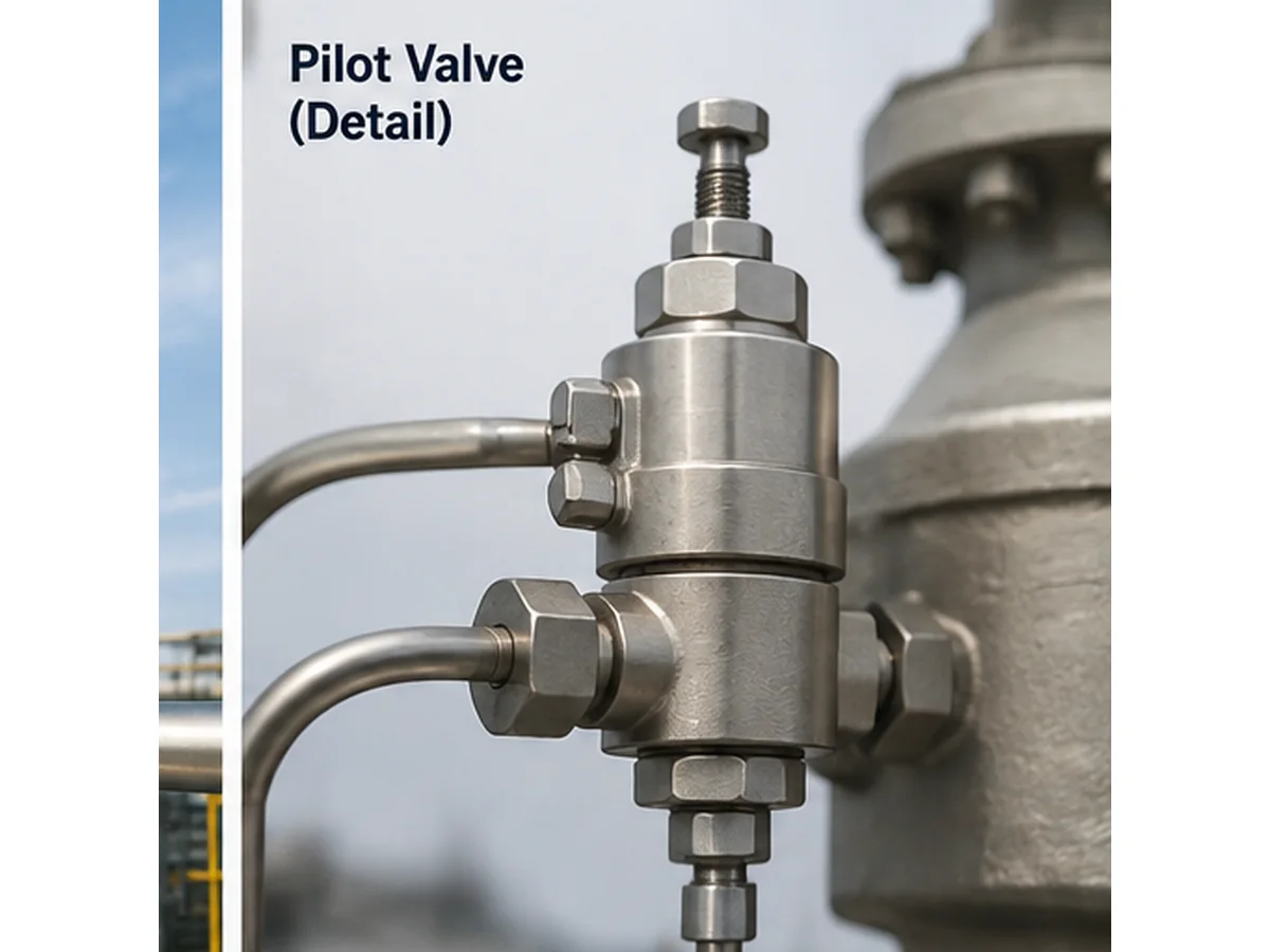
KI-generierte technische Nahaufnahme; Dateiname-zu-Bild-Formulierung wurde im HTML-Alt-, Titel- und Bildunterschriftentext kontrolliert.
Messpunkt und Entnahmestelle
Die Angebotsanfrage sollte den vorgeschlagenen Messpunkt identifizieren. Dies kann eine geschützte Ausrüstungsdüse, eine vorgeschaltete Behälterverbindung, eine Prozesskopfleitung, ein Ventileinlassanschluss oder ein vom Hersteller genehmigter Fernverbindungspunkt sein. Die Entnahmestelle sollte keine tote Leitung, Flüssigkeitsfalle oder Kontaminationsfalle erzeugen. Sie sollte auch einen Druckpunkt vermeiden, der unter dem maßgebenden Entlastungsfall nicht repräsentativ ist.
Rohrleitungsführung, Gefälle und mechanischer Schutz
Die Messleitungsführung sollte wo praktikabel kurz und direkt sein, aber die tatsächliche Route muss auch Zugänglichkeit, Vibration, thermische Bewegung, Entwässerung und Schutz vor mechanischer Beschädigung berücksichtigen. Die Leitung sollte nicht so verlegt werden, dass sie während der routinemäßigen Wartung betreten, gebogen, überhitzt, eingefroren oder getrennt werden kann.
Gefälle und Entwässerung sind besonders wichtig bei kondensierendem Dampf, Nassgas und Mehrphasenbetrieb. Eine Leitung, die auf einer Zeichnung akzeptabel aussieht, kann im Feld einen Tiefpunkt erzeugen. Dieser Tiefpunkt kann Flüssigkeit sammeln und die Druckübertragung zum Piloten verzögern.
Absperrung, Entwässerung und Wartungszugang
Absperrventile, Entwässerungen, Filter und Prüfanschlüsse können in einigen Systemen erforderlich sein, aber sie schaffen auch Ausfallrisiken, wenn sie falsch ausgewählt, geschlossen gelassen, verstopft oder modifiziert werden. Ob diese Elemente zulässig sind, hängt vom anwendbaren Code, der Projektspezifikation, den Verriegelungssteuerungen, den Betriebsverfahren und den Herstelleranweisungen ab.
Mediumspezifische Risiken
Die Fühlerleitung sollte anhand des tatsächlichen Mediums und der Phase überprüft werden: sauberes trockenes Gas, feuchtes Gas, Dampf oder kondensierender Dampf, Flüssigkeit, Zweiphasen-Entlastung, verschmutzte oder ablagerungsbildende Medien, korrosive Medien, polymerisierende oder kristallisierende Medien und gefrierende Außenanwendungen. Die Werkstoffgüte allein beweist keine Eignung. Die Fühlerleitung, Armaturen, Pilot-Innenteile, Dichtungen, Filter und benetzte Komponenten müssen mit dem Medium, der Temperatur und dem Wartungsplan kompatibel sein. Die Werkstoffeignung sollte auch Elastomer-Sitze oder O-Ringe, Dichtungswerkstoffe, Kleinrohrleitungen und Armaturen, benetzte Innenteile des Piloten und gegebenenfalls die Feder- oder Federkammerumgebung berücksichtigen.
| Betriebsbedingung | Bedenken zur Fernfühlerleitung | Vor RFQ prüfen | Keine Annahmen treffen |
|---|---|---|---|
| Sauberes trockenes Gas | Signalintegrität, Leckage und Vibration | Leitungsführung, Armaturen, Abstützung und Pilotanschluss | Dass jede Kleinrohrverlegung akzeptabel ist |
| Dampf oder kondensierender Dampf | Kondensatfalle, Wärmeverlust, verzögertes Signal | Gefälle, Entwässerung, Begleitheizung, Isolierung und Anfahrbedingung | Dass eine Trockengas-Fühleranordnung wiederverwendet werden kann |
| Verschmutzende, wachsartige oder polymerisierende Medien | Verengung, Verstopfung und Pilotkontamination | Filterstrategie, Spülzugang, Materialverträglichkeit und Wartungsintervall | Diese Fernmessung wird den verschmutzten Betrieb ohne Wartungskontrolle lösen |
| Korrosiver Dienst | Degradation der benetzten Teile von Rohr, Fitting, Dichtung und Pilotventil | Benetztes Material, Dichtungsmaterial, Federumgebung und Korrosionszuschlag | Allein das Gehäusematerial beweist die vollständige Eignung für den Betrieb |
| Gefrieren im Freien | Eisblockade und falsche Druckrückmeldung | Umgebungstemperatur, Wasserquelle, Begleitheizung, Isolierung und Entwässerung | Allein die Isolierung verhindert alle Ausfälle der Fühlleitung |
Häufige Risiken bei externer Druckentnahme
Die externe Druckentnahme kann die Druckdarstellung bei richtiger Anordnung verbessern, fügt jedoch eine Abhängigkeit von der Steuerleitung hinzu. Viele Ausfälle der externen Druckentnahme sind am Hauptventilkörper nicht offensichtlich. Sie können sich als Pilotinstabilität, falsches Öffnungsverhalten oder unerklärliche Leckage äußern.
| Risiko von Ausfällen | Mögliche Auswirkung | Vor-Ort-Prüfung | Benötigte Daten für Angebotsanfrage |
|---|---|---|---|
| Blockierte Fühlleitung | Verzögerte oder ausbleibende Pilotreaktion | Leitung, Armaturen, Filter und Verunreinigungen prüfen | Medium, Feststoffe, Korrosions- und Verschmutzungsrisiko |
| Undichte Armatur oder Leitung | Falsches Niederdrucksignal oder Instabilität | Armaturen und Leitungen auf Dichtheit prüfen | Rohrmaterial, Druck, Verlegung und Vibration |
| Kondensatsack | Gedämpfte oder verzögerte Reaktion | Gefälle, Tiefpunkte und Entwässerung prüfen | Mediumphase, Temperatur und Leitungsführung |
| Einfrieren | Verblockte Signalleitung | Prüfung auf Freiliegendes, Begleitheizung und Isolierung | Umgebungstemperatur und Kondensatrisiko |
| Falscher Isolierzustand | Schutzfunktion deaktiviert oder verfälscht | Ventilstellung bestätigen und Aufsperrsteuerung prüfen | Isolierphilosophie und -verfahren |
| Falsche Entnahmestelle | Pilot erfasst nicht repräsentativen Druck | P&ID mit Feldaufstellung vergleichen | Geschütztes Equipment und Entlastungsszenario |
Verstopfung und Verschmutzung
Eine verstopfte Messleitung kann verhindern, dass der Pilot das korrekte Drucksignal erhält. Die Verstopfung kann durch Schmutz, Korrosionsprodukte, Feststoffe im Prozess, Wachs, Polymer, Eis, Kondensat oder Montagerückstände verursacht werden. Ein häufiger Feldausfall tritt auf, wenn das Hauptventilgehäuse korrekt installiert ist, aber die kleine Messverbindung mit der Zeit eingeschränkt wird.
Leckage und falsche Druckrückmeldung
Eine undichte Verschraubung, ein gerissener Schlauch, eine lose Klemmverbindung oder eine beschädigte Kleinleitung kann das Drucksignal reduzieren oder verfälschen. Je nach Pilotdesign und Betriebsbedingung kann Leckage zu Instabilität, verzögertem Öffnen, falschem Wiedereinsetzen oder wiederholten Wartungsbeschwerden führen.
Kondensat, Einfrieren und Flüssigkeitsansammlungen
Kondensat ist eines der wichtigsten Risiken bei Dampf- oder Nassgasbetrieb. Eine Messleitung, die einen Tiefpunkt erzeugt, kann Flüssigkeit sammeln. Diese Flüssigkeit kann das Drucksignal verzögern, die Pilotreaktion dämpfen, bei kaltem Wetter einfrieren oder Korrosion verursachen.
Falscher Absperr- oder Bypass-Zustand
Ein Absperrventil, das geschlossen, teilweise geschlossen oder falsch verriegelt ist, kann die Messfunktion deaktivieren oder verfälschen. Eine Prüfanschluss- oder Bypass-Anordnung kann ein ähnliches Risiko darstellen, wenn sie nicht durch Betriebsanweisungen kontrolliert wird. Fernmessung sollte daher im R&I-Fließschema, in der Betriebsanleitung und in der Wartungscheckliste dokumentiert sein.
| Beobachtetes Symptom | Mögliche Ursache der Messleitung | Vor dem Ventilaustausch prüfen |
|---|---|---|
| Ventil scheint spät zu öffnen | Blockierte Leitung, Kondensatfalle, falscher Messpunkt oder verzögerte Druckübertragung | Druckentnahmestelle, Leitungsreinheit, Gefälle und Betriebsbedingung prüfen |
| Wiederholte Pilotinstabilität | Undichte Verschraubung, Vibration, ungestützte Leitung oder instabile Druckquelle | Rohrleitungsstützen, Armaturen, Druckquelle und Änderungen vor Ort prüfen |
| Unerwartetes Wiedereinsetzverhalten | Flüssigkeitstasche, Verunreinigung, falsche Entwässerungsbedingung oder Einschränkung der Pilotleitung | Entwässerungen, Tiefpunkte, Filterzustand und Wartungsprotokoll des Piloten prüfen |
| Anderes Verhalten nach Austausch | Alte Messanordnung unvollständig übernommen oder neues Pilotdesign nicht an die Rohrleitungsführung angepasst | Alte und neue Datenblätter, Pilotmodell, Rohrleitungsführung und Herstelleranweisungen vergleichen |
| Kein eindeutiger Schaden am Hauptventil, aber das Ansprechverhalten bleibt falsch | Messleitung oder Absperreinrichtung können den Piloten fehlleiten | R&I-Fließschema, Verriegelungsstellung, Prüfanschluss, Bypass und Fotos vor Ort prüfen |
Fernmessung ersetzt keine Kapazitäts- und Systemprüfung
Die Fernmessung ändert, wo der Pilot sein Drucksignal erhält. Sie beweist nicht, dass das ausgewählte Ventil genügend Abblaskapazität hat, dass die Installation akzeptabel ist oder dass das Austrittssystem den Abblasstrom bewältigen kann.
Technische Grenze: Einstelldruck ist nicht Kapazität, und die Nennweite ist nicht die zertifizierte Abblaskapazität. Ein Ventil mit gleicher Ein- und Austrittsgröße kann je nach Bauart, Öffnungsquerschnitt, Ausflussbeiwert, Fluidbasis und anwendbarer Norm eine unterschiedliche zertifizierte oder dokumentierte Kapazität haben.
Die Kapazität hängt weiterhin von der erforderlichen Abblaslast ab
Ein pilotgesteuertes Sicherheitsventil kann korrekt eingestellt sein, aber dennoch ungeeignet sein, wenn die erforderliche Abblasleistung, die Fluidbasis, die Abblasetemperatur, der Gegendruck oder die gewählte Öffnung falsch sind. Verwenden Sie den Sicherheitsventil-Auslegung und zertifizierter Abblaseleistung Leitfaden, wenn das Projekt eine klarere Kapazitätsbasis benötigt.
Prüfungen des Ein- und Auslasssystems gelten weiterhin
Eine Fernmessung kann dem Piloten helfen, einen repräsentativeren Druckpunkt zu erfassen, aber die Einlassleitung beeinflusst weiterhin den Durchfluss in das Ventil. Übermäßiger Einlassdruckverlust kann zu Instabilität und Kapazitätsproblemen beitragen. Der Auslassgegendruck bleibt ebenfalls wichtig. Fremdgegendruck und Aufstaugegendruck müssen getrennt geprüft werden. Für eine umfassendere Erläuterung von Fremdgegendruck, Aufstaugegendruck und den Auswahlgrenzen für faltenbalgkompensierte Ventile lesen Sie den Gegendruck und Faltenbalg Leitfaden.
Herstellerdaten und Projektspezifikationen bleiben maßgeblich
Die endgültige Auswahl hängt von der gewählten Ventilkonstruktion, den Herstellerdaten, der geltenden Normausgabe, der Projektspezifikation und den örtlichen behördlichen Anforderungen ab. Die Anfrage sollte angeben, ob das Projekt ASME, API, ISO, EN, GB oder einen anderen Rahmen verwendet, und die übernommene Ausgabe sollte für das Projekt verifiziert werden. Für eine breitere Normenübersetzung lesen Sie API 520 Auslegung von Sicherheitsventilen und API 521 Druckentlastungssysteme.
Was Fernmessung bewirken kann
- Bessere Druckdarstellung, wenn der zugelassene Messpunkt vom Hauptventileinlass abweicht.
- Klarere Pilotenreferenz in einigen Anordnungen mit Druckverlustbedenken.
- Verbesserte Fehlersuche, wenn der Messpfad dokumentiert und zugänglich ist.
Was Fernmessung nicht ersetzen kann
- Berechnung der Entlastungsmenge und der erforderlichen Kapazität.
- Zertifizierte oder dokumentierte Kapazitätsprüfung.
- Prüfung von Einlassdruckverlust, Auslassgegendruck und Abblasesystem.
- Herstellerfreigabe für die ausgewählte Pilotkonfiguration.
Zusammengesetzte technische Szenarien für die Fernabfrageprüfung
Die folgenden Szenarien sind zusammengesetzte technische Beispiele für Schulungszwecke. Sie sind keine Kundendatensätze, Unfallberichte oder Nachweise für eine bestimmte ZOBAI-Produktleistung.
Szenario 1: Irreführender lokaler Einlassdruck
Ein Druckbehälter entlädt über eine Rohrleitung zu einem pilotgesteuerten Sicherheitsventil, wobei der Einlassdruckverlust während des Abblasevorgangs signifikant werden kann. Die Fernabfrage kann dem Piloten helfen, ein repräsentativeres Drucksignal zu erhalten, aber das Ventil und die Einlassleitung müssen dennoch als System betrachtet werden. Die vorbeugende Maßnahme besteht darin, den Druckpunkt des geschützten Geräts zu definieren, den Abblasefall zu berechnen und die Sensoranordnung mit dem Ventilhersteller abzustimmen.
Szenario 2: Kondensat in der Sensorleitung
Eine Sensorleitung für feuchten Dampf wird mit einem Tiefpunkt verlegt. Dort sammelt sich Kondensat und dämpft das Pilotsignal. Das Feldproblem kann wie eine Piloteninstabilität aussehen, aber die Überprüfung sollte Streckenführung, Gefälle, Entwässerung, Begleitheizung, Anfahrbedingungen und Mediumphase umfassen. Die Korrekturmaßnahme besteht nicht einfach darin, den Piloten zu ersetzen; die Sensorleitung muss korrigiert oder kontrolliert werden.
Szenario 3: Austausch ohne Leitungsprüfung
Ein Käufer für einen Austausch gleicht Flanschgröße und Ansprechdruck ab, liefert aber kein P&ID oder Fotos der Sensorleitung. Das Risiko besteht nicht nur in einer dimensionalen Abweichung; die Pilotenanforderung und der Sensorweg können unterschiedlich sein. Die vorbeugende Maßnahme besteht darin, Typenschild, Datenblatt, vorhandene Pilotrohrleitung, Abblaseszenario und alle Feldänderungen zu überprüfen, bevor das Ersatzventil ausgewählt wird.
RFQ- und Wartungscheckliste
Eine gute RFQ für ein ferngesteuertes pilotgesteuertes Sicherheitsventil sollte den Betrieb und die Anordnung der Fernsteuerung beschreiben. Der Käufer sollte sich nicht auf eine kurze Beschreibung wie “gleich wie altes Ventil” oder “Pilotventil mit Fernsteuerung” verlassen.”
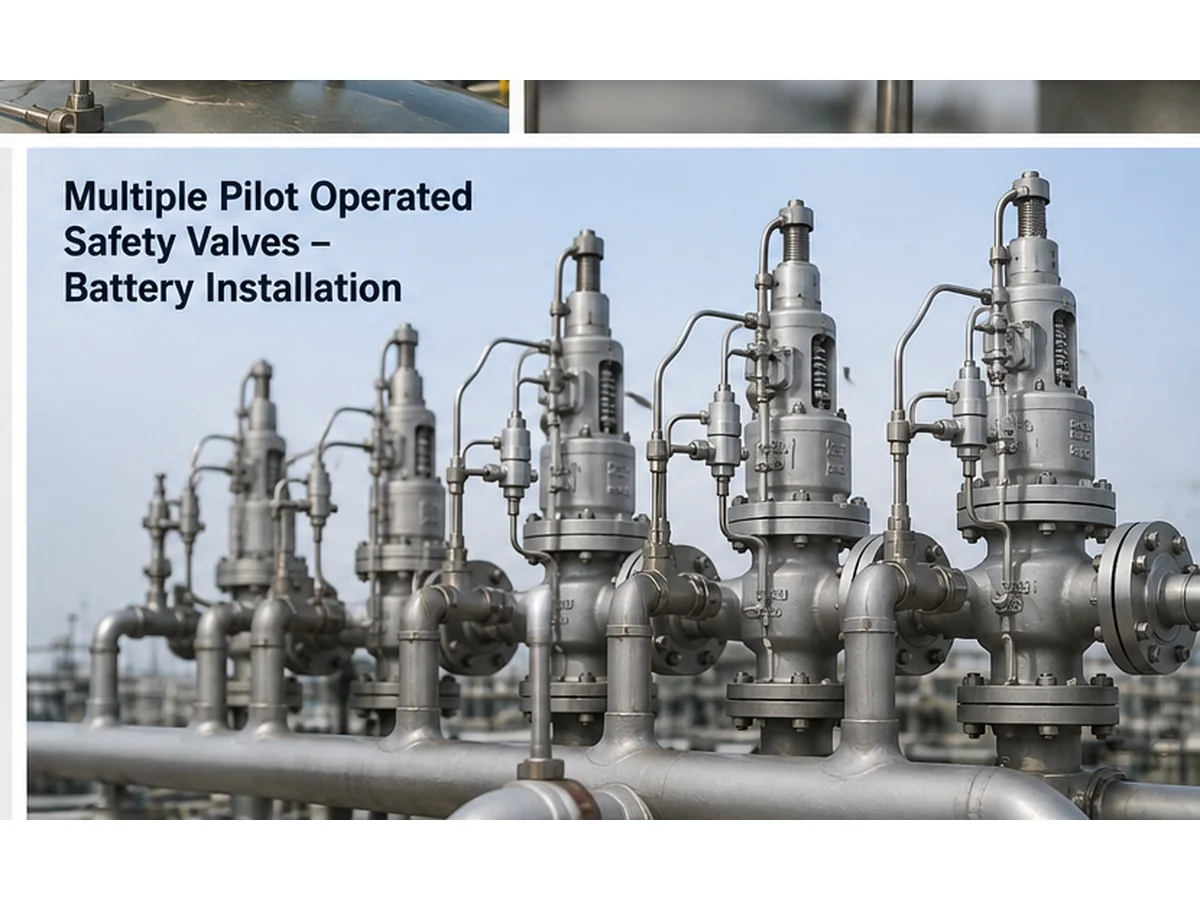
KI-generierte Installationskontext-Visualisierung; sie beweist kein reales Projekt, keine zertifizierte Kapazität, kein Testergebnis und keine Kundeninstallation.
| Datenkategorie | Erforderliche Informationen | Warum es wichtig ist |
|---|---|---|
| Geschütztes Equipment | Behälter, Kessel, Leitung, Kompressor, Skid oder anderes System | Definiert die zu schützende Druckquelle |
| Entlastungsszenario | Blockierter Auslass, Feuer, Rohrbruch, Reglerausfall oder anderer Fall | Definiert die maßgebliche Last und den Druckzustand |
| Medium und Phase | Gas, Dampf, Flüssigkeit, Zweiphasenstrom, verschmutzt, korrosiv oder kondensierend | Beeinflusst die Zuverlässigkeit der Sensorleitung und die Ventilkonstruktion |
| Druckdaten | Betriebsdruck, MAWP/Konstruktionsdruck und Ansprechdruck | Verhindert Verwirrung bei der Druckterminologie |
| Kapazität | Erforderliche Entlastungskapazität und Kapazitätsbasis | Verhindert die Auswahl basierend auf der Anschlussgröße |
| Temperatur | Betriebs- und Entlastungstemperatur | Beeinflusst Material, Dichtungen und Kondensat-/Gefrierrisiko |
| Gegendruck | Überlagerter und aufgebauter Gegendruck | Beeinflusst Ventilauswahl und Stabilität |
| Fühlerleitung | Punkt, Strecke, Gefälle, Länge, Isolierung, Entwässerung und Begleitheizung | Steuert die Zuverlässigkeit des Pilotsignals |
| Dokumente | Datenblatt, R&I-Fließschema, Typenschild, Fotos und Normenanforderungen | Ermöglicht Austausch und technische Prüfung |
Tipp zur Austauschprüfung: Senden Sie für ein vorhandenes POSV Nahaufnahmen des Pilotventils, der Rohrleitungen, des Messabgriffs, der Absperrventile, der Entwässerungen, der Filter, des Typenschilds und der umgebenden Ein-/Auslassleitungen. Ein Ventil, das in Größe und Ansprechdruck übereinstimmt, kann dennoch falsch sein, wenn der Pilotkreis oder der Fernmessweg nicht kompatibel ist.
Fernmessdetails vor der POSV-Auswahl senden
Senden Sie Ihre geschützte Ausrüstung, das Entlastungsszenario, Medium und Phase, Betriebsdruck, MAWP oder Auslegungsdruck, Ansprechdruck, erforderliche Entlastungskapazität, Entlastungstemperatur, Gegendruck, Ein-/Auslassanschluss, Fernmesspunkt, Messleitungsweg, Materialien und geltende Normen.
- Für neue Projekte: Entlastungsszenario, Prozessdaten und vorgeschlagenen Messpunkt angeben.
- Für Austauschprojekte: Typenschild des alten Ventils, Datenblatt, Installationsfotos und R&I-Fließschema beifügen.
- Für Fehlerbehebung: Symptome, Betriebshistorie, Wartungsmaßnahmen und alle Feldänderungsaufzeichnungen angeben.
Normen und technische Referenzhinweise
Die Auswahl von pilotgesteuerten Sicherheitsventilen mit Fernabtastung sollte anhand des übernommenen Projektcodes, der Herstelleranweisungen und der geltenden Normenausgabe überprüft werden. Die folgenden offiziellen Quellen dienen nur als Referenz und bedeuten nicht, dass jedes ZOBAI-Produkt automatisch jede Zertifizierung oder jedes Codezeichen trägt.
- ISO 4126-4:2013 — offizielle ISO-Seite für pilotgesteuerte Sicherheitsventile.
- API 520 Teil I — offizielle API-Seite für Auslegungs- und Auswahlkontext.
- API Standard 521 — offizielle API-Seite für Druckentlastungs- und Entlastungssysteme.
- ASME BPVC Section XIII, 2025 — offizielle ASME-Seite für Regeln zum Überdruckschutz.
FAQ
Was ist Fernabfrage bei einem pilotgesteuerten Sicherheitsventil?
Bei der Fernmessung erhält der Pilot den Druck von einem ausgewählten entfernten Punkt, anstatt nur den Druck am oder in der Nähe des Haupteinlasses zu erfassen. Ziel ist es, den Pilot auf einen Druckpunkt reagieren zu lassen, der die geschützte Anlage besser repräsentiert.
Ist Fernerkundung immer besser als lokale Erkundung?
Nein. Fernmessung kann in manchen Anordnungen nützlich sein, birgt jedoch Risiken der Messleitung wie Verstopfung, Leckage, Kondensat, Einfrieren, falsche Absperrung und Ansprechverzögerung. Sie muss für den jeweiligen Einsatzfall und die Ventilkonstruktion geprüft werden.
Kann Fernerkundung den Druckverlust am Einlass lösen?
Eine Fernmessung kann dem Piloten helfen, ein repräsentativeres Drucksignal zu erhalten, ersetzt jedoch nicht die Überprüfung des Einlassdruckverlusts. Einlassleitung, Kapazität, Stabilität und Herstellergrenzen müssen weiterhin geprüft werden.
Was passiert, wenn die Fühlleitung blockiert ist?
Eine blockierte Fühlerleitung kann verhindern, dass der Pilot den tatsächlichen Druck des geschützten Geräts erhält. Dies kann zu verzögertem Öffnen, falschem Ansprechen, Instabilität oder einem Ausfall der erwarteten Funktion führen.
Soll die Messleitung ein Absperrventil haben?
Das hängt vom anwendbaren Regelwerk, der Projektspezifikation, der Betriebsanweisung, der Offenhalte-Steuerung und der Herstelleranweisung ab. Ein Absperrventil kann die Wartung unterstützen, aber wenn es falsch gesteuert wird, kann es die Schutzfunktion außer Kraft setzen oder verfälschen.
Kann ich ein POSV durch passende Größe und Ansprechdruck ersetzen?
Nein, Anschlussgröße und Ansprechdruck reichen nicht aus. Die Austauschprüfung sollte die zertifizierte oder dokumentierte Kapazität, die Pilotkonfiguration, die Leitungsführung der Fühlerleitung, das Medium, die Temperatur, den Gegendruck, die Installation und die geltenden Dokumente umfassen.
Welche Daten sollte ich vor der Angebotsanfrage übermitteln?
Senden Sie die zu schützende Ausrüstung, das Entlastungsszenario, Medium und Phase, Betriebsdruck, MAWP/Auslegungsdruck, Ansprechdruck, erforderliche Entlastungskapazität, Entlastungstemperatur, Gegendruck, Einlass-/Auslassanschlüsse, Messpunkt und Messleitungsverlegung.
Was sollte die Wartung prüfen, bevor sie das Pilotventil verantwortlich macht?
Vor der Schlussfolgerung, dass das Pilotventil selbst die Ursache ist, sollte die Wartung den Messanschluss, Leitungsverstopfungen, Leckagen, Tiefpunkte, Kondensat, Frostgefahr, die Stellung des Absperrventils, die Rohrleitungsabstützung, Filter, Entwässerungen und etwaige Änderungen vor Ort prüfen.






Kommentare
Kesari Alloys
Die Betonung darauf, dass die Messleitung Teil der Schutzfunktion ist, ist entscheidend. Es ist leicht zu übersehen, wie eine verstopfte oder undichte Leitung die Fehlersuche in die Irre führen kann. Ich frage mich, ob Sie näher erläutern könnten, wie verschiedene Materialien und Installationstechniken für die Messleitung deren Zuverlässigkeit beeinflussen können, insbesondere unter Bedingungen mit möglicher Kondensation oder Verstopfungen.