Integrated Pressure Relief for Equipment Packages
Built-in Safety Valves Manufacturer
Built-in safety valves are pressure relief devices integrated directly into OEM equipment, tank top assemblies, process skids, compact pressure modules and machine-mounted pressure systems. Selection should not be based on body size or thread size alone. The equipment port, set pressure, required relieving capacity, discharge path, back pressure, material compatibility and access for recalibration all determine whether the valve can protect the system safely.
Standards: ASME / API / ISO / GB Options
Service: Steam / Gas / Vapor / Liquid
Applications: OEM Equipment / Skids / Tank Top Assemblies
Key Checks: Set Pressure / Capacity / Back Pressure / Blowdown
Materials: WCB / CF8 / CF8M / CF3M / Alloy Options
Docs: Datasheet / Test Report / Material Certificate / Calibration Record
Selection should be confirmed against the actual medium, set pressure, operating pressure, relieving capacity, back pressure, temperature, installation layout, equipment interface and applicable code requirements.
Safety Valve Categories
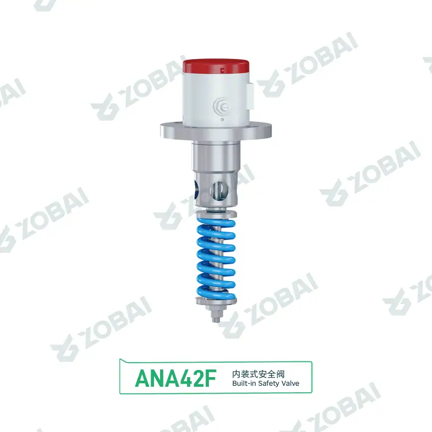
ANA42F DN50 Built-In Tank Safety Valve
Built-in Safety Valves for Integrated Equipment Pressure Protection
A built-in safety valve is a pressure relief valve installed as part of a machine, vessel, tank top assembly, compressor package, skid-mounted unit or OEM equipment module. Unlike a standalone flanged safety valve installed on open piping, a built-in valve is usually constrained by equipment geometry, available service space, discharge direction, vibration, heat transfer and replacement footprint.
What makes a built-in safety valve different
The relief function is the same: the valve must open at the specified set pressure and provide verified capacity for the governing relief case to prevent unsafe pressure rise. The difference is the installation boundary. In built-in service, the valve inlet may be a machined boss, threaded port, sanitary tank top connection, compact flange, manifold pocket or direct equipment connection.
This means the engineer must review not only the valve itself, but also the protected equipment interface, inlet passage, discharge route, access for testing, drainage, cleaning method and whether the valve can be removed without cutting pipe or dismantling the machine.
Engineering selection boundary
“Built-in” describes how the valve is installed, not a separate safety code category by itself. The valve may still be spring loaded, threaded, flanged, sanitary, full lift, low lift, open bonnet, closed bonnet or balanced, depending on the medium and project requirement.
A built-in safety valve still needs verified set pressure, required relieving capacity, manufacturer or code-certified capacity where required, material compatibility, a safe discharge route and practical recalibration access.
How a Built-in Safety Valve Relieves Pressure
In most built-in applications, the valve is directly connected to the pressure zone of the protected equipment. When the internal pressure reaches the set pressure, the disc lifts against spring force or another closing force. The medium then flows through the built-in inlet passage, valve seat and outlet path to atmosphere, a safe drain, a recovery line or a discharge header.
Pressure Sensing
The valve senses static pressure at the equipment port. The inlet passage must not restrict or delay pressure transmission.
Opening Point
At set pressure, the disc starts to lift. The actual opening behavior depends on valve type, medium, temperature and installation condition.
Relieving Flow
The valve discharges through the integrated outlet. Capacity must be checked against the credible overpressure case, not only against connection size.
Reseating
After pressure drops, the valve closes. Dirt, vibration, back pressure or seat damage may prevent tight reseating.
Built-in Valve Design Points That Affect Safety
A built-in safety valve should be reviewed as part of the protected equipment. A valve that works correctly on a test bench may still perform poorly if the equipment port is too restrictive, the outlet is blocked by surrounding structure, or the valve cannot be maintained after installation.
Equipment Port and Inlet Passage
The equipment port and internal passage must transmit pressure and relieving flow without excessive restriction. A small drilled passage, sharp elbow, long internal channel or partially blocked boss can increase inlet pressure loss and create unstable operation during relief.
For replacement projects, the port thread, sealing face, insertion depth, gasket arrangement and interference with nearby components should be checked before assuming that a similar-looking valve is interchangeable.
Relieving Capacity and Discharge Direction
Built-in valves are often compact, but the required relieving capacity still comes from the protected equipment scenario. Thermal expansion, blocked outlet, regulator failure, fire case, compressor discharge blockage or overfilling may require different flow rates.
The outlet should discharge to a safe location. If the built-in outlet is connected to a tube, silencer, drain, recovery line or common header, built-up back pressure and outlet resistance must be reviewed.
Low-profile Body, Bonnet and Spring Chamber
Built-in safety valves are frequently selected where height, weight or surrounding clearance is limited. A low-profile design can help equipment packaging, but it may also reduce space for spring design, heat dissipation, wrench access or lifting device arrangement.
High temperature, corrosive atmosphere, washdown service or machine vibration may require a closed bonnet, suitable spring material, corrosion-resistant trim or locking method for adjustment components.
Maintenance, Removal and Recalibration Access
A built-in safety valve should be removable for inspection, cleaning, seat repair and recalibration. If the valve is trapped behind guards, insulation, electrical cabinets or process piping, the maintenance interval becomes harder to control.
For OEM equipment, the drawing should define the valve position, access envelope, torque limits, seal type, nameplate visibility and whether the valve can be bench-tested after removal.
Built-in Safety Valve Fit Check
Use this screening tool to identify whether a built-in safety valve may be suitable for your equipment layout. This tool does not replace sizing, code review or project engineering approval.
Initial result: likely suitable for engineering review
Built-in installation may be practical if the complete inlet path is adequate, the discharge route is safe, the valve is accessible for recalibration and the governing relief case and required capacity are known. Final selection still depends on medium, pressure, temperature, back pressure, valve type and project requirements.
Parameters That Must Be Confirmed Before Selecting a Built-in Safety Valve
Built-in Safety Valve vs Standalone Safety Valve
The decision is not only about available space. A built-in valve reduces installation envelope but increases the importance of equipment interface control, access planning and replacement compatibility.
| Item | Built-in Safety Valve | Standalone Safety Valve |
|---|---|---|
| Installation position | Integrated into equipment, tank top, machine body, manifold, compact skid or OEM module. | Installed on separate piping, vessel nozzle or branch connection. |
| Main engineering advantage | Compact layout, fewer external components and controlled OEM package design. | Easier piping flexibility, larger valve options and simpler field replacement. |
| Main engineering risk | Restricted inlet passage, limited discharge clearance, poor access or difficult replacement. | Incorrect piping layout, excessive inlet pressure loss or discharge reaction load. |
| Capacity review | Must include equipment port and internal passage, not only valve catalog capacity. | Must include inlet and outlet piping losses, fittings and discharge system. |
| Maintenance | Requires access planning during equipment design. | Usually easier to isolate, remove and recalibrate if piping space is available. |
| Typical use | OEM packages, compact vessels, sanitary tank tops, compressor skids, process modules and small pressure systems. | Pressure vessels, boilers, piping systems, process units and utility headers. |
Where Built-in Safety Valves Are Commonly Used
OEM equipment and compact pressure modules
Built-in safety valves are often used on packaged equipment where the pressure relief device must fit within a machine envelope. The valve should be selected together with the equipment port, access panel and discharge route.
Compressor, pump and utility skids
For skids, vibration, pulsation, outlet tubing and maintenance clearance are critical. A built-in valve should not discharge toward operators, electrical panels, hot surfaces or walkways.
Tank top and sanitary process assemblies
In hygienic or clean process service, the valve must be compatible with cleaning method, drainage, seal material, surface finish expectation and tank pressure relief scenario.
Small pressure vessels and process packages
Built-in installation can reduce external piping, but the valve still needs a defined set pressure, relieving capacity, material specification, inspection access and documentation package.
Built-in Safety Valve Selection Table
| Application Condition | Possible Built-in Valve Arrangement | Key Engineering Check | Main Risk | Data Needed Before RFQ |
|---|---|---|---|---|
| Clean compressed air or inert gas equipment | Threaded or compact spring loaded built-in valve | Set pressure, required air capacity, discharge direction and vibration | Chatter, leakage or unsafe discharge toward personnel | Medium, set pressure, flow case, thread, outlet direction |
| Steam or hot vapor module | Metal seated built-in safety valve with suitable bonnet design | Temperature, spring exposure, discharge reaction and insulation clearance | Spring relaxation, burns, leakage or poor reseating | Steam condition, temperature, capacity, installation drawing |
| Sanitary tank or clean liquid vessel | Tank top or sanitary connection pressure relief valve | Cleanability, drainage, seal compatibility and overfilling case | Contamination, trapped liquid or insufficient relief path | Medium, CIP/SIP condition, connection type, tank design pressure |
| Corrosive chemical package | Stainless steel or alloy built-in valve with compatible trim | Body, disc, guide, spring, seal and fastener material compatibility | Corrosion, sticking, seat leakage or spring failure | Chemical name, concentration, temperature, material restriction |
| Outlet connected to recovery line or common header | Built-in valve with back pressure review or balanced design if suitable | Superimposed and built-up back pressure, outlet resistance and header interaction | Reduced capacity, unstable lift or failure to reseat | Outlet pressure, header layout, pipe length, simultaneous relief scenario |
| Replacement of existing OEM valve | Dimensionally compatible built-in safety valve | Nameplate data, port geometry, seat size, lift, capacity and certification basis | Wrong replacement due to same thread but different internal capacity | Old valve photos, nameplate, drawing, set pressure and medium |
This table is for engineering screening only. Final selection depends on medium, pressure, temperature, back pressure, valve type, required relieving capacity, applicable standards and project documentation requirements.
Built-in Safety Valve Mistakes That Cause Field Problems
Assuming the equipment port is large enough
A compact valve may have enough certified capacity on paper, but the actual built-in inlet passage can be smaller than expected. The valve may chatter or fail to reach stable lift if the port creates excessive inlet pressure loss.
Replacing by thread size only
Two valves with the same thread can have different seat diameters, lift, spring range and capacity. For OEM replacement, the old nameplate, drawing, set pressure and relieving capacity should be checked before selecting a new valve.
Hiding the valve inside the machine
If the valve cannot be removed, cleaned or recalibrated after final assembly, the equipment may pass initial testing but become difficult to maintain safely during service life.
Built-in Safety Valve Troubleshooting Table
| Symptom | Possible Cause | Engineering Check | Corrective Action |
|---|---|---|---|
| Valve chatters during relief | Restricted inlet passage, excessive outlet back pressure or oversized valve | Review equipment port, inlet loss, outlet tubing and required flow case | Modify port design, reduce outlet resistance or select a suitable valve type |
| Valve leaks after equipment testing | Seat contamination, vibration, poor alignment or damaged sealing surface | Inspect seat, medium cleanliness, mounting stress and operating pressure margin | Clean, repair, recalibrate, improve filtration or review operating pressure |
| Valve cannot be removed | Access envelope not considered in equipment design | Check surrounding guards, insulation, pipe routing and wrench clearance | Revise equipment layout or add a removable access panel for maintenance |
| Valve opens below expected pressure | Wrong spring range, damaged spring, temperature effect or incorrect calibration | Compare nameplate data, test report and service temperature | Recalibrate or replace with correct set pressure and material design |
| Capacity appears insufficient | Wrong sizing basis, smaller internal orifice or restricted discharge path | Review required relieving capacity, certified capacity and discharge layout | Recalculate sizing and select correct model, orifice and outlet arrangement |
| Corrosion or sticking found during inspection | Material mismatch, trapped liquid, aggressive atmosphere or poor drainage | Check wetted parts, spring chamber exposure, seal material and cleaning process | Upgrade materials, improve drainage or change valve configuration |
Standards and Documents to Confirm
Standards commonly reviewed
Built-in safety valve projects may refer to pressure relief standards according to the protected equipment, market, medium and code requirement. The applicable document should be defined by the project specification, not assumed from the word “built-in.”
- ASME BPVC Section VIII for pressure vessel applications where applicable.
- ASME BPVC Section I for boiler-related applications where applicable.
- API 520 Part I and installation guidance for process systems.
- API 521 for overpressure scenarios and relief system design review.
- API 527 where the selected valve design and project specification use API 527; otherwise confirm the applicable leakage criterion.
- ISO 4126-1 for safety valves and ISO 4126-related documents where applicable.
- API Standard 2000 or ISO 28300 when the protected equipment is an atmospheric or low-pressure storage tank and the project scope requires tank inbreathing or outbreathing review.
- ISO 15156-1 / NACE MR0175 where the project falls within its H₂S-containing oil and gas production scope; confirm downstream, refining or other chemical-service requirements separately.
Documents buyers often request
Documentation should match the safety function and project risk. For built-in valves, the interface drawing is often as important as the valve datasheet because it controls how the valve sees pressure and discharges flow.
- Valve datasheet with model, size, set pressure and material.
- Certified capacity or sizing basis when required by the project.
- Equipment interface drawing or installation envelope.
- Set pressure calibration record.
- Seat tightness test report when leakage control is specified.
- Material certificate for body, trim or wetted parts when required.
- Nameplate, tag number and inspection documentation.
- Operation and maintenance instruction for removal and recalibration.
Related Pages for Built-in Safety Valve Selection
Built-in safety valve selection should connect the equipment interface, valve type, installation condition, material compatibility and documentation package. Use these related pages to continue the engineering review.
Core valve types
Equipment and application pages
Official Standards References for Integrated Pressure Relief Review
The applicable standard depends on the protected equipment, medium, jurisdiction and project specification. Use official standards sources when confirming code scope, sizing basis, tank venting scope, material requirements and acceptance documents.
Pressure relief device standards
- API 520 Part I: Sizing and Selection of Pressure-Relieving Devices
- API 521: Pressure-Relieving and Depressurizing Systems
- ISO 4126-1: Safety Valves
- ASME BPVC Section XIII — overpressure-protection rules for pressure relief devices, testing, marking, capacity certification and installation.
Special service references
- API Standard 2000 — confirm the current active tank-venting edition in the official API Digital Catalog.
- ISO 28300: Venting of Atmospheric and Low-Pressure Storage Tanks
- ISO 15156-1:2020 / NACE MR0175 — cracking-resistant metallic materials for H₂S-containing oil and gas production environments.
- National Board NB-18 — searchable pressure-relief-device certification, manufacturer and certified-device information.
Built-in Safety Valve FAQs
These answers clarify the installation boundary, quotation data, chatter risk and standards commonly reviewed for integrated pressure protection.
Need an Engineering Review for a Built-in Safety Valve?
Send the operating conditions and equipment interface information before quotation. For replacement projects, include the existing valve nameplate, installation photos and port dimensions. This helps avoid a valve that fits mechanically but does not match the required set pressure, capacity or service condition.
Prepare these data before RFQ
TECHNICAL INSIGHTS
Insights for Safer Valve Selection
FAQ
Built-in Safety Valve FAQ
What is a built-in safety valve?
A built-in safety valve is a pressure relief valve installed directly into a machine, vessel, tank top assembly, skid, manifold or OEM equipment package. It opens at a specified set pressure to discharge excess pressure from the protected equipment. The term “built-in” describes the installation arrangement, not a separate valve code category.
Is a built-in safety valve different from a standard safety valve?
The pressure relief function is similar, but the installation boundary is different. A standard safety valve is often installed on separate piping or a vessel nozzle. A built-in safety valve is integrated into equipment, so the equipment port, internal passage, discharge path, access space and replacement footprint must be reviewed together with the valve.
Can a built-in safety valve be selected only by thread size?
No. Thread size only confirms mechanical connection. It does not confirm set pressure, spring range, orifice area, certified capacity, material compatibility, seat tightness or discharge behavior. For replacement projects, the existing valve nameplate, drawing and operating conditions should be checked before selecting a new valve.
What data is required to quote a built-in safety valve?
Key RFQ data include medium, set pressure, operating pressure, temperature, required relieving capacity, back pressure, inlet port size, thread or connection standard, outlet direction, material requirement, applicable code and equipment drawing. For replacement, photos of the old valve and nameplate are very helpful.
What causes a built-in safety valve to chatter?
Common causes include restricted inlet passage, excessive inlet pressure loss, high built-up back pressure, an oversized valve, unstable flow, vibration or a discharge path with too much resistance. The valve, equipment port and outlet routing should be reviewed as one system.
Can built-in safety valves be used for corrosive media?
Connection sizeYes, but material compatibility must be reviewed carefully. Body material alone is not enough. The nozzle, disc, guide, spring, seals, fasteners and spring chamber exposure should be checked against the chemical composition, concentration, temperature and cleaning conditions. only tells you how the valve connects to the piping. It does not prove that the valve can discharge enough flow. Certified relieving capacity confirms whether the valve can protect the equipment during the required overpressure scenario.
How often should a built-in safety valve be inspected or recalibrated?
The interval depends on medium, pressure, temperature, service severity, local regulations, project requirements and site maintenance policy. Built-in installation should allow the valve to be removed, inspected, cleaned, repaired and recalibrated without excessive equipment dismantling.
Which standards apply to built-in safety valves?
Applicable standards depend on the protected equipment, market and service condition. Common references may include ASME BPVC Section VIII, ASME BPVC Section I, API 520, API 521, API 527, ISO 4126 and project-specific pressure equipment rules. Tank venting applications may require different documents such as API 2000 or ISO 28300.

Raymon Yu
“When a safety valve fails to pop on site, it’s rarely because someone can’t read a standard. It’s usually because critical operating parameters (like backpressure or relief temperature) were assumed instead of specified. I reviewed the key technical content on this page to keep it practical, API/ASME spec-aligned, and RFQ-ready. (We prefer assumptions for lunch choices.)”
What I work on daily: reviewing drawings and project specs, supporting engineer-to-engineer questions, resolving capacity calculations, material selection, and backpressure impacts so production and quoting stay consistent. (Yes—set pressure and seat tightness test records get plenty of attention.)