Scopri quando un liquido in blocco crea un caso di sfioro per dilatazione termica, cosa determina la capacità e la pressione di taratura e quali dati verificare prima della selezione della valvola.

Una linea di liquido isolata può diventare un problema di sovrapressione quando il liquido è intrappolato all'interno di un confine di pressione definito e la sua temperatura può aumentare senza spazio sufficiente o un altro percorso adeguato per accomodare l'espansione. La prima domanda ingegneristica quindi non è “Quale valvola di sicurezza per dilatazione termica dovrei acquistare?” È “Questa sezione crea effettivamente uno scenario di sfioro per dilatazione termica credibile?”
Una valvola chiusa di per sé non stabilisce lo scenario di sfioro completo. La dimensione del tubo non determina la capacità di scarico richiesta. Il servizio normale con liquido non prova che il fluido rimanga monofase attraverso il dispositivo di sfioro. Anche una valvola correttamente dimensionata deve comunque essere riesaminata con la sua linea di scarico e la contropressione prevista.
Definire il confine intrappolato → confermare lo scenario di dilatazione termica → stabilire il carico di sfioro richiesto → impostare la base di pressione → verificare lo stato del fluido in scarico → riesaminare il sistema di uscita → valutare la valvola candidata e le evidenze per la RFQ.
La guida HSE del Regno Unito sulle tubazioni di processo riconosce che il liquido può essere intrappolato tra valvole chiuse e che le variazioni di temperatura possono quindi causare dilatazione termica e perdita di contenimento. Inquadra inoltre lo sfioro di pressione in base alle effettive condizioni di esercizio e isolamento piuttosto che alla sola presenza di una valvola. Guida HSE sulle tubazioni.
Per un contesto più ampio sulla sovrapressione delle pipeline, vedere la guida applicativa ZOBAI per lo sfioro nelle pipeline. Quella pagina copre diversi scenari di sovrapressione nelle pipeline; questo articolo resta focalizzato sulla dilatazione termica del liquido intrappolato.
Quando una linea di liquido isolata diventa un caso di sovrapressione per dilatazione termica?
Un caso di dilatazione termica inizia con un effettivo confine in pressione con liquido intrappolato,
non semplicemente con bassa portata o una singola valvola chiusa.
-
Definire il confine di isolamento.
Individuare le valvole, le interfacce delle apparecchiature o gli altri punti di isolamento che possono trattenere il liquido. -
Determinare cosa è intrappolato.
Stabilire se la sezione può diventare piena di liquido o comunque sufficientemente confinata
perché la dilatazione termica sia rilevante. -
Individuare un aumento di temperatura credibile.
Considerare le condizioni di esercizio, di arresto, di standby o ambientali pertinenti che possono riscaldare
il liquido intrappolato. -
Confrontare lo scenario con il confine in pressione protetto.
Determinare se la condizione risultante può mettere in crisi la base di pressione applicabile per
le tubazioni o l'apparecchiatura.
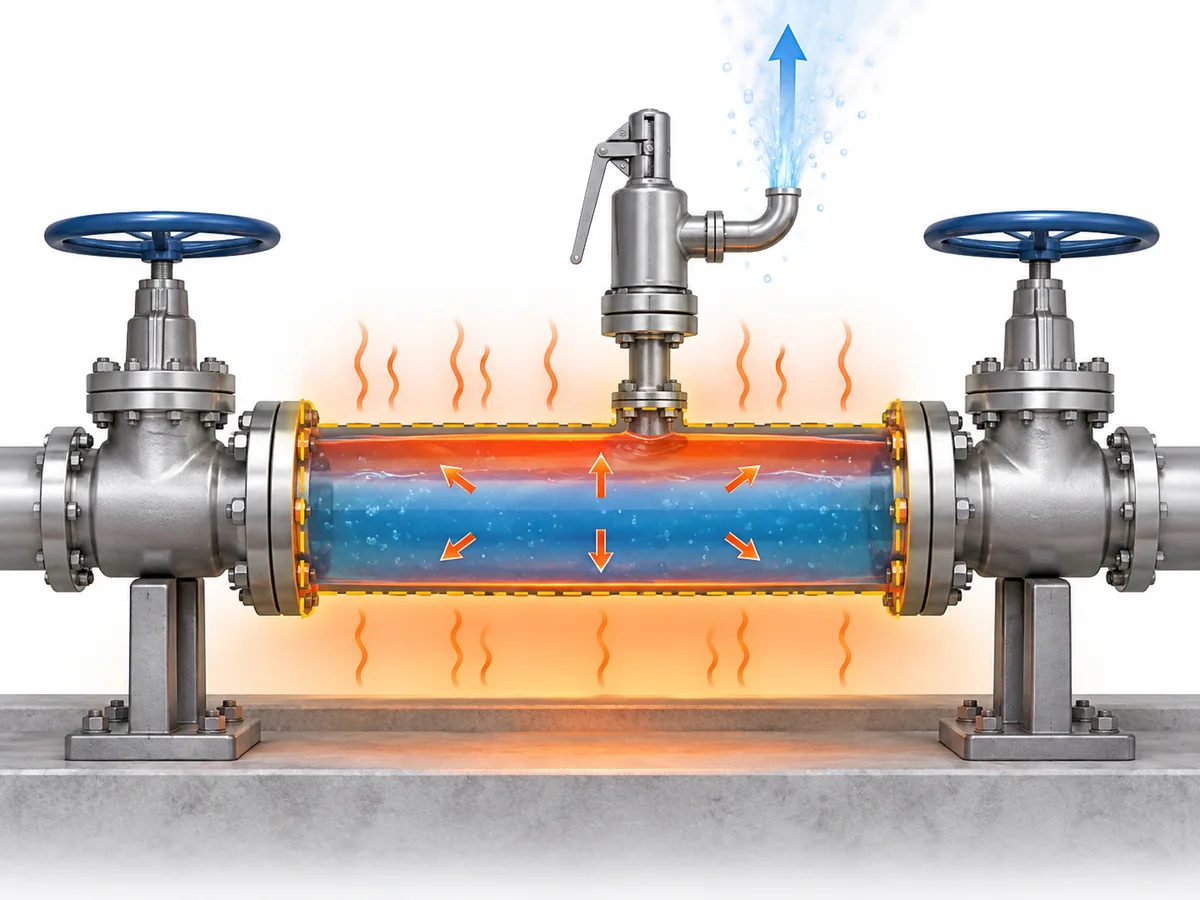
I liquidi sono molto meno comprimibili dei gas. Quando un volume isolato è sostanzialmente
riempito di liquido, il volume aggiuntivo di liquido prodotto dal riscaldamento può quindi tradursi in
un brusco aumento di pressione, a meno che il sistema non disponga di un modo adeguato per assorbirlo o scaricarlo.
L'apporto termico dipende dall'installazione. A seconda del sistema, le fonti rilevanti possono includere
il riscaldamento ambiente o solare, il riscaldamento elettrico, un'area circostante riscaldata o apparecchiature
di processo adiacenti. La presenza di una di queste fonti non la rende automaticamente il caso
determinante; la condizione credibile deve essere stabilita per l'installazione effettiva.
Bloccato non significa semplicemente “assenza di flusso”.”
Significa che il sistema può creare un confine di pressione del liquido vincolato in condizioni
in cui l'espansione termica può mettere alla prova tale confine.
Questa è la condizione da stabilire prima di dimensionare o selezionare un dispositivo di sfioro.
Ogni sezione di liquido isolata necessita di una valvola di sfioro termico dedicata?
Non automaticamente.
L'identificazione di uno scenario credibile di espansione termica stabilisce che il rischio di sovrapressione
richiede una risposta ingegneristica adeguata. Non dimostra, di per sé, che
una specifica configurazione con valvola di sfioro termico dedicata sia l'unica soluzione accettabile.
| Domanda tecnica | Che cosa è stato effettivamente stabilito? |
|---|---|
| Il liquido può rimanere intrappolato e riscaldarsi? | Esiste un potenziale scenario di espansione termica. |
| Tale condizione può mettere in crisi il limite di pressione protetto? | La protezione contro la sovrapressione deve essere valutata. |
| La soluzione deve necessariamente essere una valvola di sfioro termico dedicata? | Dipende dalla strategia di protezione accettata e dalla base di progetto. |
| Una valvola specifica è adatta? | Ciò richiede un servizio definito e una documentazione specifica del prodotto. |
Depending on the system and applicable engineering basis, protection can involve a
pressure-relief device or another engineered arrangement that prevents unacceptable
pressure from developing. A solution accepted for one service or jurisdiction should
not be generalized to every process line.
API Standard 521 is a system-level pressure-relief and depressuring reference for petroleum,
petrochemical, LNG and related facilities. Its scope supports evaluating the relief scenario
and system before treating a product name as the design decision.
API Standard 521 information.
The terminology can also mislead procurement. Valvola di sfioro idrostatica
is used in some industries for devices protecting piping where liquid can be trapped
between shut-off valves. That practical terminology overlap does not make
“hydrostatic relief valve” and “thermal relief valve” universally interchangeable across
every fluid, code or industry.
Scenario confirmed → protection strategy defined → applicable project/code basis checked
→ device selected and verified.
For broader standards context, see
ZOBAI’s API 521 pressure-relief systems guide
.
What Determines the Required Thermal Relief Rate and Valve Capacity?
A thermal expansion relief valve should be selected from the
required relieving duty, not from pipe diameter or a habitual
“small thermal valve” size.
For a liquid-filled thermal-expansion case, the relief requirement depends on the thermal
condition and on fluid properties that determine how the liquid responds as temperature
changes. Once the required relieving flow is established, actual valve sizing also depends
on the applicable relieving pressure, temperature, outlet/back-pressure condition and
fluid state.
Credible thermal condition → applicable fluid properties → required relieving rate
→ relieving pressure and outlet conditions → applicable sizing method
→ required flow area/capacity → candidate valve capacity verification.
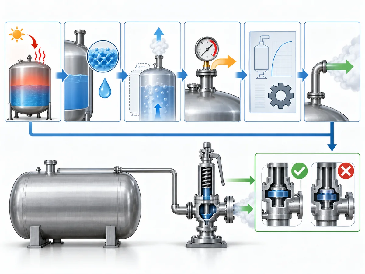
Two shortcuts are worth rejecting. La dimensione della connessione non è capacità:
a valve may fit the line mechanically while still lacking the capacity required for the
relief case. And “thermal relief flow is often relatively small” is not a sizing
metodo: even a modest duty has to be established before a candidate valve can
be accepted.
API 520 Part I is specifically concerned with pressure-relieving-device sizing and
selection within its scope.
API 520 Part I information.
For the detailed general sizing workflow rather than repeating it here, see
ZOBAI’s safety valve sizing and certified relieving capacity guide
.
The practical inputs for this thermal-expansion case include:
- the protected section and relevant trapped volume;
- the credible thermal condition or heat input;
- fluid identity and the physical properties required by the applicable calculation;
- pressione e temperatura di scarico;
- the required relieving rate;
- expected back pressure; and
- the fluid-state assumption used by the sizing method.
Only after the required duty has been established should the selected valve’s documented
capacity be compared against it.
Thermal relief is duty-sized, not simply small-sized.
How Should the Set-Pressure Basis Be Established?
Set pressure should be derived from the pressure boundary being protected,
not copied from normal operating pressure or selected from a generic percentage rule.
That separation is consistent with recognized relief-device specification practice:
operating pressure, set pressure, relieving/design temperatures, allowable overpressure,
back pressure and required capacity are treated as distinct inputs rather than
interchangeable values.
Baker Hughes pressure-relief valve specification guidance
.
| Termine di pressione | Role in the thermal-relief decision |
|---|---|
| Pressione operativa | The pressure the system normally experiences. |
| Protected design / allowable pressure basis | The applicable pressure boundary for the piping or equipment being protected. |
| Pressione di taratura | The specified pressure associated with the relief device beginning its defined opening action. |
| Pressione di sfioro | The pressure condition used for relief sizing or capacity assessment. |
| Contropressione | Pressure acting on or downstream of the valve outlet. |
Those values are related, but they are not interchangeable. Identify which piping and
components lie inside the blocked-in boundary, then establish the governing pressure basis
under the applicable design code, equipment rules and project specification before
assigning the valve set pressure.
Scope discipline matters here. A pressure rule written for a vessel should not automatically
be transplanted into generic process piping, and a regulation written specifically for LPG,
ammonia or another service should not be generalized to unrelated fluids or jurisdictions.
This article therefore does not create a universal rule such as
“set the thermal relief valve at a fixed percentage above operating pressure.”
Where a numerical relationship is prescribed, it belongs to the applicable equipment,
code, project and jurisdictional basis.
For an RFQ, set pressure should be treated as the result of a protected-system engineering
decision, not merely as a field to complete on a vendor datasheet.
Why the Relieving Fluid State Must Be Checked, Not Assumed
A line can be liquid-filled before the relief event without remaining a simple
single-phase liquid system throughout the complete relieving path.
Relief-valve engineering guidance distinguishes straightforward liquid sizing from cases
in which subcooled liquid can flash as pressure falls through the valve. That makes the
relieving-state check a real sizing boundary rather than a semantic detail.
LESER engineering guidance.
As pressure changes through the valve and downstream piping, the relationship between fluid
pressure and temperature can change. Under some conditions, the liquid remains adequately
subcooled and a liquid-sizing basis remains appropriate. Under others, flashing or a more
complex phase condition may need to be considered.
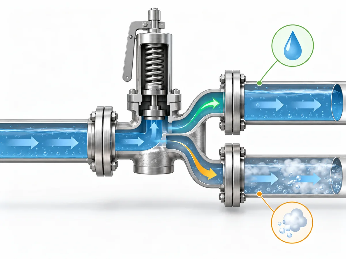
At the relevant relieving pressure and temperature—and as pressure falls through the
valve and outlet system—does the fluid remain in the phase assumed by the sizing method?
If the assumed phase remains valid, the case can continue under the appropriate liquid-sizing
methodology. If meaningful phase change occurs, the required inputs and sizing treatment can
change. That does not mean every thermal-expansion case is two-phase; it means the phase
assumption should be verified rather than inherited from the normal operating description.
A procurement description such as “liquid service, thermal relief”
therefore does not by itself prove the relieving-state assumption required for final sizing.
This article treats initial phase e relieving phase
as related but separate engineering inputs.
Why Discharge Routing and Back Pressure Are Part of the Relief Decision
A correctly selected valve is not enough if the installed relief path cannot perform
under the defined scenario.
Protected section → valve inlet → relief device → outlet piping → disposal or recovery destination.
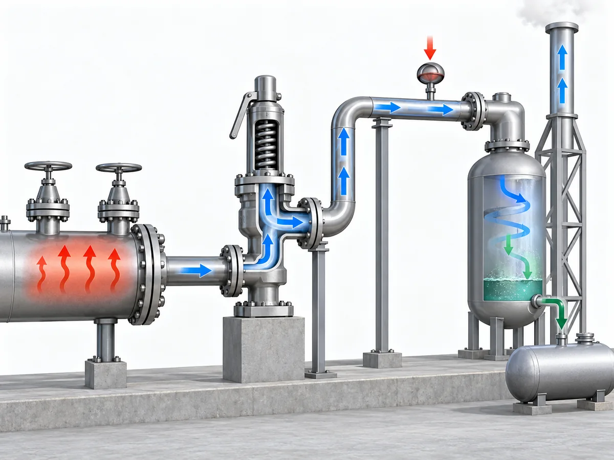
The review should establish where the relieved liquid will go, whether that route remains
available during the relief case, and what pressure the downstream system will impose on
the valve.
Back pressure can influence relief-valve behavior and available capacity, depending on the
valve design and system. Emerson’s pressure-relief-valve engineering handbook treats back
pressure as a factor that can affect opening or reseating behavior, stability and capacity,
so it belongs in candidate verification rather than being left as a post-purchase piping detail.
Emerson Pressure Relief Valve Engineering Handbook
.
For a deeper treatment of that interface, see
ZOBAI’s back-pressure and bellows engineering guide
.
The destination itself is service-dependent. A small expected thermal-relief rate does
not prove that unrestricted atmospheric discharge is acceptable. Conversely, a closed
return, drain or recovery system is not automatically suitable if it imposes unacceptable
back pressure or can be isolated when relief is required.
ISO 23251 provides an international pressure-relief-system framework for petroleum,
petrochemical and natural-gas industries. Its current 2019 edition explicitly supplements
API 521 6th Edition, so project teams should confirm the adopted standard set rather than
silently treating different editions as textually equivalent.
ISO 23251 information.
Where can the relieved fluid go without compromising either safe disposal or the valve’s
ability to perform its relief function?
Detailed flare design, closed-header hydraulics and valve-architecture thresholds belong
to separate engineering work. This article only needs to establish that the outlet system
forms part of the relief decision.
What Information Belongs in a Thermal-Relief RFQ or Engineering Review?
A technically useful RFQ should describe the protected system and relief duty,
not simply request a valve by nominal size.
Separate the process inputs from the supplier verification:
| Buyer / engineer should define or assign | Supplier / candidate should confirm |
|---|---|
| Protected piping or equipment boundary | Exact valve configuration offered |
| Fluid and relevant composition | Wetted-material, seat and seal suitability |
| Normal fluid state | Pressure-temperature suitability |
| Pressione e temperatura operative | Available set-pressure capability |
| Governing protected-pressure basis | Documented capacity for the specified duty |
| Credible thermal condition or heat source | Selected flow area or valve size |
| Required relieving rate, or responsibility for determining it | Effect of specified back pressure on the candidate |
| Relieving-phase assumption | Connection and pressure-class suitability |
| Contropressione attesa | Applicable inspection or test documentation |
| Relief destination | Requested conformity documentation, where applicable |
| Applicable project code or specification | Deviations, limitations and unresolved points |
Required relieving capacity is not the same as connection size.
One is a process-protection requirement; the other is primarily an installation characteristic.
Required capacity is also not the same as compliance evidence.
Capacity documentation addresses the flow-performance question under the applicable basis.
Material certificates, inspection records or other project-required conformity evidence
answer different procurement questions.
A supplier should not have to guess the relief scenario. If the protected pressure basis,
thermal condition, required relieving rate, fluid state or expected back pressure remains
undefined, those gaps should be resolved before a proposed valve is treated as an approved
candidate.
Can the proposed valve be traced back to a defined thermal-expansion duty, protected
pressure boundary, relieving state and outlet condition—and does the supplier evidence
address each of those requirements?
If not, the candidate is not ready for approval merely because a catalogue uses the words
sfioro termico o hydrostatic relief.