了解封闭液体在何种情况下形成热膨胀泄放工况、排量与整定压力由哪些因素决定,以及在选阀前需要核实哪些数据。.

封闭液体管线中,当液体被困在确定的压力边界内,且温度升高时没有足够空间或其他适当途径容纳膨胀,就可能形成超压问题。因此,首要的工程问题并不是 “我应该购买哪种热膨胀泄压阀?” 而是 “该管段是否确实构成可信的热膨胀泄放工况?”
阀门关闭本身并不能确立完整的泄放工况。管道尺寸不能决定所需泄放量。常规液体工况并不能证明流体在整个泄放装置中始终保持单相。即使安全阀选型正确,仍须结合其排放管路和预期背压进行复核。.
确定封闭边界 → 确认热膨胀工况 → 确定所需泄放负荷 → 确定压力基准 → 核实泄放流体状态 → 复核出口系统 → 评估安全阀选型方案与询价资料。.
英国 HSE 工艺管道指南指出,液体可能被封闭在关闭的阀门之间,温度变化随后会引起热膨胀并导致完整性丧失。该指南还强调,压力泄放应基于实际运行和隔离工况,而非仅凭是否安装了阀门来判断。. HSE 管道指南.
如需了解更广泛的管道超压背景,请参阅 ZOBAI 的管道泄放应用指南. 该页面涵盖多种管道超压工况;本文则聚焦于封闭液体管路的热膨胀问题。.
封闭液体管路何时构成热膨胀超压工况?
热膨胀工况的起点是 真实存在的封闭液体压力边界,,
而不仅仅是低流量或单个阀门关闭。.
-
确定隔离边界。.
识别可能存留液体的阀门、设备接口或其他隔离点。. -
确定被封闭的介质。.
判断该管段是否可能达到满液状态,或以其他方式受到足够约束,
从而使热膨胀成为需要考虑的因素。. -
确定可信的温度升高。.
考虑可能使封闭液体升温的相关运行、停车、备用或环境条件。
封闭液体。. -
将该工况与被保护的压力边界进行对比。.
判断由此产生的工况是否会超出适用的压力基准,该基准针对
管道或设备。.
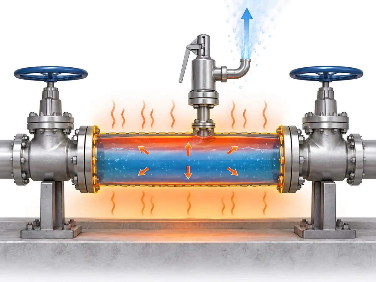
液体的可压缩性远低于气体。当隔离容积内基本充满
液体时,升温产生的额外液体体积可能因此转化为
急剧的压力升高,除非系统具备足够的方式来容纳或泄放该压力。.
热量输入因装置而异。根据系统的不同,相关来源可能包括
环境或日照升温、伴热、周围受热区域或相邻工艺
设备。存在其中某一来源并不自动使其成为控制
工况;必须针对实际装置确定可信工况。.
封闭并不只是指“无流动”。”
它是指系统在热膨胀可能对该边界构成挑战的条件下
能够形成受约束的液体压力边界。.
这是在确定泄放装置尺寸或选型之前需要确立的条件。.
是否每个被隔离的液体管段都需要专用热膨胀泄压阀?
并非自动如此。.
识别出可信的热膨胀工况,即可确认超压风险
需要采取适当的工程应对措施。这并不能仅凭该工况就证明
某一特定的专用热膨胀泄压阀配置是唯一可接受的方案。.
| 工程问题 | 实际已确立的是什么? |
|---|---|
| 液体是否可能被封闭并升温? | 存在潜在的热膨胀工况。. |
| 该工况是否会威胁受保护的承压边界? | 必须评估超压保护措施。. |
| 解决方案是否必须采用专用热膨胀泄压阀? | 这取决于所采用的保护策略和项目依据。. |
| 特定阀门是否适用? | 这需要明确的工况条件以及针对该产品的具体依据。. |
根据系统及适用的工程依据,保护措施可采用
泄压装置或其他工程配置,以防止产生不可接受的
压力。适用于某一工况或某一司法管辖区的方案,不应
推广至所有工艺管线。.
API 521 标准是石油、,
石化、LNG 及相关设施的系统级压力泄放与降压参考依据。其范围支持在将某一产品名称作为设计决策之前,
对泄放工况和系统进行评估。.
API 521 标准信息.
术语也可能对采购产生误导。. 静水泄放阀
在某些行业中用于保护可能因截断阀之间积液而超压的管道
装置。这种实际术语重叠并不意味着
“静水压泄压阀”与“热膨胀泄压阀”在所有
适用于各种流体、规范或行业。.
工况确认 → 保护策略确定 → 核查适用项目/规范依据
→ 选定并验证泄放装置。.
如需了解更全面的标准背景,请参阅
ZOBAI 的 API 521 压力泄放系统指南
.
热膨胀泄放量与安全阀排量由哪些因素决定?
热膨胀泄压阀应根据
所需泄放负荷, 选型,而不是根据管道直径或习惯性的
“小型热膨胀阀”规格。.
对于充满液体的热膨胀工况,泄放要求取决于热
条件以及决定液体随温度变化响应的流体物性
确定所需泄放流量后,实际阀门定径还取决于
适用的泄放压力、温度、出口/背压工况及
流体状态。.
可信热工况 → 适用流体物性 → 所需泄放速率
→ 泄放压力与出口工况 → 适用定径方法
→ 所需流通面积/排量 → 候选阀门排量校核。.
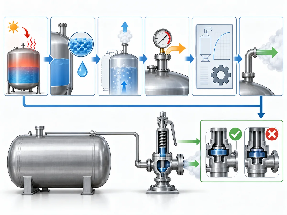
有两种简化做法应当避免。. 连接尺寸不等于排量:
阀门可能在机械上适配管线,但仍不具备该
泄放工况所需的排量。此外, “热泄放流量通常相对较小”并不是定径
方法: 即使是较小的工况,也必须在候选阀门
被接受之前予以确定。.
API 520 Part I 专门涉及其范围内的压力泄放装置定径和
选型。.
API 520 Part I 信息.
关于详细的一般定径工作流程,而非在此重复,请参见
ZOBAI 的安全阀定径与认证泄放能力指南
.
该热膨胀工况的实用输入包括:
- 受保护管段及相关封闭容积;;
- 可信的热条件或热输入;;
- 流体标识及适用计算所需的物理性质;;
- 泄放压力和温度;;
- 所需泄放量;;
- 预期背压;以及
- 定径方法所采用的流体状态假设。.
只有在确定所需泄放工况后,才应将所选安全阀的文档化
排量与所需泄放量进行对比。.
热泄放应按泄放工况确定规格,而非简单选用小规格。.
整定压力基准应如何确定?
整定压力应依据 被保护的压力边界,
确定,而非照搬正常工作压力或按通用百分比规则选取。.
这种区分符合公认的泄放装置选型规范:
工作压力、整定压力、泄放/设计温度、允许超压,,
背压与所需排量作为两个不同的输入参数处理,而非
可互换的数值。.
Baker Hughes 泄压阀技术规格指南
.
| 压力术语 | 在热泄放决策中的作用 |
|---|---|
| 工作压力 | 系统正常运行时所承受的压力。. |
| 被保护设计/允许压力基准 | 被保护管道或设备所适用的压力边界。. |
| 整定压力 | 泄放装置开始其规定开启动作时所对应的整定压力。. |
| 泄放压力 | 用于泄放定径或排量评估的压力工况。. |
| 背压 | 作用于阀门出口侧或出口下游的压力。. |
这些数值相互关联,但不可互换。确定哪些管道和
部件位于隔离边界之内,然后确定控制压力基准
under the applicable design code, equipment rules and project specification before
assigning the valve set pressure.
Scope discipline matters here. A pressure rule written for a vessel should not automatically
be transplanted into generic process piping, and a regulation written specifically for LPG,
ammonia or another service should not be generalized to unrelated fluids or jurisdictions.
This article therefore does not create a universal rule such as
“set the thermal relief valve at a fixed percentage above operating pressure.”
Where a numerical relationship is prescribed, it belongs to the applicable equipment,
code, project and jurisdictional basis.
For an RFQ, set pressure should be treated as the result of a protected-system engineering
decision, not merely as a field to complete on a vendor datasheet.
Why the Relieving Fluid State Must Be Checked, Not Assumed
A line can be liquid-filled before the relief event without remaining a simple
single-phase liquid system throughout the complete relieving path.
Relief-valve engineering guidance distinguishes straightforward liquid sizing from cases
in which subcooled liquid can flash as pressure falls through the valve. That makes the
relieving-state check a real sizing boundary rather than a semantic detail.
LESER engineering guidance.
As pressure changes through the valve and downstream piping, the relationship between fluid
pressure and temperature can change. Under some conditions, the liquid remains adequately
subcooled and a liquid-sizing basis remains appropriate. Under others, flashing or a more
complex phase condition may need to be considered.
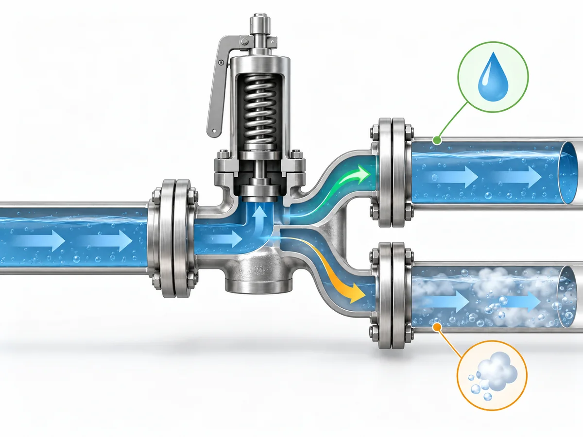
At the relevant relieving pressure and temperature—and as pressure falls through the
valve and outlet system—does the fluid remain in the phase assumed by the sizing method?
If the assumed phase remains valid, the case can continue under the appropriate liquid-sizing
methodology. If meaningful phase change occurs, the required inputs and sizing treatment can
change. That does not mean every thermal-expansion case is two-phase; it means the phase
assumption should be verified rather than inherited from the normal operating description.
A procurement description such as “liquid service, thermal relief”
therefore does not by itself prove the relieving-state assumption required for final sizing.
This article treats initial phase 和 relieving phase
as related but separate engineering inputs.
Why Discharge Routing and Back Pressure Are Part of the Relief Decision
A correctly selected valve is not enough if the installed relief path cannot perform
under the defined scenario.
Protected section → valve inlet → relief device → outlet piping → disposal or recovery destination.
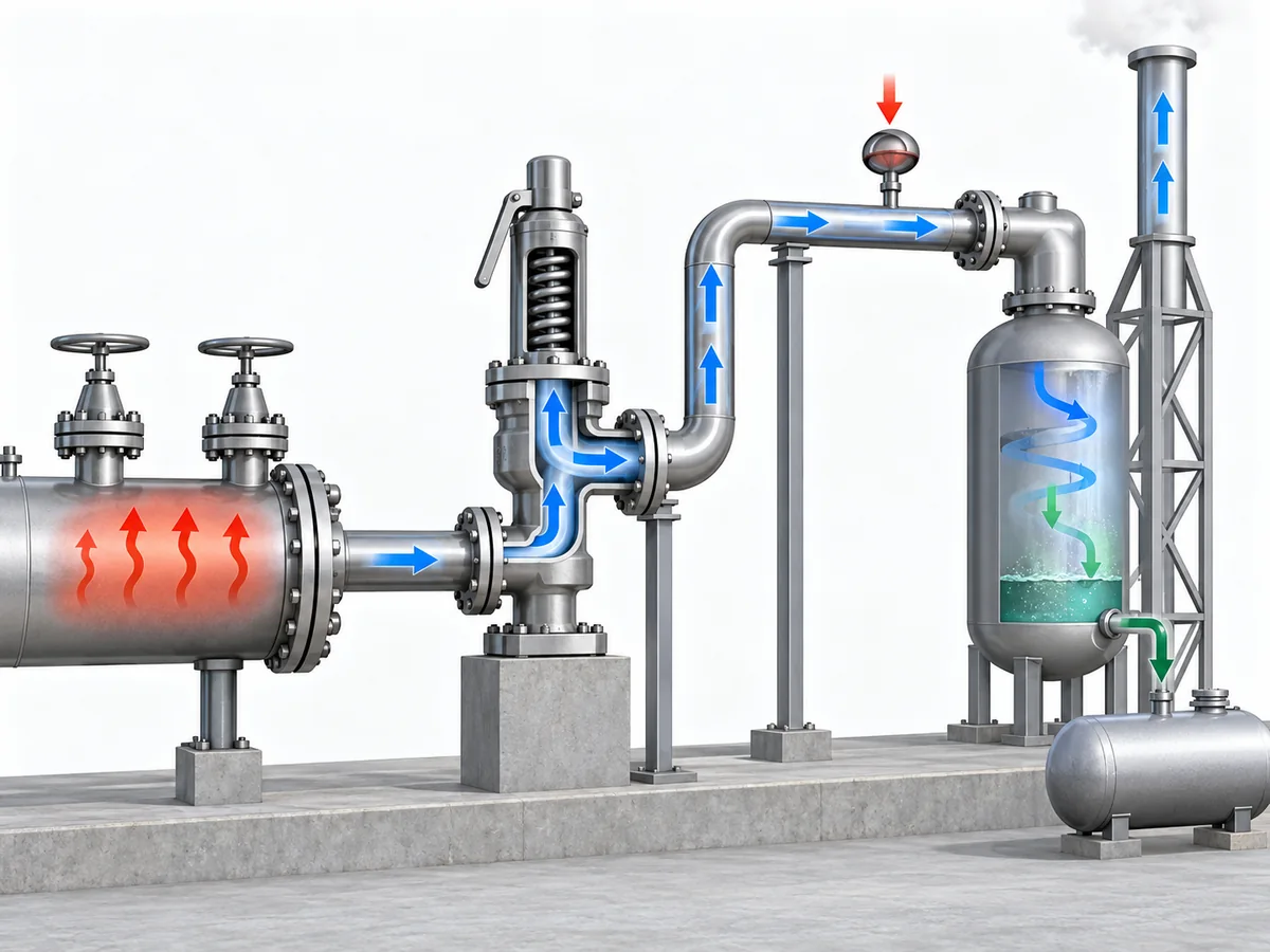
The review should establish where the relieved liquid will go, whether that route remains
available during the relief case, and what pressure the downstream system will impose on
the valve.
Back pressure can influence relief-valve behavior and available capacity, depending on the
valve design and system. Emerson’s pressure-relief-valve engineering handbook treats back
pressure as a factor that can affect opening or reseating behavior, stability and capacity,
so it belongs in candidate verification rather than being left as a post-purchase piping detail.
Emerson 泄压阀工程手册
.
For a deeper treatment of that interface, see
ZOBAI’s back-pressure and bellows engineering guide
.
The destination itself is service-dependent. A small expected thermal-relief rate does
not prove that unrestricted atmospheric discharge is acceptable. Conversely, a closed
return, drain or recovery system is not automatically suitable if it imposes unacceptable
back pressure or can be isolated when relief is required.
ISO 23251 provides an international pressure-relief-system framework for petroleum,
petrochemical and natural-gas industries. Its current 2019 edition explicitly supplements
API 521 6th Edition, so project teams should confirm the adopted standard set rather than
silently treating different editions as textually equivalent.
ISO 23251 information.
Where can the relieved fluid go without compromising either safe disposal or the valve’s
ability to perform its relief function?
Detailed flare design, closed-header hydraulics and valve-architecture thresholds belong
to separate engineering work. This article only needs to establish that the outlet system
forms part of the relief decision.
What Information Belongs in a Thermal-Relief RFQ or Engineering Review?
A technically useful RFQ should describe the protected system and relief duty,
not simply request a valve by nominal size.
Separate the process inputs from the supplier verification:
| Buyer / engineer should define or assign | Supplier / candidate should confirm |
|---|---|
| Protected piping or equipment boundary | Exact valve configuration offered |
| Fluid and relevant composition | Wetted-material, seat and seal suitability |
| Normal fluid state | Pressure-temperature suitability |
| Operating pressure and temperature | Available set-pressure capability |
| Governing protected-pressure basis | Documented capacity for the specified duty |
| Credible thermal condition or heat source | Selected flow area or valve size |
| Required relieving rate, or responsibility for determining it | Effect of specified back pressure on the candidate |
| Relieving-phase assumption | Connection and pressure-class suitability |
| Expected back pressure | Applicable inspection or test documentation |
| Relief destination | Requested conformity documentation, where applicable |
| Applicable project code or specification | Deviations, limitations and unresolved points |
Required relieving capacity is not the same as connection size.
One is a process-protection requirement; the other is primarily an installation characteristic.
Required capacity is also not the same as compliance evidence.
Capacity documentation addresses the flow-performance question under the applicable basis.
Material certificates, inspection records or other project-required conformity evidence
answer different procurement questions.
A supplier should not have to guess the relief scenario. If the protected pressure basis,
thermal condition, required relieving rate, fluid state or expected back pressure remains
undefined, those gaps should be resolved before a proposed valve is treated as an approved
candidate.
Can the proposed valve be traced back to a defined thermal-expansion duty, protected
pressure boundary, relieving state and outlet condition—and does the supplier evidence
address each of those requirements?
If not, the candidate is not ready for approval merely because a catalogue uses the words
热泄放 或 hydrostatic relief.