تعرّف على متى يؤدي السائل المحتجز عند الإغلاق إلى حالة تنفيس بسبب التمدد الحراري، وما الذي يحدد سعة التصريف وضغط الفتح، وأي البيانات يجب التحقق منها قبل اختيار الصمام.

قد يتحول خط سائل مغلق إلى مشكلة ضغط زائد عندما يُحتجز السائل داخل حدود ضغط محددة وترتفع درجة حرارته دون مساحة كافية أو مسار مناسب آخر لاستيعاب التمدد. لذلك فإن السؤال الهندسي الأول ليس “أي صمام تنفيس للتمدد الحراري يجب أن أشتري؟” بل هو “هل يُنشئ هذا القسم فعلاً حالة تنفيس موثوقة للتمدد الحراري؟”
الصمام المغلق بحد ذاته لا يُثبت سيناريو التنفيس الكامل. حجم الأنبوب لا يحدد سعة التصريف المطلوبة. خدمة السائل الاعتيادية لا تُثبت أن المائع يبقى أحادي الطور عبر جهاز التنفيس. وحتى الصمام ذو المقاس الصحيح يجب مراجعته مع مسار تصريفه والضغط الخلفي المتوقع.
تحديد الحدود المحتجزة → تأكيد سيناريو التمدد الحراري → إثبات واجب التنفيس المطلوب → تحديد أساس الضغط → التحقق من حالة مائع التنفيس → مراجعة نظام المخرج → تقييم الصمام المرشح وأدلة طلب عرض السعر.
تقر إرشادات HSE البريطانية لأنابيب العمليات بإمكانية احتجاز السائل بين صمامات مغلقة، وأن تغيرات درجة الحرارة قد تسبب بعد ذلك تمددًا حراريًا وفقدان الاحتواء. كما تؤطر تنفيس الضغط حول ظروف التشغيل والعزل الفعلية بدلاً من مجرد وجود صمام. إرشادات HSE لأنابيب العمليات.
لمزيد من السياق حول الضغط الزائد في خطوط الأنابيب، راجع دليل تطبيقات تنفيس خطوط الأنابيب من ZOBAI. تغطي تلك الصفحة عدة سيناريوهات للضغط الزائد في خطوط الأنابيب؛ بينما يبقى هذا المقال مركزًا على التمدد الحراري للسائل المحتجز.
متى يتحول خط سائل مغلق إلى حالة ضغط زائد بسبب التمدد الحراري؟
تبدأ حالة التمدد الحراري من حد ضغط حقيقي لسائل محتجز,
وليس مجرد انخفاض في التدفق أو إغلاق صمام واحد.
-
حدد حدود العزل.
حدد الصمامات وواجهات المعدات أو نقاط العزل الأخرى التي يمكنها احتجاز السائل. -
حدد ما هو محتجز.
حدد ما إذا كان القسم يمكن أن يصبح ممتلئًا بالسائل أو مقيدًا بشكل كافٍ
ليكون التمدد الحراري مؤثرًا. -
حدد ارتفاعًا معقولًا في درجة الحرارة.
خذ في الاعتبار ظروف التشغيل أو الإيقاف أو الاستعداد أو الظروف البيئية ذات الصلة التي يمكن أن ترفع
درجة حرارة السائل المحتجز. -
قارن السيناريو مع حد الضغط المحمي.
حدد ما إذا كانت الحالة الناتجة يمكن أن تتحدى أساس الضغط المعمول به لـ
خطوط الأنابيب أو المعدات.
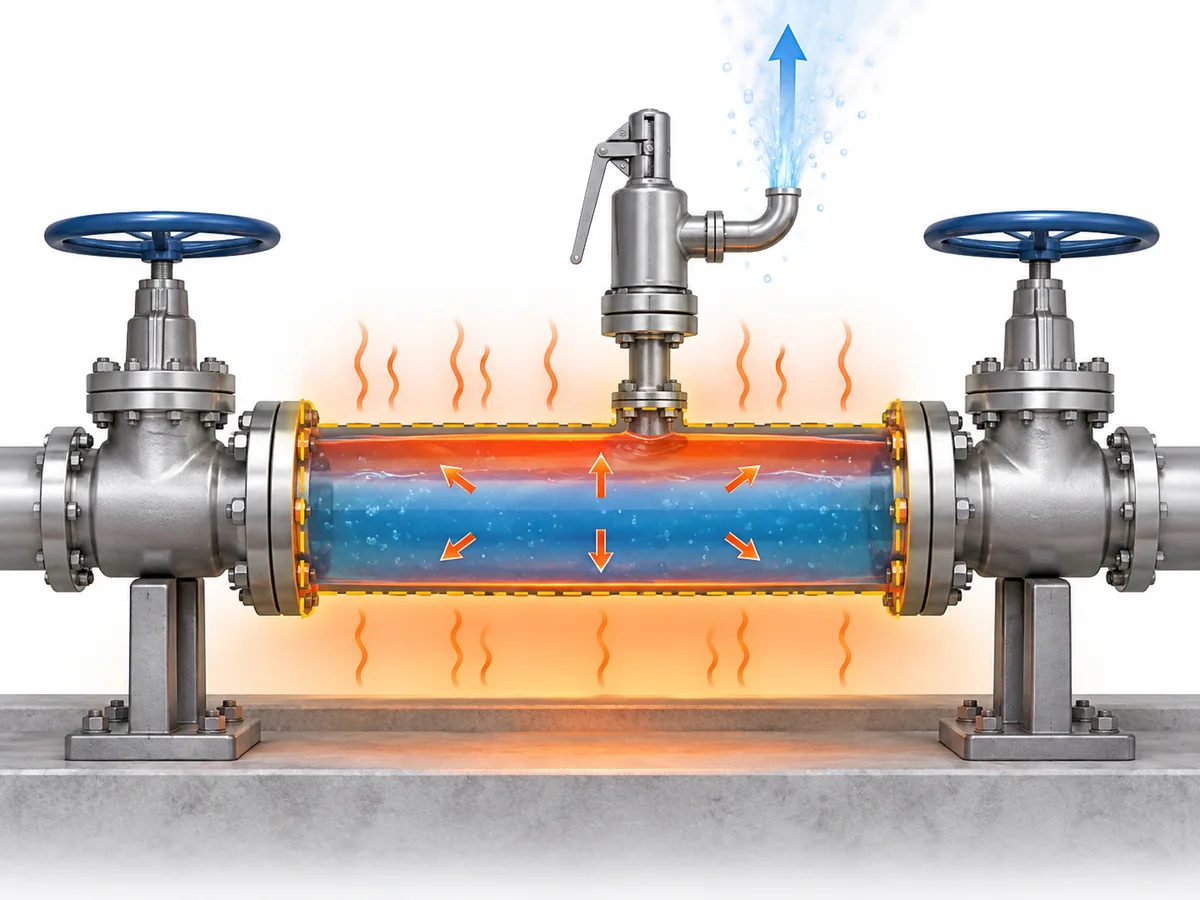
السوائل أقل قابلية للانضغاط بكثير من الغازات. عندما يكون حجم معزول ممتلئًا
بالسائل بشكل كبير، فإن الحجم الإضافي من السائل الناتج عن التسخين قد يتحول بالتالي إلى
ارتفاع حاد في الضغط ما لم يكن لدى النظام طريقة كافية لاستيعابه أو تنفيسه.
إدخال الحرارة يعتمد على التركيب. حسب النظام، قد تشمل المصادر ذات الصلة
التسخين المحيطي أو الشمسي، أو التتبع الحراري، أو منطقة محيطة مسخنة، أو معدات
معالجة مجاورة. وجود أحد هذه المصادر لا يجعله تلقائيًا الحالة
الحاكمة؛ يجب إثبات الحالة المعقولة للتركيب الفعلي.
الإغلاق المحكم لا يعني مجرد “عدم وجود تدفق”.”
بل يعني أن النظام يمكن أن ينشئ حدود ضغط سائل مقيدة تحت ظروف
قد يتحدى فيها التمدد الحراري تلك الحدود.
هذا هو الشرط الذي يجب تحديده قبل حساب مقاسات أو اختيار جهاز تنفيس.
هل يحتاج كل قسم سائل محصور إلى صمام تنفيس حراري مخصص؟
ليس تلقائيًا.
تحديد سيناريو تمدد حراري موثوق يثبت أن خطر الضغط الزائد
يحتاج إلى استجابة هندسية مناسبة. ولا يثبت من السيناريو وحده أن
ترتيبًا واحدًا محددًا لصمام تنفيس حراري مخصص هو الحل المقبول الوحيد.
| سؤال هندسي | ما الذي تم إثباته فعليًا؟ |
|---|---|
| هل يمكن أن ينحصر السائل وترتفع درجة حرارته؟ | يوجد سيناريو محتمل للتمدد الحراري. |
| هل يمكن أن يمثل هذا الشرط تحديًا لحدود الضغط المحمية؟ | يجب تقييم الحماية من الضغط الزائد. |
| هل يجب أن يكون الحل صمام تنفيس حراري مخصص؟ | يعتمد ذلك على استراتيجية الحماية المعتمدة وأساس المشروع. |
| هل صمام معين مناسب؟ | يتطلب ذلك مهمة تشغيل محددة بالإضافة إلى أدلة خاصة بالمنتج. |
اعتمادًا على النظام والأساس الهندسي المعمول به، قد تشمل الحماية
جهاز تنفيس ضغط أو ترتيبًا هندسيًا آخر يمنع نشوء ضغط
غير مقبول. ولا ينبغي تعميم حل مقبول لخدمة أو اختصاص قضائي معين على
كل خط معالجة.
تُعد مواصفة API Standard 521 مرجعًا على مستوى النظام لتنفيس الضغط وتخفيض الضغط في المنشآت النفطية,
والبتروكيماوية ومنشآت LNG والمنشآت ذات الصلة. ويدعم نطاقها تقييم سيناريو التنفيس
والنظام قبل اعتبار اسم المنتج قرار التصميم.
معلومات معيار API 521.
قد تضلل المصطلحات قسم المشتريات أيضًا. صمام تنفيس الضغط الهيدروستاتيكي
يُستخدم في بعض الصناعات للأجهزة التي تحمي الأنابيب حيث يمكن احتجاز السائل
بين صمامات الإغلاق. هذا التداخل العملي في المصطلحات لا يجعل
“صمام تنفيس هيدروستاتيكي” و“صمام تنفيس حراري” متبادلين عالميًا عبر
كل مائع أو كود أو صناعة.
تأكيد السيناريو → تحديد استراتيجية الحماية → التحقق من أساس المشروع/الكود المعمول به
→ اختيار الجهاز والتحقق منه.
لسياق أوسع للمعايير، راجع
دليل أنظمة تنفيس الضغط وفق API 521 من ZOBAI
.
ما الذي يحدد معدل التنفيس الحراري المطلوب وسعة الصمام؟
يجب اختيار صمام تنفيس التمدد الحراري بناءً على
معدل التصريف المطلوب, ، وليس بناءً على قطر الأنبوب أو مقاس معتاد
“صمام حراري صغير”.
في حالة التمدد الحراري للسائل المملوء، تعتمد متطلبات التنفيس على
الظروف الحرارية وعلى خصائص المائع التي تحدد كيفية استجابة السائل مع تغير
درجة الحرارة. وبمجرد تحديد معدل التصريف المطلوب، يعتمد حساب مقاس الصمام الفعلي أيضًا
على ضغط التنفيس المطبق ودرجة الحرارة وظروف الضغط الخلفي عند المخرج
وحالة المائع.
الظروف الحرارية المعتبرة → خصائص المائع المطبقة → معدل التصريف المطلوب
→ ضغط التنفيس وظروف المخرج → طريقة حساب المقاس المطبقة
→ مساحة/سعة التدفق المطلوبة → التحقق من سعة الصمام المرشح.
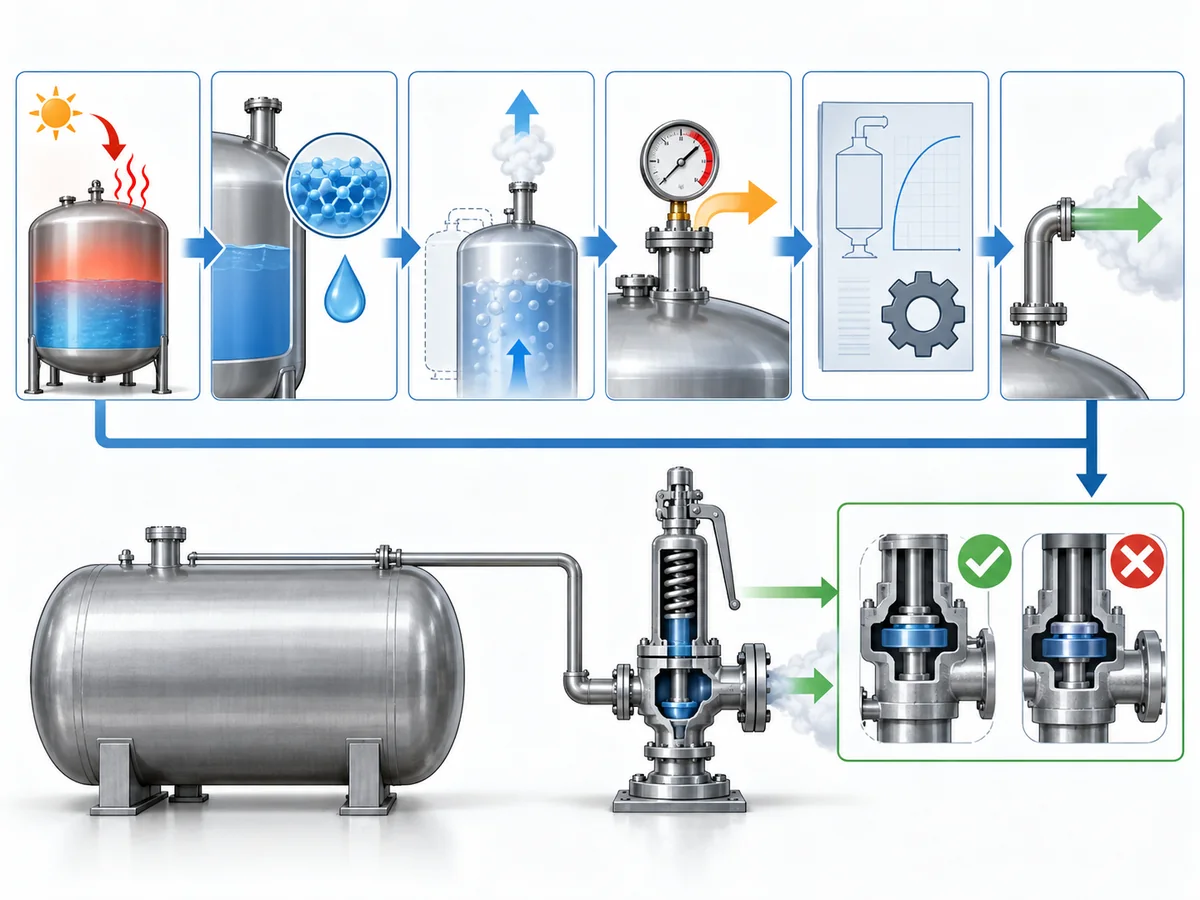
هناك اختصاران يجدر رفضهما. حجم الوصلة ليس سعة:
قد يتلاءم الصمام ميكانيكيًا مع الخط بينما يفتقر إلى السعة المطلوبة لحالة
التنفيس. و “غالبًا ما يكون تدفق التنفيس الحراري صغيرًا نسبيًا” ليس
طريقة: حتى الواجب المتواضع يجب تحديده قبل قبول أي صمام
مرشح.
تتناول API 520 الجزء الأول تحديدًا حساب واختيار أجهزة تنفيس الضغط
ضمن نطاقها.
معلومات API 520 الجزء الأول.
للاطلاع على سير عمل الحساب العام التفصيلي بدلًا من تكراره هنا، راجع
ZOBAI’s safety valve sizing and certified relieving capacity guide
.
The practical inputs for this thermal-expansion case include:
- the protected section and relevant trapped volume;
- the credible thermal condition or heat input;
- fluid identity and the physical properties required by the applicable calculation;
- ضغط ودرجة حرارة التنفيس؛;
- the required relieving rate;
- expected back pressure; and
- the fluid-state assumption used by the sizing method.
Only after the required duty has been established should the selected valve’s documented
capacity be compared against it.
Thermal relief is duty-sized, not simply small-sized.
How Should the Set-Pressure Basis Be Established?
Set pressure should be derived from the pressure boundary being protected,
not copied from normal operating pressure or selected from a generic percentage rule.
That separation is consistent with recognized relief-device specification practice:
operating pressure, set pressure, relieving/design temperatures, allowable overpressure,
back pressure and required capacity are treated as distinct inputs rather than
interchangeable values.
Baker Hughes pressure-relief valve specification guidance
.
| مصطلح الضغط | Role in the thermal-relief decision |
|---|---|
| ضغط التشغيل | The pressure the system normally experiences. |
| Protected design / allowable pressure basis | The applicable pressure boundary for the piping or equipment being protected. |
| ضغط الضبط | The specified pressure associated with the relief device beginning its defined opening action. |
| ضغط التنفيس | The pressure condition used for relief sizing or capacity assessment. |
| الضغط الخلفي | Pressure acting on or downstream of the valve outlet. |
Those values are related, but they are not interchangeable. Identify which piping and
components lie inside the blocked-in boundary, then establish the governing pressure basis
under the applicable design code, equipment rules and project specification before
assigning the valve set pressure.
Scope discipline matters here. A pressure rule written for a vessel should not automatically
be transplanted into generic process piping, and a regulation written specifically for LPG,
ammonia or another service should not be generalized to unrelated fluids or jurisdictions.
This article therefore does not create a universal rule such as
“set the thermal relief valve at a fixed percentage above operating pressure.”
Where a numerical relationship is prescribed, it belongs to the applicable equipment,
code, project and jurisdictional basis.
For an RFQ, set pressure should be treated as the result of a protected-system engineering
decision, not merely as a field to complete on a vendor datasheet.
Why the Relieving Fluid State Must Be Checked, Not Assumed
A line can be liquid-filled before the relief event without remaining a simple
single-phase liquid system throughout the complete relieving path.
Relief-valve engineering guidance distinguishes straightforward liquid sizing from cases
in which subcooled liquid can flash as pressure falls through the valve. That makes the
relieving-state check a real sizing boundary rather than a semantic detail.
LESER engineering guidance.
As pressure changes through the valve and downstream piping, the relationship between fluid
pressure and temperature can change. Under some conditions, the liquid remains adequately
subcooled and a liquid-sizing basis remains appropriate. Under others, flashing or a more
complex phase condition may need to be considered.
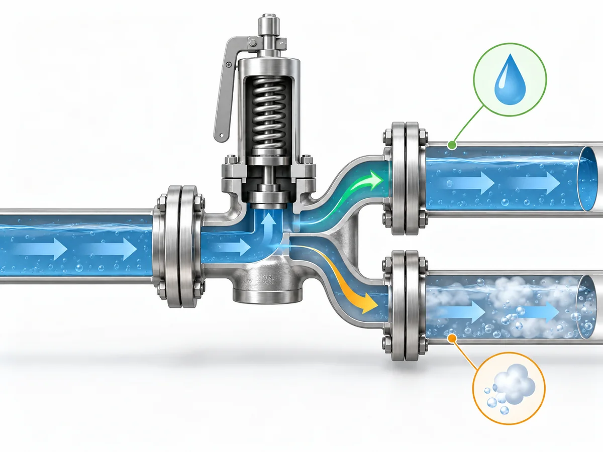
At the relevant relieving pressure and temperature—and as pressure falls through the
valve and outlet system—does the fluid remain in the phase assumed by the sizing method?
If the assumed phase remains valid, the case can continue under the appropriate liquid-sizing
methodology. If meaningful phase change occurs, the required inputs and sizing treatment can
change. That does not mean every thermal-expansion case is two-phase; it means the phase
assumption should be verified rather than inherited from the normal operating description.
A procurement description such as “liquid service, thermal relief”
therefore does not by itself prove the relieving-state assumption required for final sizing.
This article treats initial phase و relieving phase
as related but separate engineering inputs.
Why Discharge Routing and Back Pressure Are Part of the Relief Decision
A correctly selected valve is not enough if the installed relief path cannot perform
under the defined scenario.
Protected section → valve inlet → relief device → outlet piping → disposal or recovery destination.
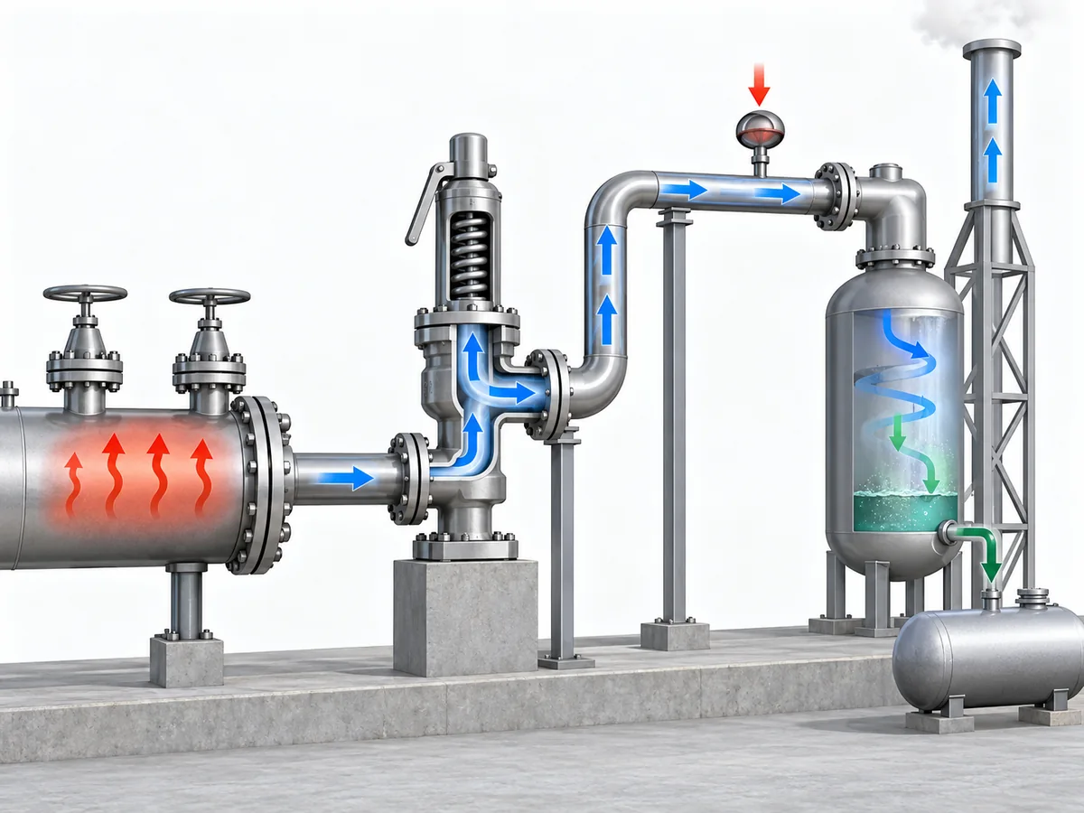
The review should establish where the relieved liquid will go, whether that route remains
available during the relief case, and what pressure the downstream system will impose on
the valve.
Back pressure can influence relief-valve behavior and available capacity, depending on the
valve design and system. Emerson’s pressure-relief-valve engineering handbook treats back
pressure as a factor that can affect opening or reseating behavior, stability and capacity,
so it belongs in candidate verification rather than being left as a post-purchase piping detail.
Emerson Pressure Relief Valve Engineering Handbook
.
For a deeper treatment of that interface, see
ZOBAI’s back-pressure and bellows engineering guide
.
The destination itself is service-dependent. A small expected thermal-relief rate does
not prove that unrestricted atmospheric discharge is acceptable. Conversely, a closed
return, drain or recovery system is not automatically suitable if it imposes unacceptable
back pressure or can be isolated when relief is required.
ISO 23251 provides an international pressure-relief-system framework for petroleum,
petrochemical and natural-gas industries. Its current 2019 edition explicitly supplements
API 521 6th Edition, so project teams should confirm the adopted standard set rather than
silently treating different editions as textually equivalent.
ISO 23251 information.
Where can the relieved fluid go without compromising either safe disposal or the valve’s
ability to perform its relief function?
Detailed flare design, closed-header hydraulics and valve-architecture thresholds belong
to separate engineering work. This article only needs to establish that the outlet system
forms part of the relief decision.
What Information Belongs in a Thermal-Relief RFQ or Engineering Review?
A technically useful RFQ should describe the protected system and relief duty,
not simply request a valve by nominal size.
Separate the process inputs from the supplier verification:
| Buyer / engineer should define or assign | Supplier / candidate should confirm |
|---|---|
| Protected piping or equipment boundary | Exact valve configuration offered |
| Fluid and relevant composition | Wetted-material, seat and seal suitability |
| Normal fluid state | Pressure-temperature suitability |
| ضغط التشغيل ودرجة الحرارة | Available set-pressure capability |
| Governing protected-pressure basis | Documented capacity for the specified duty |
| Credible thermal condition or heat source | Selected flow area or valve size |
| Required relieving rate, or responsibility for determining it | Effect of specified back pressure on the candidate |
| Relieving-phase assumption | Connection and pressure-class suitability |
| الضغط الخلفي المتوقع | Applicable inspection or test documentation |
| Relief destination | Requested conformity documentation, where applicable |
| Applicable project code or specification | Deviations, limitations and unresolved points |
Required relieving capacity is not the same as connection size.
One is a process-protection requirement; the other is primarily an installation characteristic.
Required capacity is also not the same as compliance evidence.
Capacity documentation addresses the flow-performance question under the applicable basis.
Material certificates, inspection records or other project-required conformity evidence
answer different procurement questions.
A supplier should not have to guess the relief scenario. If the protected pressure basis,
thermal condition, required relieving rate, fluid state or expected back pressure remains
undefined, those gaps should be resolved before a proposed valve is treated as an approved
candidate.
Can the proposed valve be traced back to a defined thermal-expansion duty, protected
pressure boundary, relieving state and outlet condition—and does the supplier evidence
address each of those requirements?
If not, the candidate is not ready for approval merely because a catalogue uses the words
تنفيس حراري أو hydrostatic relief.