Diagnosticare l'ostruzione delle valvole di sicurezza camiciate individuando la restrizione, verificando l'apporto di calore, distinguendo i meccanismi di deposito e raccogliendo evidenze prima della riparazione.

L'intasamento dell'otturatore di una valvola di sicurezza camiciata può verificarsi anche quando il corpo è dotato di camicia di riscaldamento.
A valvola di sicurezza camiciata può comunque intasarsi perché una camicia di riscaldamento affronta solo una parte del problema dell'intasamento. Può ridurre il rischio di solidificazione o di aumento della viscosità legato alla temperatura nella zona che riscalda efficacemente, ma non garantisce che ogni superficie a contatto con il processo, componente mobile, zona di uscita o tubazione adiacente rimanga priva di ostruzioni. Depositi di processo, materiale estraneo, apporto termico locale insufficiente o ostruzioni al di fuori della zona efficacemente riscaldata possono produrre sintomi simili.
Ciò rende “la valvola è intasata” un sintomo, non una diagnosi. Prima di aumentare il calore, pulire la valvola, modificare l'installazione o sostituire il dispositivo, occorre innanzitutto stabilire dove si trova l'ostruzione e quale meccanismo potrebbe ragionevolmente averla creata in quel punto. La sequenza utile di risoluzione dei problemi è: localizzazione → meccanismo plausibile → evidenza discriminante → azione successiva controllata.
Intasamento della valvola di sicurezza camiciata: individuare l'ostruzione
La prima domanda di troubleshooting non è “Che cosa causa l'intasamento?”. È “Dove si trova l'ostruzione?”
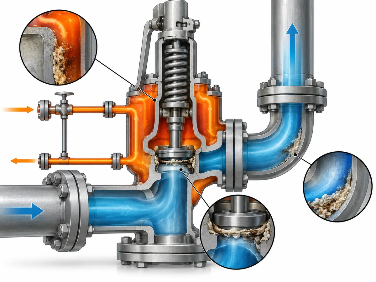
Una valvola di sicurezza camiciata comprende due domini funzionali molto diversi: il lato processo, che deve rimanere disponibile per lo sfioro, e il circuito della camicia o di riscaldamento, utilizzato per influenzare la temperatura. Un problema nel circuito di riscaldamento può consentire al fluido di processo di raffreddarsi, ma il circuito di riscaldamento stesso non è il percorso del flusso di sfioro. Mantenere separati questi due domini evita un comune errore diagnostico.
Sul lato processo, l'ostruzione può comparire attorno all'ugello o alla zona di tenuta. La documentazione del produttore per valvole di sicurezza camiciate e per servizio severo riconosce la possibilità di indurimento, solidificazione, cristallizzazione o deposito di materiale in queste aree. A seconda del design della valvola, contaminazione o depositi possono anche interferire con componenti guidati o altri componenti mobili e influenzare il movimento previsto o la richiusura.
La geometria interna esatta dipende dal modello, quindi un articolo di troubleshooting non deve presumere che ogni valvola camiciata riscaldi o esponga gli stessi componenti. Per una valvola installata, il disegno, la scheda tecnica o la documentazione del produttore sono la fonte corretta per determinare quali zone sono effettivamente camiciate e quali parti mobili possono essere esposte al fluido di processo.
L'ostruzione può esistere anche all'esterno del corpo valvola. La connessione di uscita o tubazione adiacente può operare in condizioni termiche diverse rispetto alla zona camiciata. Se il materiale rimane fluido attraverso la parte riscaldata della valvola ma si raffredda più a valle, il problema osservato può essere una questione termica a livello di installazione piuttosto che la prova che il corpo camiciato stesso sia difettoso.
Questo approccio che parte dalla localizzazione cambia la domanda successiva. Un deposito sul bocchello, materiale che interferisce con un componente guidato e materiale solidificato più avanti nel sistema di scarico possono tutti essere descritti genericamente come “intasamento”, ma non stabiliscono lo stesso meccanismo né giustificano la stessa azione correttiva.
L'intasamento termico inizia dove il riscaldamento efficace viene meno
Il camiciamento è una caratteristica di gestione termica. La sua presenza non dimostra di per sé che un calore adeguato raggiunga ogni punto rilevante.
Questa distinzione è particolarmente importante con fluidi la cui scorrevolezza varia fortemente con la temperatura. Se il materiale di processo può indurirsi, cristallizzare, rapprendersi o diventare molto più viscoso raffreddandosi, la domanda di troubleshooting non è semplicemente se la valvola sia camiciata. È se la regione di processo interessata sia rimasta nelle condizioni termiche richieste da quel servizio.
Diverse variabili possono cambiare questa risposta.
La prima è la copertura. I progetti dei produttori differiscono. Alcune soluzioni di camiciamento concentrano il riscaldamento attorno al corpo valvola o alla zona di uscita; altri progetti offrono aree riscaldate aggiuntive per servizi gravosi. Il tracciamento o il camiciamento della tubazione di processo non può quindi essere automaticamente considerato prova che la zona della sede valvola, i componenti interni o il percorso di scarico ricevano una protezione termica equivalente.
La seconda variabile è actual heat delivery. For a steam-heated installation, heat transfer depends on the condition and operation of the heating system, not merely on the presence of steam connections. General steam-heating practice shows that steam and condensate behavior, drainage, operating condition, and the arrangement of the heating circuit affect heat transfer. The exact significance of these factors must be evaluated against the installed valve and heating system rather than converted into a universal pressure, temperature, or flow rule.
The third variable is time. A process that remains fluid during steady production may behave differently during a prolonged standby or shutdown. A valve may be adequately heated in normal operation yet experience a different temperature history when process flow stops, the heating medium is interrupted, or surrounding equipment cools. A repeated plugging event after a particular shutdown pattern is therefore useful evidence, but it is still a clue rather than proof of one mechanism.
The fourth variable is the thermal boundary around the valve. The jacketed body, inlet pipe, outlet pipe, insulation, and any heat-tracing system should not be mentally collapsed into one heated object. They may have different thermal behavior. If troubleshooting confirms that the valve body remains adequately heated while a nearby process or discharge region cools, the next engineering task belongs to the broader piping and thermal-management arrangement.
A representative example illustrates the distinction. Imagine a valve body that remains heated while an adjacent region of the discharge path cools during standby. Material may remain mobile inside the heated region yet become more viscous or solidify farther downstream. The visible symptom is still “plugging near a jacketed safety valve,” but adding more heat to the valve body would not automatically address the actual restriction location. This is an illustrative engineering scenario, not a recorded project case.
The practical lesson is simple: jacket present e effective thermal protection at the restriction location are not equivalent statements.
Plugging Mechanisms Can Overlap
Temperature is important in jacketed service, but not every deposit is evidence of insufficient heating.
For temperature-sensitive media, several supported mechanisms deserve consideration. Material may harden or solidify as it cools. Crystallizing media may form solids in local regions where temperature or concentration conditions permit crystallization. Highly viscous material may become increasingly difficult to move as temperature falls. These mechanisms are directly relevant to why heating jackets are offered for certain relief-valve applications.
Particulate contamination and foreign material form a different branch of the diagnosis. Manufacturer troubleshooting literature documents cases where foreign material or deposits interfere with seating or guided components. A hotter jacket will not necessarily remove a contamination problem whose controlling mechanism is solids carried by the process.
These mechanisms can also interact. Temperature may change viscosity and deposit behavior at the same time that suspended material is present. A deposit found after disassembly may therefore be the result of more than one operating condition. Its appearance alone should not be used to declare that heating failure was the root cause.
More chemistry-dependent mechanisms require tighter boundaries. Polymerization, coking, decomposition, or other reaction-driven deposits can be relevant in some processes, but they should not be presented as generic causes of jacketed safety-valve plugging. Whether one of these mechanisms is credible depends on the actual medium, composition, contaminants, temperature history, residence time, and process conditions.
The same caution applies to exact solidification or crystallization temperatures. A generic article should not assign a transition temperature to an unspecified medium or assume that a familiar commercial material always behaves the same way. The real service composition and operating data control that judgment.
This is why “increase the jacket temperature” is not a universal troubleshooting answer. If the cause is foreign material, a process-derived deposit, a restriction outside the heated region, or a chemistry-dependent mechanism, more heat may fail to address the root problem and could introduce a different process concern.
The useful distinction is not simply thermal versus nonthermal. It is: What material is present, where did it accumulate, what operating history preceded the restriction, and which mechanism is actually consistent with that evidence?
Diagnose the Cause From Evidence, Not From the Word “Plugging”
A useful troubleshooting process should reduce uncertainty rather than convert a symptom into a confident diagnosis.
Start with the physical evidence. If the restriction location is unknown, do not skip directly to the cause. If the valve has been removed and inspected under the applicable maintenance procedure, record where deposits or foreign material were found. If the issue appears to be in adjacent piping rather than the valve itself, preserve that distinction.
Then compare that evidence with the process and temperature history. What medium was in service? What was its phase and known composition? Does its flowability depend strongly on temperature? Were there shutdowns, prolonged standby periods, abnormal temperature excursions, or changes in the heating system before the problem appeared?
For a jacketed installation, also verify what the heating system was actually doing. Useful information includes the heating medium, available pressure and temperature data, the jacket connections and coverage, and how surrounding piping or equipment was being kept hot. The purpose is not to prove a failure from one reading. It is to determine whether the proposed thermal mechanism is consistent with the real installation.
Operating and maintenance history adds another layer. A restriction discovered after a relief event may raise different questions from one that develops repeatedly during long standby periods. A valve that has experienced repeated contamination may require a different investigation from one in a clean service that solidifies predictably when cold.
The following matrix can help organize the evidence without turning observations into automatic diagnoses:
| Osservazione | Plausible interpretation | What to check next | Cosa non dimostra |
|---|---|---|---|
| Hardened or crystalline material around the nozzle or seating region | Cooling, solidification, crystallization, or another deposit mechanism may be involved | Medium/composition, temperature history, actual jacket coverage and heat condition | That the jacket itself failed |
| Valve body is heated but restriction appears farther downstream | Adjacent piping may have a different thermal condition | Outlet arrangement, insulation/tracing scope, operating and standby temperatures | That more body-jacket heating will solve the problem |
| Foreign or particulate material is found around guided or moving parts | Contamination or process solids may be interfering with movement | Source of solids, deposit observations, inspection and service history | That temperature is the controlling cause |
| Problems recur after shutdown or long standby | Thermal history may be contributing | Heating continuity, cooling duration, medium behavior during shutdown | That shutdown temperature alone is the root cause |
| Jacket is installed but its operating condition is not documented | Adequacy of heat delivery is unknown | Heating-medium data, jacket condition and installation records | That the jacket is ineffective |
| Deposits are present but composition is unknown | Several thermal or process mechanisms remain possible | Deposit characterization and actual process composition where appropriate | Polymerization, coking, crystallization, or any other specific mechanism |
The goal is not to rank these causes by probability. There is no defensible universal ranking for an unspecified process, valve design, and heating arrangement. Instead, each observation should eliminate some explanations, strengthen others, and identify the information still missing.
That distinction matters because plugging can affect more than cleanliness. Manufacturer literature documents cases where solidified or foreign material can interfere with expected opening, full movement, closing, or reseating. That is enough to make a suspected restriction an engineering concern.
È prescrive enough to calculate a generic loss of relieving capacity. Connection size is not capacity, and the visible amount of deposit is not a certified flow calculation. Quantifying the effect of a restriction requires the actual geometry, fluid and relieving conditions, valve data, and the applicable capacity basis. A statement such as “20% blockage means 20% less capacity” would not be justified.
For the same reason, an external appearance or nominal connection match is not a sufficient basis for replacement. If the troubleshooting process eventually leads to valve replacement, the replacement review must still address the applicable set pressure, required and documented relieving capacity, service conditions, configuration, materials, installation interfaces, back-pressure conditions where relevant, governing requirements, and documentation.
Confirm the Cause Before Cleaning, Repair, or Replacement
The purpose of troubleshooting is to define the next engineering action, not to prescribe an intervention before the mechanism is known.
Before a maintenance or engineering review, assemble a compact evidence package. The most useful inputs for this problem are usually:
- process medium, phase, and known composition;
- normal operating temperature and relevant shutdown or standby temperature history;
- any known temperature-sensitive behavior of the medium;
- heating medium and available jacket operating data;
- valve manufacturer, model, datasheet, or drawing when available;
- the regions that are actually jacketed;
- inlet and outlet arrangement, insulation, and heat-tracing scope;
- exact location of the observed restriction or deposit;
- inspection photographs or observations where available;
- valve lifting/discharge history;
- shutdown/startup history;
- maintenance and prior cleaning history;
- required relieving capacity or existing sizing basis if repair or replacement is being considered;
- applicable project specification or maintenance requirements.
This information helps separate an identification problem from an engineering-acceptance problem. A photograph may help identify where material accumulated, but it does not establish remaining relieving capacity. A matching connection size may identify a replacement candidate, but it does not establish interchangeability. A jacketed body may confirm that thermal management was intended, but it does not prove that the installed heating arrangement was effective under the event being investigated.
Corrective action should follow the confirmed cause as closely as the available evidence allows. If inadequate local heating is supported, the heating arrangement needs engineering review. If the restriction is outside the jacketed region, the broader piping and thermal-management system becomes the relevant boundary. If process solids or foreign material are involved, the source of those deposits must be investigated rather than automatically increasing heat. If the deposit mechanism cannot yet be identified, the correct next step is additional inspection or process review—not a more confident assumption.
Richiedi una revisione ingegneristica
If the plugging mechanism is still uncertain, send the process medium and operating-temperature history, heating-medium conditions, valve identification or datasheet, inlet/outlet arrangement, jacket and tracing coverage, inspection findings, and maintenance history for review. If replacement is being considered, include the existing sizing/capacity basis and project requirements as well.
The objective is not to select a remedy from the word “plugging.” It is to identify the restriction, establish the most defensible mechanism, and then make the maintenance, thermal-management, or replacement decision from evidence.