了解如何检查先导式安全阀的过滤器、导压管和密封件,并根据回装投用前所需的验证依据匹配功能试验。

先导式安全阀的维护不能把先导阀当作
仅仅是螺栓连接在主阀上的附件。先导阀、过滤器、感测
或供压接口、控制管路、密封件与主阀共同构成一个压力控制
系统。即使主阀阀体本身看似可用,污染、泄漏、节流或压力
通路恢复不当仍可能产生影响。
第二个维护误区是把每次维护后的“测试”都视为等效。
先导阀整定压力检查、密封面泄漏试验、装配泄漏试验、,
整机功能试验与排量试验所回答的是不同
问题。PASS 结果仅在其对应试验的范围内有效。
因此,本文遵循两条原则:
- 检查阀门上实际安装的先导/控制回路。
- 在回装投用前,使试验与所需证据相匹配。
本文采用 先导式安全阀 作为其工作术语。
制造商与标准文件也可能使用
先导式泄压阀, POSV 或 POSRV.
ISO 4126-4 是专门针对先导式安全阀的 ISO 产品标准;;
ISO 指出其为产品标准,而非应用标准。因此
不能替代特定型号的维护手册、业主程序或
当地法规的恢复投用要求。参见
ISO 4126-4.
如果操作顺序本身尚不明确,参见
先导式安全阀的工作原理.
维护前,确认阀门配置和拆检状态
在清洗过滤器、断开管路或更换密封件之前,,
准确确认您所操作的具体主阀、先导阀及感压布置方式。
先导式设计在以下方面存在差异:进口压力如何到达先导阀、感压
是内置式还是远程式、控制腔/控制压力如何引入、过滤器安装在何处
以及哪些部件作为独立组件进行维护或测试。
适用于一种布置方式的维护步骤不应
自动套用到另一种布置方式。例如,Anderson Greenwood 727 系列手册,
包含内置感压、远程感压及阻尼器布置,并针对这些配置给出了具体
说明。Baker Hughes 的 Consolidated 2900-40 手册
同样区分远程传感和传感环选项。这些制造商
示例支持相同的通用维护规则:在打开或恢复之前
确定确切的压力路径。参见
Anderson Greenwood 727 系列维护说明
和
Baker Hughes Consolidated 2900-40 POSRV 手册.
首先确认:
- 主阀和先导阀标识,包括获取正确程序和零件所需的型号/序列号信息;;
- 适用的制造商维护说明和业主程序;;
- 传感布置,包括远程传感、缓冲器或现场测试连接(如使用);;
- 与污染、腐蚀、弹性体兼容性和沉积物相关的工艺介质和工况;;
- 阀门被拆卸、检查或开启的原因;;
- 清洗或拆卸前的原始状态;以及
- 相关的前次测试或维护记录(如有)。
承压系统或先导系统上的作业必须遵循适用的
工厂和制造商的隔离与泄压程序。例如,Series 727
手册警告,在阀门操作前必须对系统进行泄压
拆卸或解体,并注意流体可能残留在先导腔室内
先导式安全阀的。这是针对具体产品的操作说明,而不是
通用的隔离顺序。现场隔离方案必须与实际
安装方式和危害相符。
保留 拆卸前原始状态 在清洗之前,先清除会破坏有用
证据。堵塞的过滤器、传感接头内的腐蚀产物、以及……周围的泄漏
a pilot connection, an incorrectly connected line or an unexpected deposit can
explain why the assembly behaved abnormally. API RP 576 covers inspection and
repair practices for pressure-relieving devices, including pilot-operated PRVs,
and its current API catalog entry emphasizes inspection/repair practices intended
to support proper device performance. See
API RP 576 in the API refining catalog.
有关更全面的整阀维护计划、检验计划以及
拆卸前/回装后状态记录,请参阅
安全阀维护与检查指南.
The present article stays focused on the pilot/control path and the evidence
needed after work on filters, tubing, seals and functional tests.
维护决策: Do not diagnose or replace the component
until the configuration around it is known well enough to explain what pressure
the component should receive, retain, vent or transmit.
将过滤器作为先导控制回路的一部分检查,而非孤立部件
On pilot-operated valve designs that use a filter in the sensing or pilot-supply
path, filter condition can tell you more than whether the filter itself needs
attention. A filter is part of the pressure path feeding the pilot system.
If that path is restricted, the problem is not “dirty hardware” in the abstract;
it is whether the pilot receives and responds to the pressure signal in the way
the design requires.
过滤器被污染并不能 不 prove that the pilot is blocked.
It does provide evidence that the same contaminant may have reached adjacent
passages, fittings or pilot components. The maintenance response should therefore
应沿污染路径继续排查,而不是在第一个脏污部件处就停止。
制造商说明也表明,为什么不存在通用的过滤器规则。
在 Anderson Greenwood 727 系列手册中,主阀过滤器组件需
拆下进行清洗和检查,若未损坏可重复使用,,
而相应的过滤器接口密封件则需丢弃并更换。其他阀门
系列可能采用不同的过滤器布置和更换规则。正确的
做法是针对具体阀门配置所规定的操作,而不是“总是重复使用”
或“总是更换”。”
| 过滤器检查结果 | 应采取的整改措施 |
|---|---|
| 清洁且无损伤 |
继续完成其余所需的先导路径检查。过滤器清洁 并不能证明传感通道、接头、先导阀座或控制 连接处无堵塞或泄漏。 |
| 污染严重 |
检查所连接的控制路径是否存在相关污染或 在条件允许时,清洁前先记录污染物类型并做好限制说明。 |
| 按适用规程判定为损坏或不合格 |
遵循特定型号的更换要求,并核实正确的 更换部件。 |
| 反复出现严重污染 |
审查为什么污染物持续进入先导系统,而不是 把每次过滤器维护当作孤立的维护事件来处理。 |
维护周期也存在同样的边界。API RP 576 是检验实践
参考标准,但无论是该标准的范围,还是本文所查阅的制造商手册,
都不支持对所有先导式安全阀采用统一的过滤网清洗周期。
周期应依据适用规程、工况严苛程度、污染
历史及业主检验计划确定。
因此,过滤网状态可作为判断先导系统所处环境
的诊断依据,而不仅仅是日常清洁事项。
检查传感与控制管路是否堵塞、泄漏及复装错误
先导式安全阀周围的每根小管并非都具有相同用途。
根据设计不同,技术文件可能区分取压管、,
先导阀供压接口、阀罩/控制管路、远程取压接口、排放
connection and field-test connection. Before loosening a fitting, identify what
pressure that line is supposed to communicate and to which component.
Manufacturer maintenance instructions reinforce this point. The Series 727 manual
calls for inspection of remote-sense and snubber fittings for blockage in applicable
configurations. Baker Hughes’ 2900-40 manual shows that remote sensing is its standard
pilot pressure connection while a sensing-ring option changes the pickup location.
These are design-specific arrangements, but together they show why “the tubing looks
similar” is not enough to establish correct routing.
因此,管路问题应按失效模式分别排查。
| 发现 | 重要性 | Maintenance check |
|---|---|---|
| Restriction or blockage |
The intended pressure signal or pilot-supply path may be delayed, attenuated or prevented from reaching the intended component. |
Inspect the affected passage, fitting, snubber/filter and connected pilot components using the applicable procedure. |
| Leakage |
Pressure integrity in the sensing, dome or control path may be lost. The effect depends on where the leak is located in the circuit. |
Identify the leaking joint/component and perform the specified post-assembly leakage check after correction. |
| Kink, corrosion or mechanical damage |
The flow area or mechanical integrity may no longer match the intended configuration. |
Repair or replace with the specified material, size and routing from approved documentation. |
| Loose or incorrect reconnection | The valve may no longer sense, load or vent pressure through the intended path. |
Compare routing and connection points with the correct valve/manifold documentation, then leak-check the restored connection as required. |
| Unverified modification to a remote-sensing line | The sensing point or line characteristics may no longer match the engineered configuration. |
Return the arrangement for engineering/manufacturer review instead of normalizing the modification during maintenance. |
在技术采购中,清楚区分 restriction 和 泄漏
is important because the failure mechanisms differ. A restricted path can impair
pressure communication. A leak changes pressure integrity. The same symptom at the
valve may therefore have different causes, and the maintenance evidence needed to
close the job is not interchangeable.
Remote sensing deserves particular discipline. Do not shorten, resize, reroute or
reconnect a sensing line merely because the new arrangement physically fits. The
sensing point, line routing, fittings and any filter/snubber arrangement are part of
the approved pressure path.
Maintenance rule: Restore the documented pressure path, then verify
the applicable connections for restriction and leakage. If the approved routing
cannot be established, hold the valve for engineering or manufacturer review.
For maintenance closeout, “the tubing looks fine” is weaker evidence than confirming
that the correct pressure path has been restored and checked for the restriction and
leakage modes relevant to the applicable procedure.
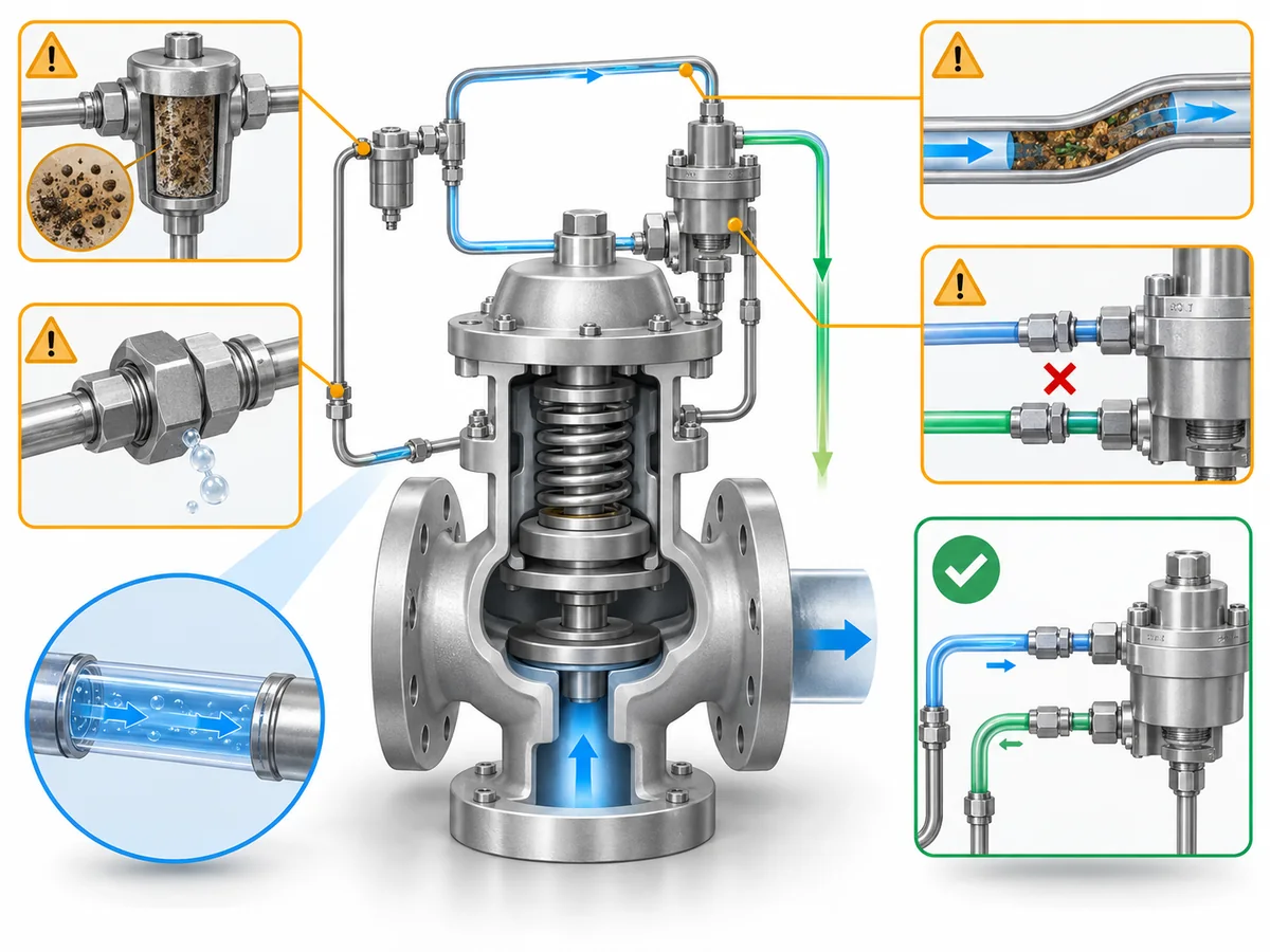
Evaluate Seals by Location, Condition and Service Compatibility
A seal decision should not begin and end with, “Does this O-ring look damaged?”
Pilot-operated valves contain seals in different functions: some retain dome or
pilot pressure, some seal the main valve, and some seal fittings or filter/manifold
joints. The consequence of damage, wrong material or wrong reuse decision depends
on where the seal sits in the pressure-control system.
Manufacturer repair instructions also do not treat every sealing component the same
way. The Anderson Greenwood Series 727 manual is a useful example: it allows the
filter assembly to be reused if undamaged, while it specifically tells the technician
to discard certain seals and other listed parts during the applicable repair steps.
Its repair kits are selected by valve model/serial information. That is exactly why a
generic “reuse if it looks good” rule is not defensible.
Two shortcuts should therefore be avoided:
Reuse every seal that still looks good.
和
Replace every seal on every pilot-operated valve whenever the valve is opened.
Instead, separate four questions.
1. Which seal is it?
Identify the location and function of the part. A pilot seat/seal, main-valve sealing
element, dome seal, filter-port seal and tubing/connection seal should not inherit the
same maintenance rule simply because each is called a “seal.”
2. Is the part and material correct?
Pilot-operated valve families can use different soft goods or metallic sealing
components for different pressure, temperature and process conditions. A replacement
should match the approved bill of materials or repair kit for the exact configuration,
not merely the apparent dimensions of the removed part.
For deeper material-selection context, see the
安全阀材质选择指南.
3. Is its condition acceptable?
Inspect for the damage modes addressed by the applicable manufacturer procedure:
cuts, extrusion, compression damage, wear, corrosion or deposit-related damage where
relevant. Appearance can identify physical deterioration, but it cannot prove the
material grade, prior chemical attack, or compatibility with the process.
4. Does the applicable procedure permit reuse?
This is separate from appearance. If the model-specific procedure requires
replacement during the applicable service operation, an apparently intact part is
not evidence for reuse. Conversely, a part the manufacturer permits to be cleaned,
inspected and reused should not be subjected to an invented universal replacement rule.
Seal decision sequence:
identity → function → approved material/configuration → physical condition →
permitted reuse/replacement → post-assembly leakage/functional verification.
Match the Functional Test to What You Need to Prove
A post-maintenance test is only as broad as its test scope. Instead of asking only,
“Did the valve pass?” ask:
Which test was performed, which part of the pilot/main-valve system did it
exercise, what acceptance basis was used, and what remains untested?
The standards have different roles. The current API catalog lists
API RP 576
as an inspection and repair practice covering pilot-operated PRVs;
API 527
addresses seat tightness, with the current API digital catalog listing API 527,
5th Edition, as the seat-tightness standard; and
API’s digital catalog
confirms the current API 527 entry.
ASME PTC 25-2023
is a performance test code for pressure relief devices and includes flow-capacity,
in-service and bench testing. These documents do not make a pilot set-pressure
check, seat-leakage test, assembly function test and capacity test interchangeable.
Manufacturer procedures make the same distinction at the equipment level. The
Anderson Greenwood Series 727 manual separates valve-assembly leak tests, pilot
set-pressure testing, and pilot/manifold internal leak testing. Its field test
procedure can verify pilot set pressure while the main valve does not cycle during
that procedure. That is strong evidence for a narrow but important maintenance rule:
a valid pilot test proves the pilot variable it actually exercises; it does
not automatically prove full main-valve operation or rated flow capacity.
| Check or test | What the result can support | What it does not automatically prove |
|---|---|---|
| Visual / configuration inspection | Visible condition, correct routing, part identity and assembly observations within the inspection scope | Set pressure, seat tightness, pilot response under pressure or rated flow capacity |
| Pilot/set-pressure verification | Pilot actuation or set-pressure behavior under the approved test method | Main-valve cycle, seat tightness, rated flow capacity or installed-system acceptance unless the procedure also tests those items |
| Seat-tightness / leakage test | Leakage performance for the seat or connections covered by the applicable test basis | Complete pilot/main-valve functional performance or flow capacity |
| Complete-assembly functional test | Defined operation/integrity of the assembled pilot and main valve under that procedure | Certified flow capacity unless capacity is actually tested under the required basis |
| Flow-capacity test | Flow performance under the defined test conditions | Correct field sensing-line routing, installation condition or every maintenance detail not represented in the test setup |
Pilot Set-Pressure or Pilot-Function Verification
On applicable designs, a field-test connection can allow pilot or set-pressure
behavior to be checked without reproducing every installed operating condition.
The Series 727 manual provides a field-test arrangement in which the pilot can be
pressurized and its pop/set behavior observed while the main valve does not cycle
during that procedure. That distinction should be preserved in the maintenance record.
A useful record is therefore not simply “Pilot test: PASS.” It should identify the
valve/pilot, the test method, the set-pressure basis being checked, the medium and
condition required by the procedure, and the function that was 不 exercised.
Do not import the Series 727 test pressures, warm-up periods or tolerances into another
valve family. Those values are model/procedure-specific. Use the correct manual and
project acceptance basis for the valve being maintained.
Seat-Tightness and Leakage Testing
Seat-tightness testing answers a leakage question. API Standard 527 is specifically
titled 压力泄放阀阀座密封性, and API’s current catalog
lists it for pressure-relief-valve seat tightness. That makes it appropriate evidence
for a seat-leakage conclusion within its scope—not for the broader statement that the
pilot/main-valve control system has been functionally verified.
Manufacturer procedures may also require connection or internal leak checks that are
outside the main-seat leakage question. The Series 727 manual, for example, separates
external-joint leakage, pilot/manifold internal seat tightness and other assembly checks.
The maintenance record should say which leakage path was tested.
Complete-Valve Functional Verification
A complete-assembly functional test is broader than a pilot-only set-pressure check
because it can exercise the interaction between the pilot and main valve under the
approved procedure. It is still bounded by the setup. If the procedure does not measure
rated flow capacity, the result should not be reported as capacity certification.
Baker Hughes’ Consolidated 2900-40 manual contains a distinct functional-testing
section and model-specific instructions for sensing/filter options. That is another
reminder that the exact functional test depends on the valve configuration. Use the
procedure for the actual assembly rather than creating a generic test sequence from
another manufacturer’s manual.
证据规则: A complete-assembly functional test proves the
functions included in that approved procedure—not every characteristic of the
installed relief system.
What a Field or Functional Test Does Not Prove
The largest post-maintenance interpretation error is to expand a narrow PASS result
beyond the question that was tested.
- Pilot set-pressure verification ≠ rated capacity evidence.
- Seat-tightness PASS ≠ complete functional proof.
- Complete-assembly functional test ≠ flow-capacity certification.
- Bench or field valve test ≠ proof that the entire installed sensing/control system is restored correctly unless that configuration is represented and checked.
For maintenance records and engineering review, document enough information to answer:
- What test was performed and under which approved procedure?
- What valve/pilot configuration was tested?
- What pressure path, seat, connection or operating function was evaluated?
- What acceptance basis was used?
- What did the test not evaluate?
- Does another maintenance question still remain open?
That makes the test result usable evidence instead of a generic “PASS” label.
A broader standards overview is available in the
安全阀标准指南.
Decide Whether the Valve Is Ready to Return to Service
Reassembly is not the same as maintenance closure. The return-to-service decision
should combine what was found, what was corrected, whether the correct pilot/control
path was restored, whether the required seals and parts were verified, and whether
the post-maintenance tests actually answer the questions created by the work.
该 PROCEED / HOLD / ESCALATE labels below are an engineering
screening framework used in this article. They are not API, ASME, ISO or regulatory
classifications and do not replace the valve owner’s, manufacturer’s or applicable
jurisdictional acceptance process.
| 筛选结果 | 在以下情况使用 |
|---|---|
| 通过 |
The applicable maintenance scope is complete, the documented configuration is restored, required parts/materials are verified, leakage or restriction concerns raised by the work are closed, and the required post-maintenance checks provide acceptable evidence for the questions they were intended to answer. |
| 暂缓 |
Relevant contamination, blockage, leakage, incorrect routing, uncertain seal identity/material, failed or ambiguous test response, or another unresolved maintenance condition remains. |
| ESCALATE |
The correct configuration cannot be established, repeated contamination suggests a broader service/system cause, test behavior conflicts with expected valve response, or the next step requires engineering/manufacturer input outside the validated maintenance scope. |
Before closeout, ask:
- Has a contaminated filter triggered the necessary inspection of the connected pilot path?
- Have sensing, supply, dome/control and field-test connections been restored to the documented configuration?
- Have relevant tubing/passages been checked for restriction and the reassembled pressure path checked for leakage as required?
- Are replacement or retained seals the correct parts/materials for the valve and permitted by the applicable procedure?
- Did the post-maintenance test actually examine the function that the maintenance work could have affected?
- Is each PASS result being used only within the scope of that test?
- Does any unresolved finding still require engineering, manufacturer or owner review?
A useful maintenance handoff contains more than “valve failed” or “valve repaired.”
Provide, where available, valve and pilot identification, relevant service conditions,
as-found observations, filter/tubing findings, components replaced or retained,
seal/soft-goods identification, tests performed, results/acceptance basis, and the
specific unresolved question if engineering review is still required.
That information helps the next reviewer distinguish a component maintenance issue
from a configuration, contamination, sensing-path or wider application problem.
Closeout principle: Maintenance is not complete merely because
the last part has been reassembled. It is complete when the relevant maintenance
questions have been closed with evidence appropriate to each question.
Frequently Asked Questions About Pilot Operated Safety Valve Maintenance
Can I clean a pilot filter and return the valve to service?
Not on the basis of the filter alone. Follow the exact manufacturer procedure for
cleaning or replacement, then consider whether the as-found contamination could also
have affected connected sensing/supply passages or pilot components. A clean filter
does not prove that the rest of the control path is unrestricted.
What should be checked after pilot sensing or control tubing is disconnected?
Confirm that the documented sensing/control path has been restored, the line is free
of relevant restriction or mechanical damage, and the reassembled connections meet
the required leakage/integrity checks. Remote-sensing lines should not be resized,
rerouted or reconnected to a different point without engineering or manufacturer approval.
Should every O-ring or seal be replaced whenever a pilot operated valve is opened?
There is no safe universal rule. Some manufacturer overhaul procedures require
specified seals or soft goods to be discarded and replaced, while other parts may be
inspected and reused under defined conditions. Identify the exact component, approved
material/part number and model-specific procedure before deciding.
Does a pilot set-pressure test prove the whole valve works?
Not necessarily. Some manufacturer field-test methods verify pilot set-pressure
behavior without cycling the main valve. The maintenance record should state what the
test exercised and what still requires another leak, functional or assembly check.
Does a seat-tightness test prove rated capacity?
No. Seat-tightness testing evaluates leakage under its applicable test basis.
Rated or certified flow capacity is a different performance question and should not
be inferred from a seat-tightness PASS result.
How often should a pilot operated safety valve be inspected?
A universal interval is not appropriate. Use the governing owner/jurisdictional
inspection program, the applicable manufacturer instructions, service severity,
contamination/corrosion history and prior as-found results. API RP 576 is an
inspection-practice reference for pressure-relieving devices, including pilot-operated PRVs.