Learn how chlorine condition, component materials, rupture-disc isolation, back pressure, and discharge containment affect safety valve specification.

Le valvole di sicurezza per servizio con cloro non devono essere selezionate semplicemente scegliendo un corpo valvola “resistente alla corrosione”. La condizione effettiva del cloro, i componenti che possono essere esposti, la configurazione di sfioro e la destinazione dello scarico influenzano tutti la specifica finale. Un materiale accettabile in una condizione di cloro può essere inadatto in un'altra, e un sistema di contenimento a valle può introdurre contropressione o esposizione secondaria che deve essere considerata insieme alla valvola, non dopo.
La sequenza pratica di selezione è quindi: definire il servizio con cloro, determinare quali parti del dispositivo di sfioro possono entrare in contatto con tale servizio, selezionare i materiali componente per componente, valutare qualsiasi configurazione di isolamento come parte del sistema di protezione dalla sovrapressione, e quindi seguire il percorso di sfioro fino al sistema di scarico o contenimento. La selezione finale richiede comunque lo scenario di sfioro dominante, la capacità di scarico richiesta, i dati del produttore, il codice o standard applicabile e i requisiti di accettazione specifici del progetto.
Valvole di sicurezza per servizio con cloro: definire prima la condizione
“Servizio con cloro” è troppo generico per essere una specifica di materiale. Prima di confrontare materiali o configurazioni delle valvole, l'ingegnere deve sapere quale stato del cloro il dispositivo può effettivamente incontrare durante il normale esercizio e durante un evento di sfioro.
La prima distinzione è la fase. Cloro gassoso o in vapore, cloro liquido e qualsiasi condizione mista o variabile credibile non impongono automaticamente gli stessi requisiti di materiale o dimensionamento. La seconda è l'umidità. Cloro secco e cloro umido non devono essere trattati come ambienti intercambiabili. Le attuali linee guida di sicurezza per il cloro-soda rendono questa distinzione particolarmente importante: materiali accettabili in condizioni controllate di cloro secco possono diventare inaccettabili quando viene introdotta umidità, mentre un altro materiale può presentare un rischio grave in cloro secco pur comportandosi diversamente in condizioni umide.
Questo contrasto è più utile di una tabella universale dei materiali perché spiega perché la condizione di servizio deve essere definita per prima. Ad esempio, le linee guida CCPS mettono in guardia dal trattare l'acciaio al carbonio e il titanio come se il loro comportamento potesse essere trasferito invariato tra ambienti di cloro secco e umido. La lezione ingegneristica non è che un materiale è universalmente “buono” e un altro universalmente “cattivo”. È che la compatibilità con il cloro appartiene a una combinazione definita di condizione del mezzo, temperatura, materiale, esposizione dei componenti e requisiti di progetto.
Inoltre, l'umidità non deve essere ridotta a una singola soglia universale in ppm per ogni sistema a cloro. La condizione accettabile dipende dal processo rilevante, dalla pressione, dalla temperatura, dall'ambito delle apparecchiature e dalla specifica applicabile. Se il progetto definisce un limite di umidità per cloro secco, tale limite deve essere riportato nella specifica della valvola. In caso contrario, l'ingegnere non deve inventarne uno da un articolo generico o da un esempio di tubazione non correlato.
La temperatura è importante per lo stesso motivo. La temperatura normale di esercizio può non essere la stessa della temperatura di sfioro, e quest'ultima può influenzare sia l'idoneità del materiale sia il calcolo dello sfioro. Anche contaminanti o trascinamento di processo possono modificare l'esposizione rispetto a quanto suggerisce la semplice etichetta “cloro”.
Prima di iniziare la selezione dei materiali, la definizione del servizio deve quindi stabilire, a seconda dei casi:
- l'apparecchiatura protetta e lo scenario di sfioro dominante;
- se il cloro è gas, vapore, liquido o può cambiare stato durante lo sfioro;
- la condizione di umidità applicabile e qualsiasi specifica di umidità di progetto;
- impurezze o contaminanti rilevanti;
- temperature di esercizio e di scarico;
- pressione di esercizio, pressione di progetto o MAWP e pressione di taratura;
- e qualsiasi condizione a valle che possa esporre la valvola a un ambiente diverso dal lato di processo.
Queste informazioni da sole non selezionano la valvola. Definiscono l'ambiente rispetto al quale la valvola può essere valutata.
Selezionare i materiali in base all'esposizione dei componenti, non solo al materiale del corpo
Una volta definita la condizione di cloro, la domanda successiva non è semplicemente “Quale materiale del corpo dovremmo usare?” La domanda più utile è: Quali componenti possono effettivamente entrare in contatto con il cloro, in quali condizioni e per quanto tempo?
Una valvola di sicurezza è un sistema di componenti atti a trattenere la pressione, mobili, di guida, di tenuta e caricati a molla. A seconda della progettazione, questi componenti possono non avere la stessa esposizione. Il corpo e l'ugello possono essere a contatto continuo con il processo. Il disco e la guida possono essere esposti in modo diverso durante il servizio normale e durante l'apertura. Un soffietto, una molla, un fuso, una guarnizione, una sede morbida, un O-ring o un'altra tenuta possono avere un proprio percorso di esposizione e una propria limitazione di materiale.
Per questo motivo l'idoneità dell'intera valvola non può essere stabilita approvando solo la qualità del corpo.
Separare le decisioni sui materiali metallici e non metallici
La compatibilità metallica e la compatibilità non metallica devono essere valutate separatamente. Una combinazione di corpo e trim metallici accettabile per la condizione definita di cloro non dimostra che una sede morbida, un elastomero, una guarnizione o una tenuta siano ugualmente idonei. Al contrario, una guarnizione indicata per una condizione di cloro non certifica l'intero assemblaggio della valvola.
Per ogni componente rilevante, la verifica tecnica deve identificare:
- se il componente è a contatto continuo con il processo, esposto in modo intermittente, esposto solo durante lo sfioro o isolato dal processo in condizioni normali;
- lo stato del cloro e la temperatura a tale esposizione;
- se l'umidità o i contaminanti possono modificare l'ambiente corrosivo;
- la qualità o il composto esatto del materiale proposto;
- the manufacturer or project evidence supporting that material in the defined condition; and
- any temperature, pressure, aging, maintenance, or inspection limitation that remains.
For springs and bellows, exposure deserves particular care because it is design-dependent. It is unsafe to assume that every spring is isolated from the process or that every bellows sees exactly the same environment as the valve inlet. Bonnet arrangement, venting, internal leakage paths, and the specific valve design determine what must be reviewed.
The same discipline applies to material equivalence. A similar grade name, approximate chemistry, or cross-standard correspondence is not enough to prove equivalent chlorine performance or project acceptance. If the project requires a particular material specification, heat condition, certification, or traceability level, the exact requirement should remain attached to the purchase specification.
The useful output from this step is therefore not a generic “best materials for chlorine” list. It is a component-exposure map that lets the engineer ask the correct compatibility question for each part of the valve.
Evaluate Whether the Safety Valve Needs Process Isolation
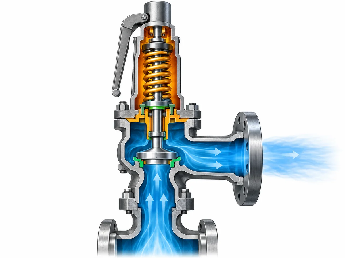
In some corrosive services, an upstream rupture disc can be considered to reduce normal exposure of the pressure relief valve to the process medium. For chlorine service, that can be a useful engineering option—but it is not an automatic requirement and should not be treated as a corrosion shortcut.
Adding a rupture disc changes the protection system. The disc and valve are no longer independent devices that can simply be selected separately and installed in series.
A combination arrangement introduces at least three additional questions.
First, the relieving capacity must be verified for the combination. The standalone capacity of the valve should not automatically be assumed to remain the certified or documented capacity of the assembled rupture-disc/PRV system. The applicable code basis and manufacturer data need to support the combination being used.
Second, the space between the rupture disc and the valve matters. If pressure accumulates in that interspace, it changes the differential pressure acting across the rupture disc and can therefore change its behavior. The arrangement may require venting, pressure indication, monitoring, or another approved method of detecting pressure in that cavity. The exact method depends on the device design, code basis, and project specification.
Third, isolation changes the exposure pattern rather than eliminating the material problem. Under normal operation, the rupture disc may reduce direct contact between the process and the relief valve. During a relief event, after disc opening, or if leakage occurs, the PRV can still be exposed to chlorine. The rupture disc itself, its holder, gaskets, the interspace connection, and the downstream valve components still require appropriate materials.
This creates a real engineering trade-off. Isolation can reduce normal corrosive exposure of the valve, but it adds another pressure-relief device, another material interface, another capacity relationship, and additional inspection and monitoring responsibilities.
Does the defined process and maintenance strategy justify isolating the PRV, and can the disc-and-valve combination be verified as a complete pressure-protection system?
If the answer is yes, the RFQ should identify the proposed combination arrangement and require the manufacturer or engineering authority to confirm the capacity basis, material compatibility, interspace treatment, pressure relationships, installation details, and applicable code requirements.
Design the Discharge Path as Part of the Valve Specification
A chlorine-service relief device cannot be specified responsibly without knowing where the discharge goes.
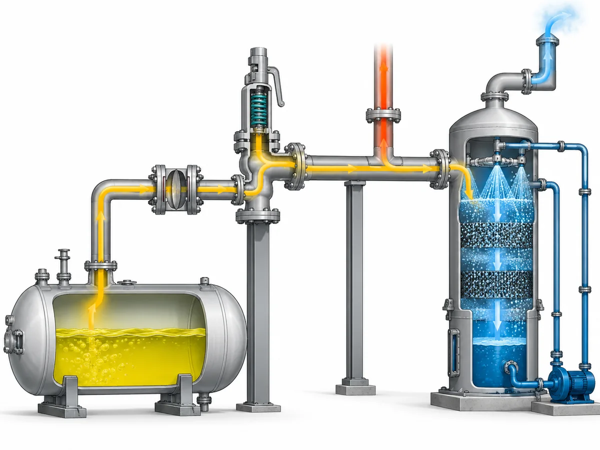
Depending on the facility and governing requirements, relieved chlorine may be routed to a closed receiver, treatment system, scrubber, common relief header, or another approved destination. The correct destination is project- and jurisdiction-specific. This article does not establish that every chlorine relief must discharge to a scrubber, nor does it establish that atmospheric discharge is acceptable for a particular installation.
The engineering point is that the discharge destination can feed back into the valve decision.
Containment can create back pressure
A relief valve discharging into a closed system may see contropressione sovrapposta before it opens and contropressione accumulata as relief flow passes through the outlet piping, header, receiver, or treatment equipment.
Those pressures can affect valve operation, available relieving capacity, stability, and configuration selection. The magnitude and variability of back pressure therefore need to be evaluated against the selected valve’s documented limits. Simply specifying a balanced bellows or pilot-operated design does not make every back-pressure problem disappear; those configurations also have application limits that must be confirmed against manufacturer data and the actual system.
The discharge system should be evaluated as a flow path rather than a destination label. Relevant questions include:
- What pressure already exists at the valve outlet before relief begins?
- How much additional pressure can be generated while the required relief flow passes through the outlet system?
- Does the discharge header serve other relief devices that can operate simultaneously?
- Can liquid collect in the outlet piping?
- Is drainage required?
- Are reaction loads and pipe supports addressed?
- Can downstream vapor, condensate, liquid, or contamination reach the valve under credible operating conditions?
The last question is especially important in chlorine service because moisture can materially change corrosion behavior. That does prescrive mean that every closed relief header will introduce moisture into the valve. It means that if the actual piping arrangement makes downstream exposure or backflow credible, that exposure belongs in the material review.
Containment and material selection are connected
Consider a representative engineering scenario. A process system contains chlorine under a controlled dry condition, while the relief outlet connects to a treatment system. The valve body material might initially be screened against the process-side dry condition. But if the downstream arrangement can subject outlet-side components to a different vapor condition, condensation, liquid accumulation, or back pressure, the engineer has two distinct environments to consider.
That scenario is illustrative, not a recorded project. Its value is the decision logic: material suitability must follow actual exposure paths, and those paths do not necessarily stop at the valve inlet.
The same reasoning applies when a rupture disc is installed upstream. Normal process exposure may be reduced, but relief-event exposure and downstream conditions still need to be considered. The pressure-protection system must work as a whole—from protected equipment, through any isolation device and relief valve, into the disposal or containment system.
Build the Chlorine-Service Verification Package Before RFQ
An RFQ that says only “Need a chlorine-compatible safety valve” leaves the most important engineering questions unanswered.
A supplier cannot safely establish material suitability, configuration, capacity, or documentation requirements from the medium name and connection size alone. Connection size is not relieving capacity, set pressure is not relieving capacity, and a material description is not a sizing basis.
A useful chlorine-service RFQ should provide enough information to evaluate both the service-compatibility problem e la pressure-relief problem.
| Input to provide | Perché cambia la decisione |
|---|---|
| Attrezzatura protetta e scenario di sfioro governativo | Establishes what event the valve must protect against and forms the basis for required relieving load. |
| Chlorine phase and process composition | Affects both sizing and material exposure. |
| Moisture condition or project dry-chlorine specification | Can materially change corrosion and compatibility decisions. |
| Operating pressure and design pressure/MAWP | Establishes the pressure relationship surrounding the set point and normal operating margin. |
| Pressione di taratura | Defines the valve’s opening pressure basis but does not establish capacity. |
| Capacità di sfioro richiesta e base di calcolo | Provides the load the selected device or device combination must be able to relieve. |
| Temperatura operativa e di sfioro | Influences material suitability and the relieving calculation. |
| Contropressione sovrapposta e accumulata | Can affect valve configuration, capacity and stability. |
| Configurazione tubazioni di ingresso e uscita | Identifies pressure-loss, support, discharge and exposure issues that cannot be seen from the valve datasheet alone. |
| Proposed rupture disc or isolation arrangement, if any | Triggers combination-capacity, material, monitoring and installation review. |
| Required body, trim, seat, seal, gasket, spring or bellows materials | Allows component-level compatibility review instead of body-grade-only selection. |
| Discharge destination or containment concept | Establishes the downstream conditions the relief device must operate against. |
| Applicable code, jurisdiction and project specification | Defines the actual acceptance basis; a standard name should not be assumed from the service alone. |
| Required inspection, material and test documentation | Establishes traceability and acceptance deliverables before quotation or order. |
Where an existing valve is being replaced, the old nameplate and connection dimensions can help identify the existing device, but they do not establish a safe direct replacement. Capacity basis, materials, service condition, back pressure, configuration, documentation, and project requirements still need to be checked.
The same caution applies to catalog data. A manufacturer’s general material matrix can identify available construction options, but it should not be converted automatically into a chlorine-suitability statement. Exact suitability belongs to the selected product configuration and the defined service condition.
Before requesting a final valve selection, assemble the chlorine condition, relief scenario, required capacity, pressure and temperature basis, back pressure, material requirements, any rupture-disc arrangement, discharge destination, and documentation requirements. With those inputs available, an engineering review can determine which product configuration and material set should be evaluated against the actual project.
Ask a Safety Valve Engineer: send the operating and relieving conditions, required relieving capacity or calculation basis, chlorine condition, discharge arrangement, back pressure, proposed materials, applicable project requirements, and any existing valve or rupture-disc data. The review should confirm suitability and capacity from the selected product data rather than assuming them from a generic chlorine-service description.