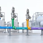
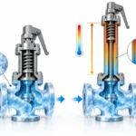
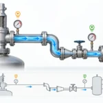
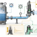
Comprendere la forza di reazione allo scarico della valvola di sicurezza, lo scarico libero e convogliato, i percorsi di carico sulle tubazioni, i carichi su supporti e bocchelli e i dati necessari per la verifica delle sollecitazioni.

La forza di reazione allo scarico di una valvola di sicurezza è il carico meccanico indotto dal flusso durante un evento di sfioro. È un dato importante per la progettazione della tubazione di scarico, ma non è automaticamente il carico su un supporto di tubazione, sulla connessione della valvola o sul bocchello di un'apparecchiatura collegata.
La sequenza ingegneristica è più ampia:
Definire la condizione di sfioro → identificare il confine di scarico → calcolare la forza di reazione applicabile → tracciare il percorso effettivo del carico sulla tubazione → verificare i supporti, i carichi sui bocchelli e le eventuali verifiche di sollecitazione o dinamiche richieste.
Un punto di criticità comune non è il calcolo della forza di reazione in sé, ma ciò che avviene dopo: la forza viene calcolata per un confine e poi applicata alla tubazione installata come se fosse già il carico finale sui supporti o sui bocchelli.
Che cosa rappresenta realmente la forza di reazione allo scarico di una valvola di sicurezza?
Quando il fluido in scarico esce da una valvola di sicurezza o dal suo sistema di scarico,
le variazioni di quantità di moto del fluido e di pressione al confine di scarico possono
generare una reazione meccanica. Nello scarico libero di fluidi comprimibili, i metodi
ingegneristici comunemente utilizzati tengono conto sia degli effetti della quantità di moto sia della spinta di pressione.
Questa trattazione è documentata in
Emerson Pressure Relief Valve Engineering Handbook.
Il confine importante è ciò che quel calcolo indica. Un
forza di reazione allo scarico è un carico di ingresso associato
al flusso di scarico. Di per sé, non stabilisce:
- la reazione su un particolare supporto della tubazione;
- la forza o il momento trasmesso al collegamento della valvola;
- il carico ammissibile di quel collegamento della valvola;
- il carico su un recipiente, un collettore o un bocchello di apparecchiatura; oppure
- lo stato tensionale combinato della tubazione di scarico.
Tali grandezze dipendono dalla geometria della tubazione installata e dai suoi
vincoli. Un'affermazione del tipo “la valvola produce una forza X, quindi il
supporto più vicino deve resistere a X” è pertanto incompleta. La reazione
calcolata deve essere inserita nel modello meccanico della tubazione di
scarico reale prima che i carichi su supporti e bocchelli possano essere valutati.
Per requisiti più ampi su ingresso, drenaggio, orientamento e instradamento dello scarico
consultare la
Guida all'installazione delle valvole di sicurezza
.
Questa pagina resta incentrata sulla forza di reazione e sulla sua interpretazione
meccanica.
Quali dati di ingresso determinano la forza di reazione allo scarico?
Non partire dalla dimensione nominale dell'uscita della valvola. Parti dalla
condizione di sfioro e dalle condizioni effettive di scarico.
Stati del fluido diversi richiedono trattamenti ingegneristici diversi.
L'Emerson Pressure Relief Valve Engineering Handbook presenta approcci separati
per gas o vapore, vapore acqueo, liquido non flash e flusso bifase
anziché un'unica equazione universale della forza di reazione.
| Ingresso | Perché è importante |
|---|---|
| Portata massica di scarico | Determina la quantità di moto associata allo scarico. |
| Stato del fluido e della fase |
Determina quale metodo di calcolo e quali ipotesi sono applicabili. |
| Temperatura di scarico o di sfioro | Interviene nel trattamento termodinamico applicabile. |
| Proprietà rilevanti del fluido |
I metodi per gas/vapore, liquidi e bifase richiedono proprietà diverse. |
| Area di uscita o di scarico |
Definisce parte del contorno di scarico utilizzato nel calcolo della forza calcolo. |
| Pressione di uscita | La spinta di pressione può contribuire alla reazione. |
| Pressione ambiente o a valle | Definisce il confine di pressione rispetto al quale avviene lo scarico. |
| Scarico aperto o collegato |
Determina se un approccio a scarico in atmosfera è applicabili. |
| Geometria effettiva a valle |
Diventa necessario quando si converte la forza locale in un problema di carico sulle tubazioni. |
L'implicazione pratica è semplice: due valvole con lo stesso
attacco di uscita possono avere carichi di reazione diversi se la portata di scarico,
lo stato del fluido, il confine di pressione o la configurazione di scarico differiscono.
Le ipotesi di fase richiedono particolare attenzione. Un metodo sviluppato per gas o
vapore non deve essere applicato allo scarico di liquido solo perché le
la dimensione della connessione è la stessa. Analogamente, un metodo per liquidi che presuppone
un servizio non flashing non è automaticamente valido per un liquido flashing,
e un modello omogeneo bifase rimane subordinato alle sue assunzioni
dichiarate.
Se la portata di scarico richiesta non è ancora stata determinata,
completare prima tale attività. Il
Guida al dimensionamento delle valvole di sicurezza e alla capacità di scarico certificata
è responsabile di tale compito; questo articolo considera la portata di scarico come un dato di input per la
verifica meccanica.
Perché i sistemi di scarico aperti e chiusi richiedono un trattamento diverso
Prima di scegliere un calcolo della forza di reazione, determinare
dove la valvola di sicurezza scarica.
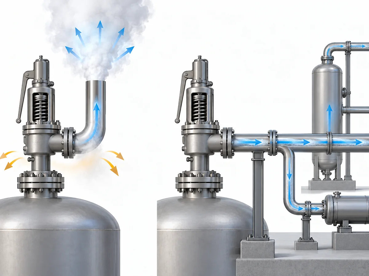
Uno scarico aperto rilascia il fluido attraverso una terminazione definita verso
atmosfera. Uno scarico chiuso rimane collegato a tubazioni a valle,
a un collettore o a un altro sistema di smaltimento. Questa differenza modifica il
confine di calcolo.
API 520 Parte II
è la famiglia di riferimento API pertinente per l'installazione, mentre le linee guida
di progettazione del produttore, come il capitolo sull'installazione del
LESER Engineering Handbook,
illustrano la distinzione tra sistema aperto e chiuso e i relativi limiti.
| Scarico aperto / in atmosfera | Scarico chiuso / collegato |
|---|---|
| Di norma è possibile identificare un confine di scarico terminale. | Le tubazioni a valle rimangono parte del sistema pressione/portata. |
| I metodi di reazione per scarico aperto possono essere applicabili. |
Una formula di scarico in atmosfera non dovrebbe essere trasferita automaticamente. |
|
Gli effetti di quantità di moto e pressione possono essere valutati alla terminazione. |
Pressione, velocità, geometria e comportamento transitorio possono interagire attraverso il sistema collegato. |
| Spesso è possibile definire un vettore di reazione locale. |
Le forze a livello di sistema possono dipendere da dilatazioni, curve, vincoli, e condizioni a valle. |
In condizioni di flusso stazionario consolidato, le forze all'interno di alcuni sistemi
chiusi possono bilanciarsi parzialmente. Ciò non prescrive justify
the blanket conclusion that a closed relief system has no mechanically
significant reaction load.
Changes in section, direction, downstream pressure, and transient flow
can still matter. The defensible rule is:
Define the discharge boundary before selecting the calculation method.
Back pressure belongs nearby in the engineering logic, but it is not
synonymous with reaction force. Back pressure describes the outlet
pressure condition affecting the relief system; reaction/support
analysis asks how the resulting fluid and pressure behavior loads the
mechanical system.
For detailed superimposed and built-up back-pressure discussion, use
the dedicated
Contropressione e soffietto
guida.
When Is a Steady Reaction Force Not Enough?
A steady-state reaction calculation answers a specific question:
what reaction is associated with the established relieving flow?
It does not necessarily answer:
what is the complete mechanical load history while the valve opens
and the discharge system responds?
During opening, pressure and flow change with time. A published study
on safety-valve blowdown by Muschelknautz and Wellenhofer reported
short-duration reaction-force peaks during the opening process in the
configurations they studied. That supports treating steady and transient
loading as related but distinct engineering questions rather than
assuming that one steady value describes the entire event.
Vedi la
Wiley study on flow reaction forces during safety-valve blowdown.
A transient or dynamic review becomes more relevant when, for example:
-
the valve opening event is rapid compared with the response of the
piping system; -
pressure waves or unsteady flow in connected discharge piping may
affect the mechanical response; - the system is sensitive to short-duration loads; or
- the governing project/code basis requires a dynamic treatment.
This is a screening boundary, not a claim that every safety valve needs
a time-history analysis. The opposite shortcut is also unsafe: a single
steady-state force should not automatically be treated as the complete
event load.
The method must follow the piping code, edition, and project basis that
actually govern the installation.
ASME B31.1,
for example, is a Power Piping code and should not be treated as a
universal substitute for a different governing piping code. This
article therefore does not publish a universal dynamic load multiplier.
How Does Outlet Piping Geometry Change the Load Path?
Once the reaction force has been calculated, the next engineering
question is:
where does that load go in the installed piping?
Geometry controls much of that answer. Emerson Birkett technical
guidance notes that an unsupported discharge pipe can act as a lever,
so the mechanical load applied to the valve depends on both the
discharge reaction and the piping geometry. That is why pipe length,
direction changes, and restraint locations matter after the local
reaction force has been established.
Vedi la
Emerson Birkett safety-relief-valve technical data.
Direction changes add another layer. At an elbow, the fluid momentum
changes direction, so the discharge system must be considered as a set
of force vectors, moment arms, supports, and boundary conditions rather
than as one scalar force traveling unchanged down the pipe.
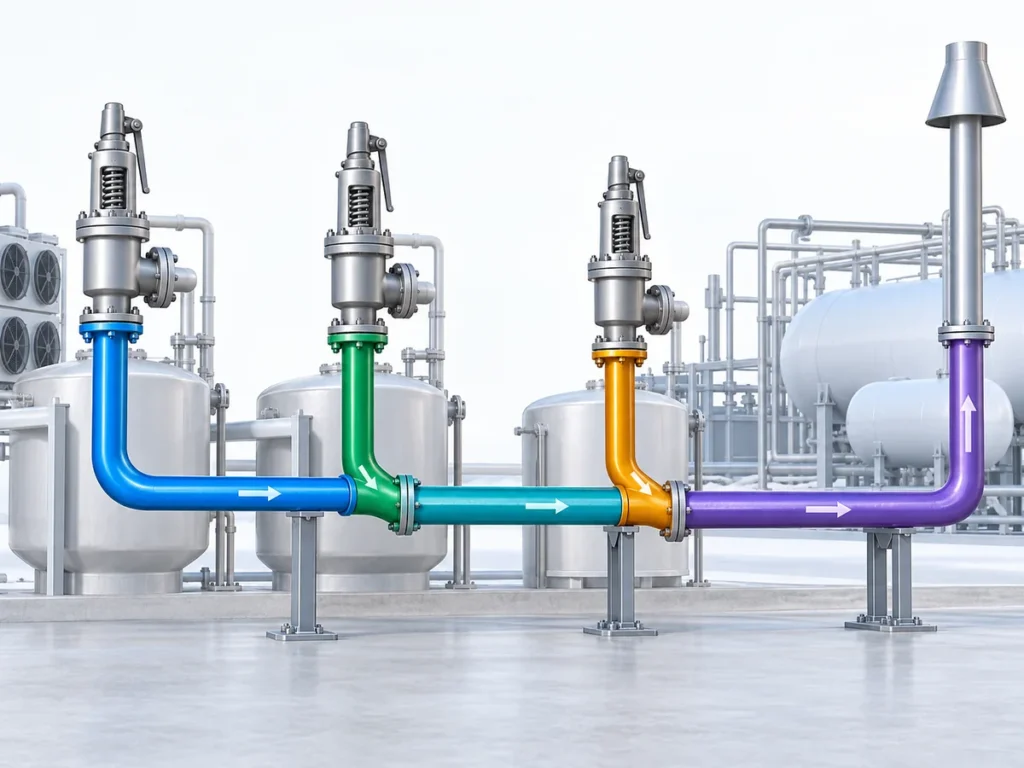
Relieving flow → reaction vector → piping geometry → direction
changes and moment arms → restraints → valve/support/equipment loads.
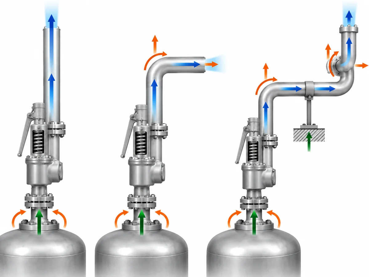
An offset, elbow, vent stack, silencer, reducer, or connection into
downstream piping can alter the load path. The exact consequence depends
on the actual geometry and restraints.
Supports also do more than carry weight. A guide, anchor, line stop, or
other restraint changes the mechanical boundary condition of the piping
system. Do not turn that into a fixed support-spacing rule: the suitable
arrangement depends on the actual piping geometry, restraint model, and
allowable loads.
The relief reaction is also only one load case. Depending on the
project, the installed system may have to accommodate dead weight,
thermal movement, pressure-related loading, discharge reaction, and
applicable transient or occasional loads.
A layout that works for weight does not automatically work for relief
loading. Conversely, adding excessive restraint simply to resist thrust
can create other mechanical consequences when the piping expands
thermally.
Why Reaction Force Is Not the Same as the Final Support or Nozzle Load
The reaction-force calculation and the final mechanical acceptance
check are separate engineering milestones.
| Quantità | Cosa rappresenta | What controls it |
|---|---|---|
| Discharge reaction force | Flow-induced load associated with the relief event. |
Relief flow, phase/state, pressure boundary, outlet condition, and applicable calculation method. |
| Load at the valve connection | Force and moment transmitted between valve and connected piping. |
Reaction force, geometry, moment arms, restraints, and other piping loads. |
| Support reaction | Load carried by a particular support or restraint. |
Complete piping geometry, stiffness, restraints, and applicable load cases. |
| Equipment/nozzle load |
Load transferred to a vessel, header, or other equipment connection. |
Mechanical response of the connected system. |
| Pipe-stress result | Combined piping response. |
Pressure, weight, thermal, relief-event, and other project-defined load cases. |
The difference becomes clearer with a simple thought experiment.
Assume two systems have the same calculated discharge reaction. One has
a short, well-defined outlet route with a nearby engineered restraint.
The other has a longer offset before the piping is supported.
The flow reaction can be the same while the bending moment and loads
transmitted into the valve or supports are different.
Ecco perché
allowable loads cannot be inferred from the reaction-force equation
.
A valve-nozzle allowable, vessel-nozzle allowable, support capacity, or
equipment allowable must come from the documentation applicable to the
actual valve, equipment, structure, or project.
Values from another manufacturer’s valve or another installation are
not substitutes. No model-specific ZOBAI allowable outlet/nozzle load
is established by this article, so none should be inferred from the
generic engineering discussion.
What Should Be Verified Before the Outlet Piping Support Arrangement Is Accepted?
The ten checks below are a practical engineering review
framework for this article. They are not presented as a
universal API or ASME mandated sequence. The governing project code,
equipment documentation, and piping/stress design basis remain the
authority for an actual installation.
-
Establish the relief duty.
Confirm the governing relief case and required relieving-flow basis.
If the required flow is still unknown, the mechanical reaction
calculation is premature. -
Establish the fluid and phase state.
Identify whether the relieving stream is gas/vapor, steam,
non-flashing liquid, or a case requiring two-phase treatment. -
Define the discharge boundary.
Confirm whether the valve discharges openly to atmosphere or into
connected downstream piping. For a connected system, also establish
the relevant downstream pressure and routing information. -
Use a reaction-force method that matches that boundary.
Keep the result tied to its calculation boundary instead of
immediately treating it as the load at a support. -
Map the real outlet geometry.
Record the valve outlet orientation, straight pipe lengths, elbows,
offsets, reducers or expansions where relevant, silencers or other
inline items where present, and connection to any vent, header, or
disposal system. -
Define the restraints.
Identify the actual supports, guides, anchors, line stops, structural
attachments, and other boundary conditions relevant to the piping
analysis. -
Include the other applicable load cases.
Determine which additional loads have to be considered under the
project’s design basis, including weight, thermal movement, pressure
effects, and any applicable occasional or dynamic case. -
Obtain the real allowable loads.
Use valve-, equipment-, support-, and project-specific documentation.
If a decision-critical nozzle or structural allowable is missing, the
mechanical acceptance is not complete. -
Decide whether the steady calculation is sufficient.
Confirm whether the installed configuration and governing design
basis require any additional transient or dynamic assessment. -
Close the piping/stress review.
For an actual project, the relief duty, calculation boundary, piping
layout, restraints, applicable load cases, and relevant allowable
loads need to be resolved before the mechanical acceptance can be
closed.
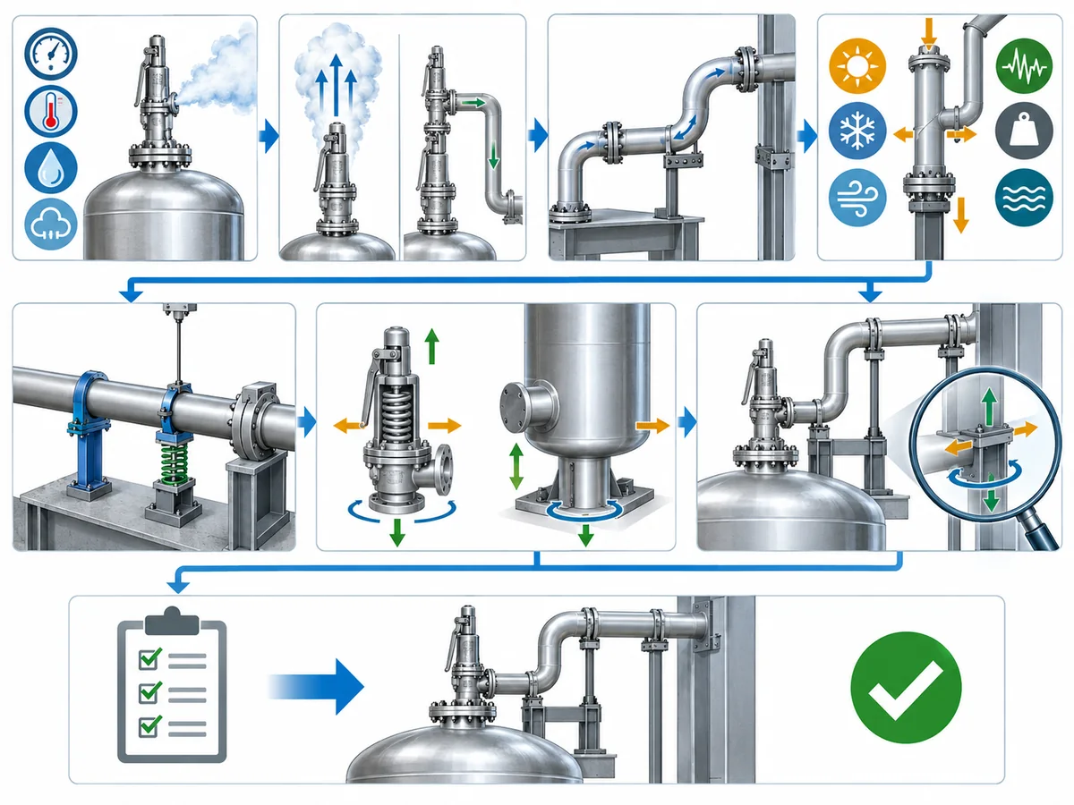
The useful project handoff is therefore not simply
“reaction force = ___.” It is:
relief duty + fluid state + discharge boundary + reaction-force basis
+ actual geometry + restraint model + applicable allowable loads +
dynamic-review status.
That package allows process/relief and piping/stress disciplines to work
from the same design basis.
Preparing a safety valve RFQ or outlet-system review?
Send the known relief case, fluid and phase, required relieving rate,
pressure and temperature conditions, back pressure or discharge route,
and applicable project requirements through
Chiedi a un ingegnere di valvole di sicurezza
.
ZOBAI can use confirmed valve/application inputs for the valve review;
final piping-support and stress acceptance remains dependent on the
installed project system.
A safety-valve reaction-force calculation is neither “just a formula” nor the final support design. It is the bridge between the relief calculation and the mechanical review of the installed discharge system.
Calculate the correct reaction for the correct discharge case, then verify how the actual piping carries it.