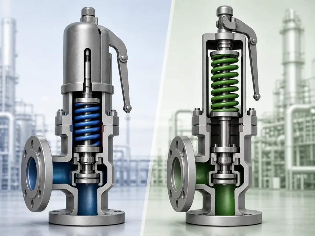
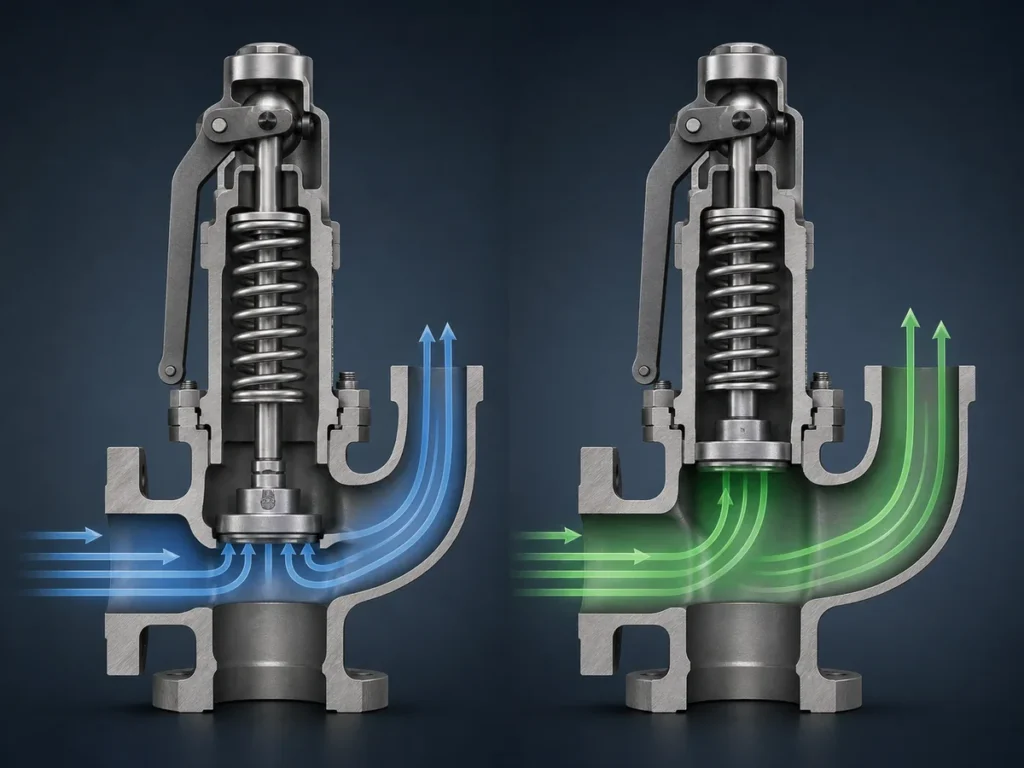
A trapped-liquid LPG relief review starts with the piping boundary, not with a valve model. First determine whether liquid can be isolated, identify the exact section enclosed by that isolation, establish a credible condition that can warm the trapped liquid, and define where relief flow is intended to go. Device suitability and the installed relief …

A trapped-liquid LPG relief review starts with the piping boundary, not with a valve model. First determine whether liquid can be isolated, identify the exact section enclosed by that isolation, establish a credible condition that can warm the trapped liquid, and define where relief flow is intended to go. Device suitability and the installed relief path can only be evaluated against that system basis.
In questo contesto, sfioro termico descrive la funzione di protezione associata al riscaldamento di un volume di liquido intrappolato. Valvola di sfioro idrostatica is also established terminology in LP-Gas regulatory and standards contexts. Neither term should be reduced to a generic LPG safety-valve label: the actual liquid-service duty still has to be confirmed.
The scope here is blocked-in liquid LPG piping. Storage-vessel relief, vessel fire scenarios, vacuum protection and general pressure-relief sizing use different protected boundaries or design bases and remain separate engineering subjects.
How Does a Liquid LPG Line Become Blocked In?
Confini di isolamento che possono creare una sezione di liquido intrappolato
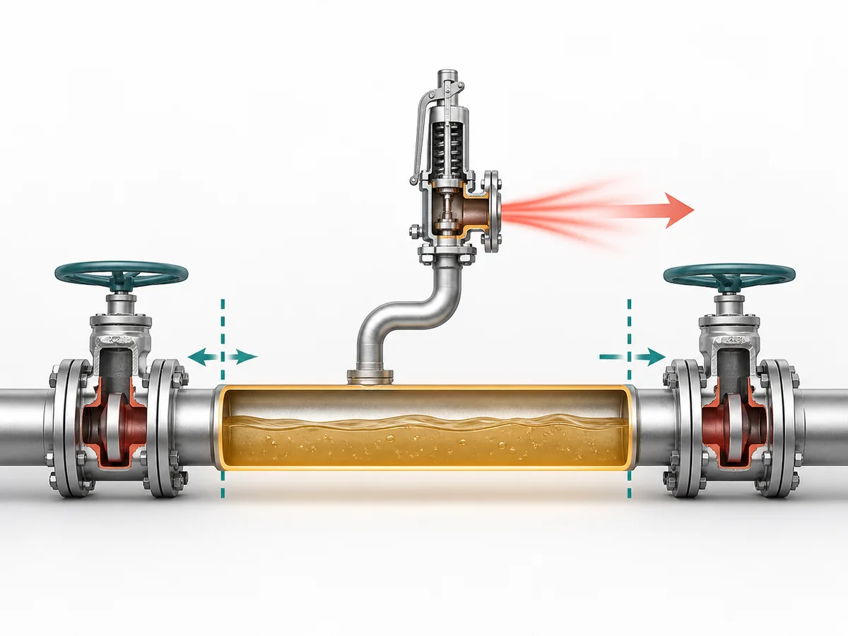
Una sezione intrappolata candidata esiste quando una parte della tubazione piena di liquido può essere racchiusa da confini di isolamento efficaci. La chiusura delle valvole o di altri punti di isolamento efficaci su entrambi i lati può rimuovere il percorso normale per il liquido di muoversi nel sistema circostante.
La guida sui processi di tubazioni dell'Health and Safety Executive (HSE) del Regno Unito riconosce esplicitamente il liquido intrappolato tra confini di isolamento chiusi. I requisiti LPG dell'Occupational Safety and Health Administration (OSHA) degli Stati Uniti affrontano separatamente il GPL liquido intrappolato tra confini di intercettazione nel loro ambito applicabile. Il compito pratico è quindi individuare l'effettiva sezione di liquido racchiusa piuttosto che trattare l'intera installazione GPL come un unico volume protetto.
La presenza di due punti di isolamento apparenti non è, di per sé, la conclusione. L'ingegneria deve ancora stabilire che la sezione contenga liquido nello stato rilevante e che tali confini possano effettivamente isolarla.
Stati della valvola in esercizio normale rispetto alla manutenzione
La configurazione di flusso normale potrebbe non rivelare ogni condizione di blocco. L'avviamento, lo spegnimento, la manutenzione o un altro stato operativo legittimo possono modificare quali confini sono aperti e quali sezioni diventano isolate.
Esaminare lo stato della valvola insieme alla condizione del liquido. Una domanda più utile di “Questa valvola è normalmente aperta?” è:
Uno stato operativo o di manutenzione rilevante può lasciare liquido confinato all'interno di questa sezione?
Ciò impedisce che la revisione dello sfioro si basi solo sul quadro del flusso normale, trascurando un diverso stato di isolamento che modifica il confine protetto.
Definire la sezione intrappolata prima di discutere il dispositivo di sfioro
Tracciare il confine protetto prima di valutare il dispositivo di sfioro. Il confine deve identificare la sezione piena di liquido, i punti di isolamento effettivi e la connessione attraverso cui il percorso di sfioro previsto rimarrebbe disponibile.
- Confermare la sezione che può trattenere liquido.
- Confermare i punti di isolamento che possono racchiuderla.
- Confermare lo stato operativo o di manutenzione in cui si verifica tale racchiusura.
- Confermare se la connessione di sfioro prevista rimane collegata a quella sezione nello stesso stato.
Una dichiarazione generale secondo cui il sistema LPG più ampio contiene già apparecchiature di scarico della pressione non risponde a queste domande per un segmento separato e bloccato.
Perché il riscaldamento di un segmento di liquido LPG intrappolato può creare un problema di sovrappressione?
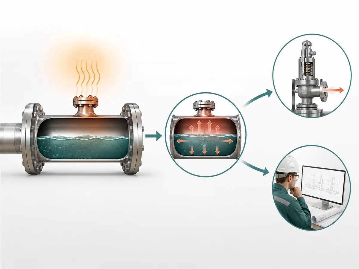
Il meccanismo di espansione termica
Quando la sezione rimane idraulicamente collegata al processo circostante, il liquido può muoversi al variare delle condizioni del sistema. Una volta che il liquido è confinato tra confini effettivi, questa libertà è limitata.
Le linee guida HSE per le tubazioni di processo identificano la variazione di temperatura e l'espansione termica del liquido intrappolato come una potenziale preoccupazione per la perdita di contenimento. Il Petroleum and Natural Gas Regulatory Board (PNGRB) dell'India affronta allo stesso modo la protezione dall'espansione termica per il liquido LPG intrappolato nel suo ambito normativo.
La decisione ingegneristica immediata non è quindi un calcolo della capacità. È se la combinazione di confinamento del liquido e una condizione di riscaldamento credibile crea un dovere di sfioro termico o idrostatico che richiede ulteriore ingegneria.
Perché questo dovere è diverso dallo sfioro per incendio del serbatoio
Il sistema protetto definisce il problema. Per una linea bloccata, il punto di partenza è un segmento di tubazione con liquido confinato e una condizione di riscaldamento che interessa quel segmento. Uno scenario di emergenza o incendio di un serbatoio di stoccaggio parte da un sistema protetto diverso e da una base di sfioro diversa.
Il fatto che entrambi i problemi possano coinvolgere apparecchiature di scarico della pressione non rende l'uno un sostituto dell'altro. Un sistema di sfioro del serbatoio non dovrebbe essere considerato in grado di proteggere una linea di liquido che può essere isolata al di fuori del confine effettivo di sfioro del serbatoio.
Cosa significa “riscaldamento credibile” in questa fase
Una condizione di riscaldamento credibile è una condizione reale di progetto in grado di aumentare la temperatura del liquido mentre la sezione identificata rimane isolata. Deve derivare dalla base di installazione e di esercizio, non da un esempio generico di sfioro termico.
HSE guidance identifies external heat, temperature gradients and temperature cycling as conditions that may deserve review where they apply. OSHA also recognizes abnormal external heat exposure in defined LPG installation contexts. These sources support the need to examine real warming mechanisms; they do not establish one universal list for every LPG line.
La sequenza utile è pertanto la seguente: prima verificare che il segmento possa essere isolato, quindi individuare la condizione che può riscaldarlo mentre è isolato. Se la base di riscaldamento non è nota, mantenerla come dato di progetto non risolto anziché sostituirla silenziosamente con uno scenario ipotizzato.
Come si definisce il segmento protetto e la condizione di riscaldamento credibile?
Definire i confini fisici del segmento protetto
Iniziare dalla linea o dalla sezione dell'apparecchiatura contenente liquido e tracciare in entrambe le direzioni finché non si comprendono i confini di isolamento effettivi. Quindi individuare il collegamento di sfioro previsto rispetto a tali confini.
La revisione dei confini dovrebbe rispondere:
- Quale sezione fisica può trattenere liquido?
- Quali punti di isolamento possono racchiudere tale sezione?
- In quale stato rilevante della valvola avviene la chiusura?
- Il collegamento di sfioro previsto rimane sul lato protetto di tali confini?
Un P&ID è un punto di partenza, non un sostituto della filosofia operativa e di manutenzione. Laddove lo stato del disegno e la pratica effettiva di isolamento non siano ancora riconciliati, il confine protetto rimane irrisolto.
Verifica quali stati della valvola possono effettivamente isolarla
Review the states that can change the boundary of this segment rather than expanding the task into a facility-wide valve inventory. A line may remain connected during normal operation but become enclosed during maintenance. Conversely, isolation points shown on a drawing do not prove that liquid is trapped in every state.
Ask whether this actual valve state can confine liquid between effective boundaries while the section is exposed to the warming condition under review.
A “yes” identifies a scenario requiring thermal-relief review. An unknown valve state, liquid condition or boundary remains an information gap. It should not be converted into either a positive or negative selection conclusion.
Identify the Warming Condition Engineering Must Evaluate
Pair the protected boundary with the project condition that can warm the liquid while that same boundary exists. This avoids evaluating a warming condition that occurs only when the line is open, or an isolation state that is never exposed to the proposed warming mechanism.
The decision basis can be expressed qualitatively as:
protected segment + relevant isolation state + credible warming condition.
This is a boundary-definition framework, not a sizing formula. Detailed relief calculations belong after the scenario and its project inputs have been established.
How Should the Thermal-Relief Discharge Path Be Defined?
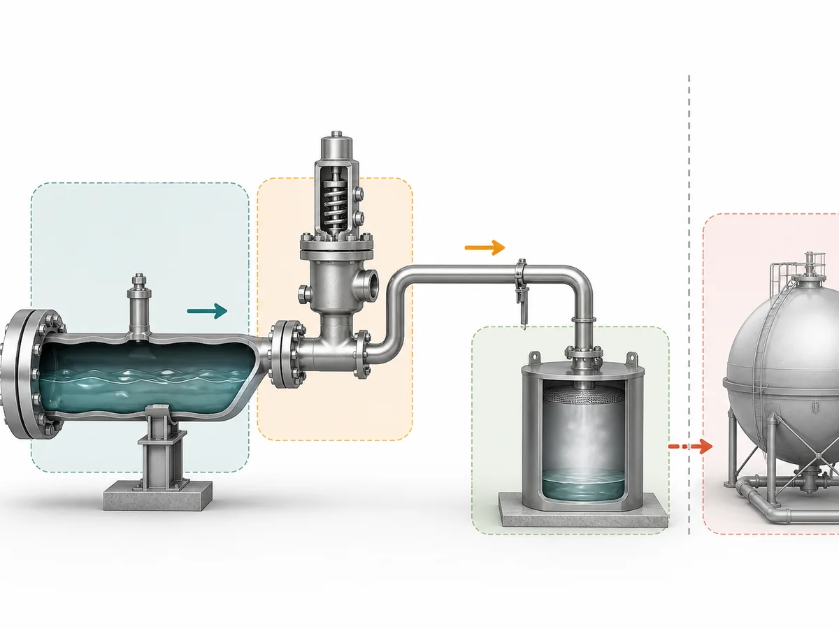
Identify the Intended Discharge Destination
A relief device is not fully defined by its connection to the trapped segment. The engineering basis also needs to state where relieved LPG is intended to go.
OSHA’s LPG requirements provide a scope-specific example in which hydrostatic relief from specified liquid piping is directed to a safe atmosphere. That requirement should not be generalized beyond its applicable jurisdiction and system scope. Where another pressure-containing or product-retaining system is proposed as the receiving destination, the connected-system conditions must be carried into the appropriate engineering review rather than treated as automatically acceptable.
The practical conclusion is that the project must establish the intended destination under its applicable requirements and receiving-system conditions before treating the relief path as resolved.
The relief path remains unresolved until the receiving destination and its applicable project boundary are known.
Identify Downstream Pressure or Back-Pressure Conditions
When the outlet enters another pressure-containing or product-retaining system, that receiving system can impose conditions at the relief-device outlet. Those conditions are therefore part of the engineering input to later device and installation review.
The project package should identify the receiving system and the relevant downstream pressure condition rather than describing the outlet only as “closed” or “connected.” Detailed acceptability of the connected network remains a separate downstream-system analysis.
American Petroleum Institute (API) pressure-relief installation guidance treats installed relief arrangements as an engineering-analysis subject. This page therefore does not establish an allowable back pressure, size a return path, or design a disposal, recovery or shared relief network; those decisions remain with the appropriate downstream engineering owner.
Route Closed-System Questions to the Appropriate Downstream Analysis
A product-retaining or other closed receiving system should not be interpreted as acceptable merely because a physical connection is available. The relevant question for this article is whether the destination and downstream condition are sufficiently defined for the next engineering decision.
- If the destination is not established, retain it as an RFQ or project-data gap.
- If the outlet connects to another pressure-containing system, identify the downstream condition for the responsible system analysis.
- If acceptability depends on connected-network hydraulics, route that question to the downstream relief-system owner instead of solving it inside this page.
Phase change remains conditional. If project-specific fluid and downstream conditions make a phase transition material to the relief analysis, it should be addressed in the separate sizing or downstream-system review. It is not treated here as a universal selection gate for every trapped-liquid LPG line.
How Do You Verify Liquid-Service Suitability and Keep the Relief Path Available?
Confirm That the Proposed Device Is Intended for the Required Liquid-Service Duty
Broad LPG service wording is not enough to establish suitability for a blocked-in liquid thermal or hydrostatic relief duty.
UL Standards & Engagement recognizes hydrostatic relief valves as an LP-Gas relief-device category, while PNGRB separately addresses suitable thermal pressure relief where liquid can be trapped. The procurement implication is limited but important: suitability for this duty should be supported directly rather than inferred from a generic LPG valve-family description.
Device review therefore starts with the system basis already defined in the earlier sections: the protected segment, liquid condition, warming scenario, intended discharge destination and relevant downstream condition. Product-specific suitability can then be confirmed against that basis by the responsible supplier or engineering reviewer.
Check Whether Isolation Can Disable the Relief Path
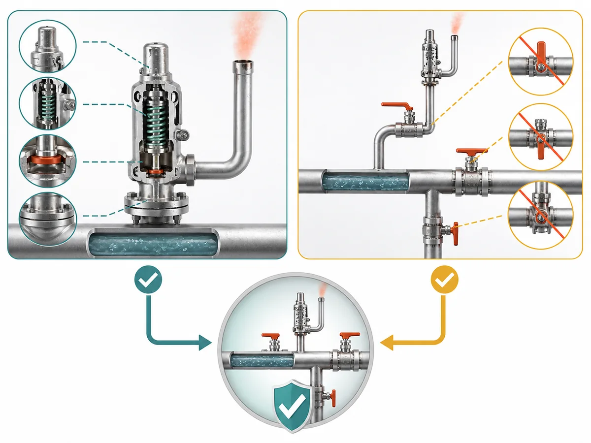
Device suitability does not protect the trapped segment if the installed arrangement can disconnect that device from the segment in the state when relief is needed.
Within the directly frozen U.S. OSHA LP-Gas scope, arrangements that can isolate a relief device from protected equipment or piping are restricted unless the required relief path is preserved. HSE process-pipework guidance separately identifies isolation-valve location as an important consideration where trapped-liquid thermal expansion is possible.
For each relevant operating or maintenance state, check whether an effective isolation boundary can separate the intended relief connection from the trapped liquid segment.
If it can, the arrangement is not resolved by this article. Its acceptability has to be established under the applicable project and jurisdictional requirements. The exact acceptable isolation arrangement is deliberately not generalized here.
Keep Installation Review Separate From Generic Valve Selection
Two confirmations are required, and one cannot substitute for the other:
- Duty suitability: evidence for the proposed device supports the intended trapped-liquid LPG thermal or hydrostatic service.
- Path availability: the installed isolation arrangement keeps the intended relief path connected to the protected segment in the relevant state, subject to applicable project requirements.
Keeping these questions separate prevents a common reasoning error: choosing a nominally relevant device and then treating installation availability as automatically proven.
What Information Should Go Into an LPG Thermal-Relief RFQ?
The RFQ should allow each responsible party to see what is already established, what still needs confirmation and who owns the unresolved decision. It should not force the supplier to reconstruct the protected boundary from a generic valve description.
| Input group | Informazioni di progetto | Primary confirmation responsibility | Decision supported |
|---|---|---|---|
| Protected segment | P&ID or line identification, liquid-containing section and effective isolation boundaries. | Project or piping engineering establishes the system boundary. | Defines exactly what section requires review. |
| Isolation states | Relevant normal, operating and maintenance valve states. | Project or operating basis establishes when the section can become enclosed; installation review checks relief-path availability. | Connects the protected boundary to the state in which relief may be required. |
| Fluid and operating basis | Available LPG fluid definition, confirmation of liquid service, and the project’s pressure and temperature basis. | The project supplies the service basis; the device reviewer evaluates suitability against it. | Prevents device suitability from being inferred from a generic LPG label. |
| Credible warming | The actual project condition capable of warming the liquid while the segment is isolated. | The project establishes the credible scenario. | Defines the thermal-expansion duty that later engineering must evaluate. |
| Relief destination and downstream condition | Proposed relief location, intended receiving destination and relevant downstream pressure condition. | The project identifies the destination; the responsible downstream-system owner resolves connected-system effects where required. | Separates valve-duty definition from closed-system or downstream-network analysis. |
| Compatibility and project requirements | Applicable fluid-compatibility requirements, project requirements, jurisdictional basis, isolation philosophy and required documentation. | The project supplies its requirements; the supplier or engineering reviewer confirms the device-specific evidence. | Establishes what must be demonstrated rather than assumed during final selection. |
Protected-Segment and Operating Information
Project or piping engineering should provide enough information to reconstruct the protected boundary: the relevant line or P&ID reference, the section that can contain liquid, the effective isolation points and the valve states that can enclose it.
Fluid and operating information belongs with that boundary. These inputs establish the service basis for later engineering; they do not themselves prove a device result.
Warming, Discharge and Downstream Information
The project should state the credible condition that can warm the trapped liquid, the intended relief-device location and the proposed receiving destination.
Where the outlet enters another system, the relevant downstream condition should also be supplied or explicitly assigned for separate analysis. An unknown warming basis, destination or downstream condition should remain visible as an unresolved field rather than being replaced by a generic assumption.
Compatibility, Project and Isolation Requirements
The RFQ should distinguish requirements supplied by the project from evidence that the device reviewer must confirm. Project inputs include the applicable service, compatibility requirements, jurisdictional or project basis, isolation philosophy and documentation expectations.
The responsible supplier or engineering reviewer can then assess device-specific suitability against those inputs. This preserves the difference between stating the service requirement and claiming that a particular product satisfies it.
What the Supplier Must Confirm Rather Than the Buyer Assume
The buyer or project team owns the system basis: what can become trapped, when the boundary exists, what can warm the liquid, where relief is intended to go and which project requirements govern the review.
The supplier or engineering reviewer owns the device-specific confirmation needed to show that a proposed device is suitable for that submitted duty. When the outlet joins another pressure-containing system, the responsible downstream-system owner retains the connected-system analysis.
Do not close the RFQ by assuming that:
- a generic LPG valve description proves liquid thermal or hydrostatic relief suitability;
- a proposed discharge destination is acceptable before its project and receiving-system boundary is established;
- the relief connection remains available through every relevant isolation state without checking the installed path;
- missing boundary, warming, service or downstream information can be replaced with generic data.
A technically useful RFQ therefore does more than request a valve. It gives each reviewer enough evidence to identify the blocked-in duty, separate confirmed inputs from unresolved ones, and assign the remaining engineering decisions to the correct owner before final selection.