A trapped-liquid LPG relief review starts with the piping boundary, not with a valve model. First determine whether liquid can be isolated, identify the exact section enclosed by that isolation, establish a credible condition that can warm the trapped liquid, and define where relief flow is intended to go. Device suitability and the installed relief …

A trapped-liquid LPG relief review starts with the piping boundary, not with a valve model. First determine whether liquid can be isolated, identify the exact section enclosed by that isolation, establish a credible condition that can warm the trapped liquid, and define where relief flow is intended to go. Device suitability and the installed relief path can only be evaluated against that system basis.
En este contexto, alivio térmico describe la función de protección asociada al calentamiento de un volumen de líquido atrapado. Válvula de alivio hidrostático is also established terminology in LP-Gas regulatory and standards contexts. Neither term should be reduced to a generic LPG safety-valve label: the actual liquid-service duty still has to be confirmed.
The scope here is blocked-in liquid LPG piping. Storage-vessel relief, vessel fire scenarios, vacuum protection and general pressure-relief sizing use different protected boundaries or design bases and remain separate engineering subjects.
How Does a Liquid LPG Line Become Blocked In?
Límites de aislamiento que pueden crear una sección de líquido atrapado
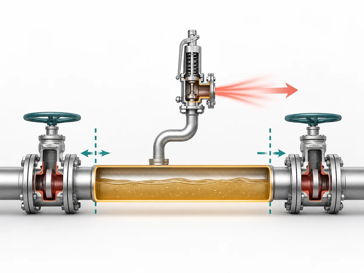
Existe una sección atrapada candidata cuando una parte de la tubería llena de líquido puede quedar encerrada por límites de aislamiento efectivos. El cierre de válvulas u otros puntos de aislamiento efectivos en ambos lados puede eliminar la vía normal para que el líquido se mueva hacia el sistema circundante.
La guía de tuberías de proceso del Health and Safety Executive (HSE) del Reino Unido reconoce explícitamente el líquido atrapado entre límites de aislamiento cerrados. Los requisitos de LPG de la Administración de Seguridad y Salud Ocupacional (OSHA) de EE. UU. abordan por separado el LPG líquido atrapado entre límites de cierre dentro de su alcance aplicable. Por lo tanto, la tarea práctica es localizar la sección de líquido encerrada real en lugar de tratar toda la instalación de LPG como un volumen protegido.
La presencia de dos puntos de aislamiento aparentes no es, por sí misma, la conclusión. La ingeniería aún debe establecer que la sección contiene líquido en el estado relevante y que esos límites pueden aislarla realmente.
Operación normal frente a estados de válvula en mantenimiento
La configuración de flujo normal puede no revelar todas las condiciones de bloqueo. El arranque, la parada, el mantenimiento u otro estado operativo legítimo pueden cambiar qué límites están abiertos y qué secciones quedan aisladas.
Revise el estado de la válvula junto con la condición del líquido. Una pregunta más útil que “¿Esta válvula está normalmente abierta?” es:
¿Puede un estado operativo o de mantenimiento relevante dejar líquido confinado dentro de esta sección?
Esto evita que la revisión de alivio se base solo en la imagen de flujo normal, pasando por alto un estado de aislamiento diferente que cambia el límite protegido.
Defina la sección atrapada antes de discutir el dispositivo de alivio
Dibuje el límite protegido antes de evaluar el dispositivo de alivio. El límite debe identificar la sección llena de líquido, los puntos de aislamiento efectivos y la conexión a través de la cual la ruta de alivio prevista permanecería disponible.
- Confirme la sección que puede retener líquido.
- Confirme los puntos de aislamiento que pueden encerrarla.
- Confirme el estado operativo o de mantenimiento en el que ocurre ese encierro.
- Confirme si la conexión de alivio prevista permanece conectada a esa sección en el mismo estado.
Una declaración general de que el sistema LPG más amplio ya contiene equipos de alivio de presión no responde a estas preguntas para un segmento aislado separado.
¿Por qué el calentamiento de un segmento de líquido LPG atrapado puede generar una preocupación por sobrepresión?
El mecanismo de expansión térmica
Cuando la sección permanece hidráulicamente conectada al proceso circundante, el líquido puede moverse a medida que cambian las condiciones del sistema. Una vez que el líquido queda confinado entre límites efectivos, esa libertad se restringe.
La guía de tuberías de proceso de HSE identifica el cambio de temperatura y la expansión térmica del líquido atrapado como una preocupación potencial de pérdida de contención. La Junta Reguladora de Petróleo y Gas Natural de la India (PNGRB) también aborda la protección contra la expansión térmica para el líquido LPG atrapado dentro de su alcance regulatorio.
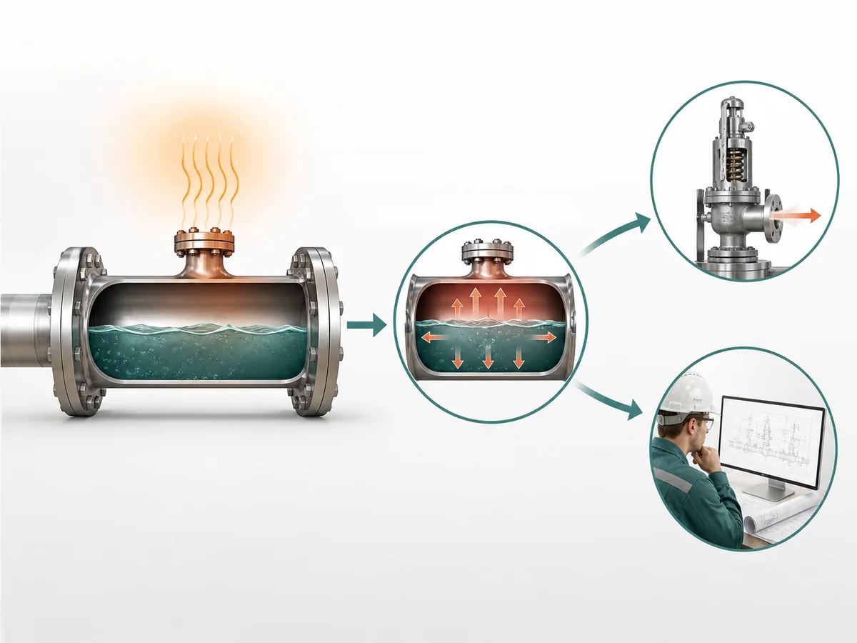
La decisión de ingeniería inmediata no es, por tanto, un cálculo de capacidad. Es si la combinación de confinamiento del líquido y una condición de calentamiento creíble crea un deber de alivio térmico o hidrostático que requiere más ingeniería.
Por qué este deber es diferente del alivio por incendio en recipientes
El sistema protegido define el problema. Para una línea aislada, el punto de partida es un segmento de tubería de líquido confinado y una condición de calentamiento que afecta a ese segmento. Un escenario de emergencia o incendio en un recipiente de almacenamiento parte de un sistema protegido diferente y de una base de alivio diferente.
El hecho de que ambos problemas puedan involucrar equipos de alivio de presión no hace que uno sea sustituto del otro. No se debe suponer que un sistema de alivio de recipiente protege una línea de líquido que puede aislarse fuera del límite de alivio efectivo del recipiente.
Qué significa “calentamiento creíble” en esta etapa
Una condición de calentamiento creíble es una condición real del proyecto capaz de aumentar la temperatura del líquido mientras la sección identificada permanece aislada. Debe derivarse de la base de instalación y operación, y no de un ejemplo genérico de alivio térmico.
HSE guidance identifies external heat, temperature gradients and temperature cycling as conditions that may deserve review where they apply. OSHA also recognizes abnormal external heat exposure in defined LPG installation contexts. These sources support the need to examine real warming mechanisms; they do not establish one universal list for every LPG line.
La secuencia útil es, por tanto: primero establecer que el segmento puede quedar aislado y, a continuación, identificar la condición que puede calentarlo mientras está aislado. Si se desconoce la base de calentamiento, manténgala como una entrada de proyecto sin resolver en lugar de sustituirla silenciosamente por un escenario supuesto.
¿Cómo se define el segmento protegido y la condición de calentamiento creíble?
Establecer los límites físicos del segmento protegido
Comience con la línea que contiene líquido o la sección del equipo y trace en ambas direcciones hasta que se comprendan los límites de aislamiento efectivos. Luego, localice la conexión de alivio prevista en relación con esos límites.
La revisión de límites debe responder:
- ¿Qué sección física puede retener líquido?
- ¿Qué puntos de aislamiento pueden encerrar esa sección?
- ¿Bajo qué estado de válvula relevante ocurre el encierro?
- ¿La conexión de alivio prevista permanece en el lado protegido de esos límites?
Un P&ID es un punto de partida, no un sustituto de la filosofía de operación y mantenimiento. Cuando el estado del dibujo y la práctica de aislamiento real aún no están conciliados, el límite protegido permanece sin resolver.
Compruebe qué estados de la válvula pueden aislarla realmente
Revise los estados que pueden cambiar el límite de este segmento en lugar de ampliar la tarea a un inventario de válvulas de toda la planta. Una línea puede permanecer conectada durante la operación normal, pero quedar cerrada durante el mantenimiento. Por el contrario, los puntos de aislamiento mostrados en un dibujo no demuestran que el líquido quede atrapado en todos los estados.
Ask whether this actual valve state can confine liquid between effective boundaries while the section is exposed to the warming condition under review.
A “yes” identifies a scenario requiring thermal-relief review. An unknown valve state, liquid condition or boundary remains an information gap. It should not be converted into either a positive or negative selection conclusion.
Identify the Warming Condition Engineering Must Evaluate
Pair the protected boundary with the project condition that can warm the liquid while that same boundary exists. This avoids evaluating a warming condition that occurs only when the line is open, or an isolation state that is never exposed to the proposed warming mechanism.
The decision basis can be expressed qualitatively as:
protected segment + relevant isolation state + credible warming condition.
This is a boundary-definition framework, not a sizing formula. Detailed relief calculations belong after the scenario and its project inputs have been established.
How Should the Thermal-Relief Discharge Path Be Defined?
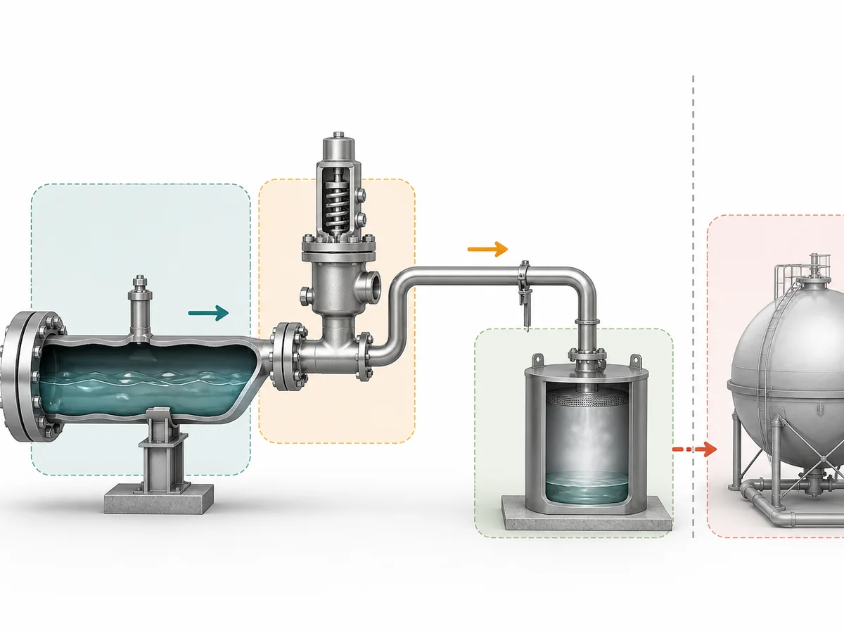
Identify the Intended Discharge Destination
A relief device is not fully defined by its connection to the trapped segment. The engineering basis also needs to state where relieved LPG is intended to go.
OSHA’s LPG requirements provide a scope-specific example in which hydrostatic relief from specified liquid piping is directed to a safe atmosphere. That requirement should not be generalized beyond its applicable jurisdiction and system scope. Where another pressure-containing or product-retaining system is proposed as the receiving destination, the connected-system conditions must be carried into the appropriate engineering review rather than treated as automatically acceptable.
The practical conclusion is that the project must establish the intended destination under its applicable requirements and receiving-system conditions before treating the relief path as resolved.
The relief path remains unresolved until the receiving destination and its applicable project boundary are known.
Identify Downstream Pressure or Back-Pressure Conditions
When the outlet enters another pressure-containing or product-retaining system, that receiving system can impose conditions at the relief-device outlet. Those conditions are therefore part of the engineering input to later device and installation review.
The project package should identify the receiving system and the relevant downstream pressure condition rather than describing the outlet only as “closed” or “connected.” Detailed acceptability of the connected network remains a separate downstream-system analysis.
American Petroleum Institute (API) pressure-relief installation guidance treats installed relief arrangements as an engineering-analysis subject. This page therefore does not establish an allowable back pressure, size a return path, or design a disposal, recovery or shared relief network; those decisions remain with the appropriate downstream engineering owner.
Route Closed-System Questions to the Appropriate Downstream Analysis
A product-retaining or other closed receiving system should not be interpreted as acceptable merely because a physical connection is available. The relevant question for this article is whether the destination and downstream condition are sufficiently defined for the next engineering decision.
- If the destination is not established, retain it as an RFQ or project-data gap.
- If the outlet connects to another pressure-containing system, identify the downstream condition for the responsible system analysis.
- If acceptability depends on connected-network hydraulics, route that question to the downstream relief-system owner instead of solving it inside this page.
Phase change remains conditional. If project-specific fluid and downstream conditions make a phase transition material to the relief analysis, it should be addressed in the separate sizing or downstream-system review. It is not treated here as a universal selection gate for every trapped-liquid LPG line.
How Do You Verify Liquid-Service Suitability and Keep the Relief Path Available?
Confirm That the Proposed Device Is Intended for the Required Liquid-Service Duty
Broad LPG service wording is not enough to establish suitability for a blocked-in liquid thermal or hydrostatic relief duty.
UL Standards & Engagement recognizes hydrostatic relief valves as an LP-Gas relief-device category, while PNGRB separately addresses suitable thermal pressure relief where liquid can be trapped. The procurement implication is limited but important: suitability for this duty should be supported directly rather than inferred from a generic LPG valve-family description.
Device review therefore starts with the system basis already defined in the earlier sections: the protected segment, liquid condition, warming scenario, intended discharge destination and relevant downstream condition. Product-specific suitability can then be confirmed against that basis by the responsible supplier or engineering reviewer.
Check Whether Isolation Can Disable the Relief Path
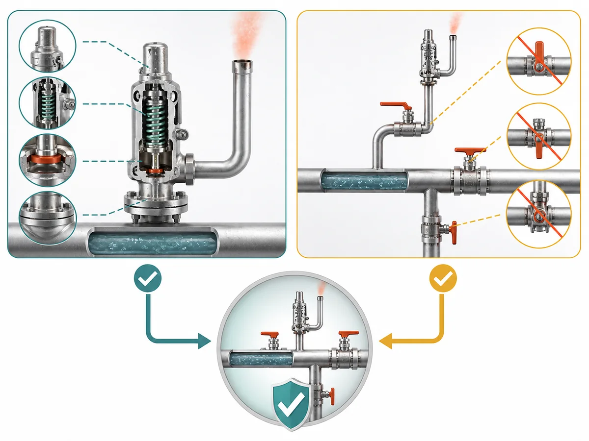
Device suitability does not protect the trapped segment if the installed arrangement can disconnect that device from the segment in the state when relief is needed.
Within the directly frozen U.S. OSHA LP-Gas scope, arrangements that can isolate a relief device from protected equipment or piping are restricted unless the required relief path is preserved. HSE process-pipework guidance separately identifies isolation-valve location as an important consideration where trapped-liquid thermal expansion is possible.
For each relevant operating or maintenance state, check whether an effective isolation boundary can separate the intended relief connection from the trapped liquid segment.
If it can, the arrangement is not resolved by this article. Its acceptability has to be established under the applicable project and jurisdictional requirements. The exact acceptable isolation arrangement is deliberately not generalized here.
Keep Installation Review Separate From Generic Valve Selection
Two confirmations are required, and one cannot substitute for the other:
- Duty suitability: evidence for the proposed device supports the intended trapped-liquid LPG thermal or hydrostatic service.
- Path availability: the installed isolation arrangement keeps the intended relief path connected to the protected segment in the relevant state, subject to applicable project requirements.
Keeping these questions separate prevents a common reasoning error: choosing a nominally relevant device and then treating installation availability as automatically proven.
What Information Should Go Into an LPG Thermal-Relief RFQ?
The RFQ should allow each responsible party to see what is already established, what still needs confirmation and who owns the unresolved decision. It should not force the supplier to reconstruct the protected boundary from a generic valve description.
| Input group | Información del proyecto | Primary confirmation responsibility | Decision supported |
|---|---|---|---|
| Protected segment | P&ID or line identification, liquid-containing section and effective isolation boundaries. | Project or piping engineering establishes the system boundary. | Defines exactly what section requires review. |
| Isolation states | Relevant normal, operating and maintenance valve states. | Project or operating basis establishes when the section can become enclosed; installation review checks relief-path availability. | Connects the protected boundary to the state in which relief may be required. |
| Fluid and operating basis | Available LPG fluid definition, confirmation of liquid service, and the project’s pressure and temperature basis. | The project supplies the service basis; the device reviewer evaluates suitability against it. | Prevents device suitability from being inferred from a generic LPG label. |
| Credible warming | The actual project condition capable of warming the liquid while the segment is isolated. | The project establishes the credible scenario. | Defines the thermal-expansion duty that later engineering must evaluate. |
| Relief destination and downstream condition | Proposed relief location, intended receiving destination and relevant downstream pressure condition. | The project identifies the destination; the responsible downstream-system owner resolves connected-system effects where required. | Separates valve-duty definition from closed-system or downstream-network analysis. |
| Compatibility and project requirements | Applicable fluid-compatibility requirements, project requirements, jurisdictional basis, isolation philosophy and required documentation. | The project supplies its requirements; the supplier or engineering reviewer confirms the device-specific evidence. | Establishes what must be demonstrated rather than assumed during final selection. |
Protected-Segment and Operating Information
Project or piping engineering should provide enough information to reconstruct the protected boundary: the relevant line or P&ID reference, the section that can contain liquid, the effective isolation points and the valve states that can enclose it.
Fluid and operating information belongs with that boundary. These inputs establish the service basis for later engineering; they do not themselves prove a device result.
Warming, Discharge and Downstream Information
The project should state the credible condition that can warm the trapped liquid, the intended relief-device location and the proposed receiving destination.
Where the outlet enters another system, the relevant downstream condition should also be supplied or explicitly assigned for separate analysis. An unknown warming basis, destination or downstream condition should remain visible as an unresolved field rather than being replaced by a generic assumption.
Compatibility, Project and Isolation Requirements
The RFQ should distinguish requirements supplied by the project from evidence that the device reviewer must confirm. Project inputs include the applicable service, compatibility requirements, jurisdictional or project basis, isolation philosophy and documentation expectations.
The responsible supplier or engineering reviewer can then assess device-specific suitability against those inputs. This preserves the difference between stating the service requirement and claiming that a particular product satisfies it.
What the Supplier Must Confirm Rather Than the Buyer Assume
The buyer or project team owns the system basis: what can become trapped, when the boundary exists, what can warm the liquid, where relief is intended to go and which project requirements govern the review.
The supplier or engineering reviewer owns the device-specific confirmation needed to show that a proposed device is suitable for that submitted duty. When the outlet joins another pressure-containing system, the responsible downstream-system owner retains the connected-system analysis.
Do not close the RFQ by assuming that:
- a generic LPG valve description proves liquid thermal or hydrostatic relief suitability;
- a proposed discharge destination is acceptable before its project and receiving-system boundary is established;
- the relief connection remains available through every relevant isolation state without checking the installed path;
- missing boundary, warming, service or downstream information can be replaced with generic data.
A technically useful RFQ therefore does more than request a valve. It gives each reviewer enough evidence to identify the blocked-in duty, separate confirmed inputs from unresolved ones, and assign the remaining engineering decisions to the correct owner before final selection.