Scopri come definire uno scenario di sfioro con uscita bloccata, determinare la portata di scarico richiesta, distinguerla dalla capacità della valvola e verificare le condizioni di ingresso, contropressione e documentazione.

A blocked outlet relief scenario should start with the protected system and the credible source of overpressure, not with a nominal safety-valve size. The engineering sequence is to define the pressure boundary, determine whether flow, pressure, or energy can continue entering that boundary after the outlet becomes unavailable, establish the required relieving load at the applicable relieving conditions, and only then verify that the selected relief device and its inlet and discharge system can handle that requirement.
That distinction matters because a “blocked outlet” is only the initiating condition. It does not by itself define the relief rate. The result can change with the pressure capability of the upstream source, the performance of a pump or compressor as system pressure rises, whether any alternative flow path can legitimately be credited, the fluid phase and relieving temperature, and the pressure losses on both sides of the relief valve.
The practical objective is therefore not simply to answer “What size safety valve is required?” It is to build a traceable chain from the credible overpressure scenario to the required relief load, and from that load to documented valve capacity and installed-system suitability.
Confine ingegneristico: The discussion below explains a general blocked-outlet relief-review method. It does not replace a project-specific relief calculation, the governing code or project specification, manufacturer capacity data, or jurisdictional acceptance. The applicable standard edition and project pressure basis must be confirmed for the actual installation.
Blocked Outlet Relief Scenario: Define the Protected Boundary
The first decision is not the valve size. It is the boundary being protected.
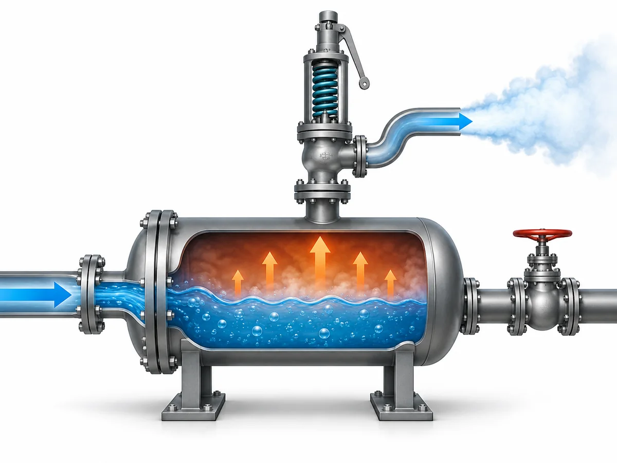
A process vessel, heat exchanger side, separator, piping segment, compressor discharge system, skid, or other pressure-containing system may be connected to several inlet and outlet paths. Closing one downstream valve does not automatically tell you which equipment will pressurize, which volumes remain connected, or which sources can continue adding mass or energy.
Start with the current process arrangement and identify the protected pressure boundary. That means establishing which equipment and piping remain pressure-connected during the blocked condition, where the restriction or closure occurs, which isolation valves are open or closed in the credible scenario, and which inlet sources remain capable of feeding the system.
This system view prevents a common sizing error: taking the flow through one line during normal operation and assuming that it is automatically the blocked-outlet relief requirement. Normal operating flow describes one operating state. A blocked outlet creates a different pressure-flow condition, and the source may respond differently as pressure rises.
The same reasoning applies to alternative outlets. A parallel process route, recycle line, bypass, vent, control valve, or other flow path should not be credited simply because it appears on the P&ID. Its actual availability and hydraulic capacity must be defensible for the scenario being evaluated.
A useful way to frame the boundary is to ask four questions:
- What pressure-containing equipment is being protected?
- What outlet or flow path becomes blocked or materially restricted?
- What sources can continue adding pressure, flow, or energy?
- What other paths can actually remain available under the same credible event?
Until those questions are answered, the relief-load calculation is not yet anchored to a defined system.
Decide Whether the Blocked Outlet Is a Credible Overpressure Case
A closed outlet is a physical condition. A credible relief scenario additionally requires a mechanism that can raise pressure in the protected boundary.
The central comparison is therefore between the pressure capability of the credible source and the pressure basis of the protected equipment. If the remaining pressure or energy source cannot drive the protected system above its allowable pressure basis, the blocked outlet may not create the governing overpressure case. If it can, the next task is to quantify the relief demand.
This distinction becomes important when the source is not a constant-pressure supply.
A centrifugal pump, for example, does not produce one fixed combination of flow and pressure across its entire operating range. As downstream resistance increases, the operating point moves on the pump and system curves. At shutoff, the pump reaches a zero-flow condition. Shutoff head can therefore help establish whether the pump is capable of developing enough pressure to create an overpressure problem, but it is not itself the relieving flow.
That means two different questions must remain separate:
- Can the source generate enough pressure to make the scenario credible?
- How much flow can the source deliver at the pressure relevant to the relief calculation?
The same principle applies more broadly, but the actual source model is equipment-specific. Compressor performance, control-valve flow, a high-pressure upstream vessel, utility pressure, or another process source cannot simply inherit a centrifugal-pump calculation method. Each source must be evaluated using the performance relationship that is relevant to that source and the actual relieving condition.
Do not take automatic credit for trips or interlocks
A high-pressure trip, shutdown, control interlock, automatic isolation valve, recycle system, or alternate pressure-protection path may affect the scenario analysis. Its presence, however, is not automatically sufficient reason to reduce or eliminate the required relief duty.
Any credit must be supported by the applicable code or project methodology and by the actual protection architecture. Depending on the project, that may involve questions about independence, reliability, valve fail position, response to the initiating event, available hydraulic capacity, and documentation.
The safe writing and engineering boundary is straightforward: a safeguard can affect the blocked-outlet analysis only when the governing basis permits that credit and the protection function has been demonstrated for the scenario.
Without that confirmation, the relief analysis should not quietly assume that the control system will always prevent overpressure.
Establish the Required Relieving Load at Relieving Conditions
Once the scenario is credible, the next task is to determine the process-side relief requirement.
The required relieving load is fundamentally a system balance. The analysis asks how much mass or energy can continue entering the protected pressure boundary, what flow can legitimately leave through any other credited path, and what net accumulation must be removed by the relief system to prevent unacceptable pressure rise.
That is why normal operating flow is not automatically the right answer.
For a blocked-outlet case driven by a pump, compressor, upstream pressure source, or control-valve-fed system, the relevant inflow should be based on credible source behavior as the protected system approaches the applicable relieving condition. The exact method depends on the source.
For a centrifugal pump, this usually means examining its pressure-flow performance rather than substituting either the normal operating flow or the shutoff point as the relief rate. Shutoff establishes a zero-flow pressure capability. The credible flow at a lower pressure on the same performance relationship may be quite different.
For another type of source, different information may control the result. A compressor can require performance-map and control-system information. A control valve can require the actual upstream pressure, downstream relieving pressure, fluid state, and valve-flow data. A pressure vessel feeding another system can require an evaluation of the available pressure and flow path. The article should not collapse these different mechanisms into one generic formula.
Remaining outflow must be defensible
Suppose the normal outlet is blocked but another path remains open. It may be tempting to subtract that path’s normal flow from the incoming flow and call the difference the relief requirement.
That is only justified when the remaining path is actually available during the scenario and its capacity at the relevant pressure condition has been established. A path that becomes restricted, changes control position, shares the initiating failure, or has insufficient hydraulic capacity cannot safely be treated as guaranteed relief.
A partially restricted outlet deserves the same caution. It is not automatically equivalent to either a fully open system or a completely blocked one. The remaining hydraulic capacity has to be modeled or otherwise established for the credible condition.
Relieving state matters
The calculation also has to represent the fluid condition at relief, not merely the normal operating condition.
Relevant variables can include:
- medium and composition;
- liquid, vapor, gas, steam, or another applicable phase;
- pressione di scarico;
- temperatura di scarico;
- density and other required fluid properties;
- flashing or two-phase behavior when physically credible.
A blocked outlet should not automatically be assumed to be a liquid-only or vapor-only case. The system physics decide the relieving state.
A useful process-side review can therefore be summarized as follows:
| Domanda tecnica | Cosa deve essere stabilito | Perché cambia la decisione |
|---|---|---|
| What remains connected? | Protected equipment, piping, isolation state and alternate paths | Defines the pressure boundary |
| What keeps feeding it? | Pump, compressor, control valve, vessel, utility or other source | Establishes the overpressure mechanism |
| Can that source exceed the protected pressure basis? | Credible source pressure capability | Determines scenario credibility |
| What can the source deliver at relief conditions? | Source performance at relevant pressure/state | Establishes inflow |
| Can any other path be credited? | Availability and hydraulic capacity | Changes net accumulation |
| What is the fluid state at relief? | Phase, temperature and relevant properties | Changes the sizing basis |
| What is the final net load? | Credible inflow minus defensible outflow, as applicable | Becomes the required relieving load |
This table is a reasoning framework, not a substitute for the applicable calculation method.
Representative engineering scenario
Consider a process vessel that normally receives liquid from a centrifugal pump and discharges through a downstream line. If that outlet becomes unavailable while the pump continues to operate, the first question is whether the pump can raise the vessel pressure above its protected pressure basis.
If the answer is yes, shutoff head alone still does not define the relief rate, because pump shutoff is a zero-flow condition. The required relief analysis instead needs the pump’s credible flow at the pressure corresponding to the relief calculation, together with any legitimate residual outflow from the protected boundary.
The example intentionally contains no project pressure, flow rate, valve model, or result. Those values must come from the actual system.
Keep Required Relief Load, Flow Area, and Valve Capacity Separate
After the required relieving load has been established, the engineering problem changes from system demand to relief-device verification.
These stages should not be merged.
Carico di sfioro richiesto is the amount the protected system needs the relief path to handle for the governing scenario.
Area di flusso richiesta is the flow area calculated from that requirement using the applicable sizing method and relieving conditions.
Selected orifice or effective flow area is a characteristic of the selected relief device.
Capacità di sfioro certificata o documentata is the performance basis used to verify that the selected device can actually meet or exceed the system requirement under the applicable conditions.
These values are related, but they are not interchangeable.
Most importantly, connection size is not capacity. A valve with an inlet flange that physically matches an existing nozzle has not thereby demonstrated sufficient relieving area or capacity. Likewise, the fact that two valves share the same set pressure does not establish that they have the same orifice, certified capacity, blowdown behavior, or back-pressure response.
The capacity check should therefore read logically in one direction:
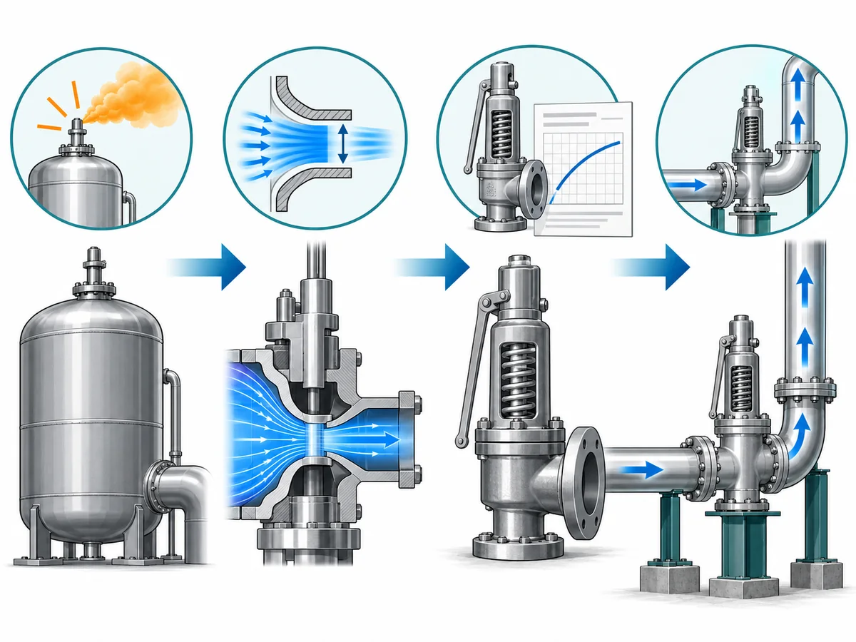
credible scenario → required relieving load → required sizing basis → selected device → documented capacity verification
That sequence also clarifies the division of responsibility between process analysis and product data. The process or relief study establishes what the system requires. The selected manufacturer’s documentation establishes what the exact valve configuration can deliver.
For final acceptance, the device identity needs to be specific enough that the capacity basis actually applies to the valve being considered. Depending on the applicable system, relevant identity can include the valve series, orifice or effective flow area, set pressure, service medium, relieving conditions, and the applicable capacity certification or documentation basis.
A catalog connection dimension or a visually similar valve is not an adequate substitute.
Check the System Conditions That Can Change the Capacity Decision
A valve can appear adequate when compared only with the required process load and still require further engineering review once it is placed in the actual relief system.
Il inlet and outlet piping form part of that installed system.
Inlet pressure loss can affect valve stability
Pressure is lost between the protected equipment and the relief-valve inlet when flow passes through the inlet piping. Excessive nonrecoverable loss can create an unfavorable interaction between vessel pressure and the pressure seen at the valve inlet, contributing to unstable cycling or chatter.
For projects governed by API 520 Part II, the current publicly identified edition uses a 3% nonrecoverable inlet-pressure-loss baseline at maximum discharged flow, while also providing for an engineering-analysis approach in appropriate installations. That number should not be transferred blindly to every code, jurisdiction, valve configuration, or engineered exception. The project edition and device/application basis still have to be confirmed.
The practical lesson is broader than the number: do not finish the blocked-outlet analysis at the process nozzle. Verify the pressure loss through the actual inlet path at the required relief flow.
Long inlet piping, unnecessary restrictions, undersized fittings, isolation arrangements, or other sources of resistance can therefore change whether an otherwise adequate relief-device selection remains acceptable.
Back pressure belongs in the capacity review
The discharge side requires similar attention.
A relief valve can experience:
- contropressione sovrapposta, which exists at the outlet before the valve opens; and
- contropressione accumulata, which develops because relieving flow passes through the discharge piping or header.
Those pressures can influence valve behavior, available differential pressure, capacity, stability, set/reseat behavior, or the suitability of a particular valve configuration. The exact effect depends on the valve design and the manufacturer’s documented limits.
This is why selecting a balanced-bellows or pilot-operated valve should not be described as an automatic solution to back-pressure effects on spring-loaded safety valves. Those designs have their own application limits, and the actual discharge condition must still be evaluated.
If multiple relief devices discharge into a common header, the blocked-outlet case should also be checked against credible simultaneous loads. Loads should not simply be summed because several valves exist, nor should simultaneous relieving be dismissed without analysis. The governing scenario determines whether the events can occur together; the resulting discharge-system condition determines the corresponding back pressure.
Relieving conditions must remain consistent across the calculation
The process-side required load, device-sizing calculation, manufacturer-capacity verification, and discharge-system review should all refer to a consistent set of relieving conditions.
A calculation based on one phase and temperature cannot safely be verified against capacity data that assumes a materially different state unless the applicable sizing or capacity basis explicitly accounts for that difference.
This consistency check is often more important than adding another formula. It catches a class of errors in which individually reasonable values have been taken from different conditions and combined into one apparently complete calculation.
Close the Review with Calculation, Capacity, and Documentation Checks
A blocked-outlet review is ready for engineering acceptance only when the scenario, required load, relief-device data, and installed-system assumptions can be traced to a coherent basis.
The final review should make clear what has been calculated, what has been selected, what has been documented by the manufacturer, and what remains project-dependent.
A focused review package should normally address the following items where applicable:
- the protected equipment and pressure boundary;
- the blocked or restricted outlet being evaluated;
- all credible continuing pressure or flow sources;
- the operating pressure and the applicable design-pressure or MAWP basis;
- the proposed set-pressure basis;
- the governing overpressure/accumulation basis;
- medium, phase, composition and relieving temperature as required;
- the required relieving-load calculation and its source assumptions;
- any credited alternate flow path or safeguard and the basis for that credit;
- the selected relief device and orifice/flow-area identification;
- the applicable manufacturer certified or documented capacity;
- inlet-piping pressure loss;
- superimposed and built-up back pressure as applicable;
- common-header effects where credible simultaneous relieving is involved;
- the governing code, standard edition and project specification;
- relevant calculation sheets, datasheets, drawings, nameplate information and required test or certification records.
Not every project will use the same document package. The point is traceability: another qualified reviewer should be able to follow the path from the blocked-outlet event to the required relief load and then to the proposed device and installed relief system.
That is also the information a valve manufacturer or engineering reviewer needs before making a meaningful capacity or configuration recommendation. Sending only nominal size, set pressure and connection dimensions leaves the most important part of the selection basis unresolved.
For procurement, the same distinction prevents an RFQ from turning an unfinished process-safety question into a product request. Required relieving capacity should be established or clearly identified as an outstanding engineering input; the supplier’s documented capacity can then be evaluated against it.
The strongest final question is therefore not, “Does this valve fit the line?”
Does the complete scenario-to-capacity chain demonstrate that this exact relief device, installed in this actual system, can protect the defined pressure boundary under the governing blocked-outlet condition?
If any link in that chain is still based on an assumption—scenario credibility, source performance, relieving state, safeguard credit, inlet loss, back pressure, or manufacturer capacity—the assumption should remain visible until it is verified.
In un caso di sfioro per uscita bloccata, è possibile considerare un arresto, un trip o un interblocco di controllo?
Potentially, but not automatically. Credit should only be taken when the governing code or project methodology permits it and the protective function has been shown to provide the required protection for the same credible scenario. Its independence, reliability, valve actions, response to the initiating event, and documentation may all matter. The mere presence of an interlock on a P&ID is not sufficient basis to remove a blocked-outlet relief load.
What changes if the outlet is restricted rather than completely closed?
A partially restricted outlet can retain some hydraulic capacity, so it should not automatically be treated as either fully open or fully blocked. The credible remaining flow has to be evaluated at the relevant pressure condition. If that residual outflow is to reduce the relief requirement, its availability and hydraulic capacity need a defensible calculation or project basis.
Why can pump, compressor, or upstream-source performance at relieving pressure matter?
Because the source may deliver a different flow as system pressure changes. For a centrifugal pump, for example, shutoff head is a zero-flow pressure condition; it can help determine whether the pump can overpressure the equipment, but it does not define the relief flow. The required relieving load should use the credible source performance at the relevant relieving condition. Other source types require their own appropriate performance basis.
Need to review a blocked-outlet relief case?
For an engineering review, send the protected pressure boundary, blocked-outlet location, medium and phase, operating and design/MAWP basis, proposed set pressure, credible source-flow or pressure data, required relieving-load calculation or available inputs, relieving temperature, inlet/discharge arrangement, back pressure, applicable code/project specification, and proposed or existing valve datasheet where available.
The objective is to verify the scenario and capacity basis before confirming a relief-device configuration or documented capacity.