Scopri come un carico di sfioro incontrollato, il flusso bifase, le incrostazioni, la contropressione e la capacità certificata influenzano la selezione e la verifica delle valvole di sicurezza dei reattori.

Reactor safety valve selection for runaway reactions begins with a validated relief scenario.
A reactor safety valve for a runaway reaction should not be selected from nozzle size, set pressure, or normal process flow first. The selection has to begin with the validated runaway-relief scenario: how much material must be relieved, at what pressure and temperature, in what phase, and under what installed inlet, outlet, and disposal-system conditions. Only after those conditions are established can an engineer determine the required flow area, screen the pressure-relief-device arrangement, and verify that a candidate valve has adequate documented or certified capacity for the actual duty.
That distinction matters because a runaway reaction can change more than the amount of flow. It can change the relieving phase, create vapor-liquid two-phase discharge, produce solids or polymers that threaten the relief path, and impose a discharge load very different from normal reactor operation. Back pressure and the downstream effluent-handling system can then change which valve configuration remains suitable.
This article starts where the reaction-hazard and relief-scenario analysis leaves off. It does not replace reaction calorimetry, kinetic analysis, a DIERS relief calculation, or the governing code review. Its purpose is to show how those upstream results are translated into a pressure-relief-device selection and verification package.
Reactor Safety Valve Selection: Why Runaway Reactions Change the Problem
For an ordinary valve replacement, engineers may begin with familiar identification data: inlet size, outlet size, set pressure, body material, valve type, or an existing model number. Those data are useful, but they do not define the protection requirement for a runaway reactor.
The governing question is not simply, “Which valve fits this connection?” It is, “What must the relief system pass if the credible runaway actually develops?”
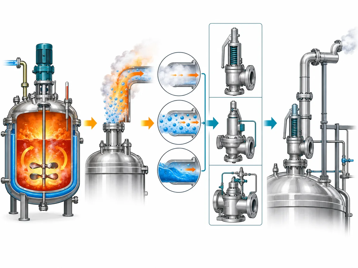
A runaway reaction can accelerate heat generation and gas or vapor production faster than the process can remove them. Depending on the chemistry and inventory, the event may also involve boiling, flashing, foaming, entrainment, decomposition products, or solids. The pressure-relief device therefore has to be evaluated against the abnormal relieving state, not only against normal operation.
credible runaway scenario → required relief duty → relieving state → required flow performance → device arrangement → installed-system verification
Skipping the early steps can create a false sense of certainty. A valve can have the correct flange size and set pressure yet still lack the required capacity. A valve with adequate catalog capacity under one fluid condition may not have an applicable capacity basis for a different phase or relieving temperature. And a valve that appears adequate as an isolated component may behave differently when connected to a restrictive discharge system.
The first selection rule is therefore simple: define the runaway duty before selecting the hardware.
Build the Runaway Relief Basis Before Selecting the Device
The pressure-relief-device engineer should receive a defined engineering basis from the upstream reactive-hazard work. The exact analysis depends on the process and governing project requirements, but the handoff normally needs to establish several things before valve selection becomes meaningful.
First, the credible runaway scenario must be identified. That may involve an uncontrolled reaction, decomposition, loss of cooling, incorrect reactant addition, contamination, or another project-defined initiating condition. This article does not determine which scenario governs; it assumes that process-safety analysis has already established the basis that must be relieved.
Second, the analysis must establish the required relieving load or accepted calculation basis. Normal vapor generation, normal vent flow, or pump capacity should not be substituted for the emergency relief demand unless the engineering analysis demonstrates that they represent the governing case.
Third, the relieving conditions have to be defined. At minimum, the valve-selection process may need the relieving pressure, relieving temperature, reaction-mixture composition, and expected phase at the relief device.
These conditions form the interface between reactive-process analysis and mechanical pressure-relief-device selection.
A useful way to separate responsibilities is:
| Voce tecnica | Cosa stabilisce | Cosa non stabilisce da sola |
|---|---|---|
| Runaway scenario | The abnormal event to be protected against | Valve size or model |
| Portata di scarico richiesta | Required emergency flow duty | Certified valve capacity |
| Pressione e temperatura di scarico | Conditions for sizing and service screening | Material compatibility by themselves |
| Relieving phase | Applicable flow/sizing basis | Actual selected orifice |
| Set-pressure requirement | Intended pressure setting under the governing basis | Capacità richiesta |
| Valve connection size | Interfaccia fisica | Flow area or certified capacity |
| Manufacturer capacity data | Device performance under stated conditions | Suitability for every reactor installation |
The practical consequence is important: if the required runaway load or relieving state is still unknown, selecting a final valve is premature. The correct output at that point is not a guessed model; it is a list of unresolved engineering inputs.
Two-Phase Relief Can Change the Selection Problem
One of the most consequential questions in runaway-relief design is whether the discharge should be treated as single-phase or two-phase.
A runaway case should not automatically be assumed to relieve vapor only. Depending on the reaction system, the relief stream may include liquid carried with the vapor, flashing liquid, foam, or a vapor-liquid mixture. That matters because the flow behavior through the relief device changes, and the sizing method used for an ordinary gas or vapor case may no longer represent the governing duty.
relieving phase → applicable flow model → required flow area → device-capacity verification
This does not mean every runaway reaction requires a two-phase calculation. The expected phase must come from the reactive and thermodynamic analysis. The important selection rule is that the phase should be established rather than assumed.
A representative engineering scenario
Consider two otherwise similar reactor relief reviews. In the first, the validated analysis shows that the governing relief stream is predominantly vapor. In the second, the same general type of reactor has a runaway scenario that can carry a substantial liquid fraction into the relief path.
The inlet connection might be the same in both cases. The set pressure might also be the same. Yet the sizing and capacity-verification path can be different because the fluid entering the relief device is different.
The example is conceptual rather than a recorded project result. Its purpose is to show why nominal valve data cannot substitute for a validated relieving-phase basis.
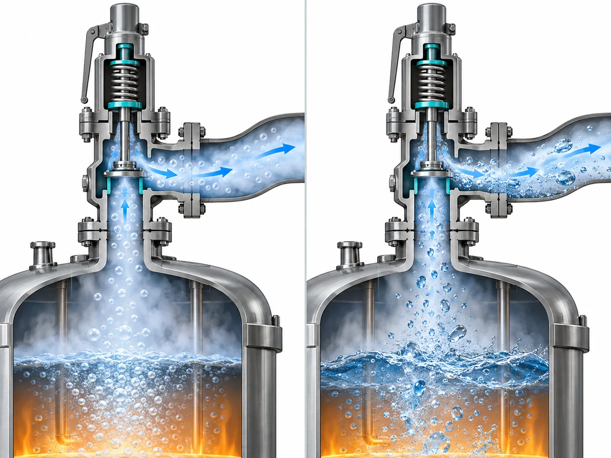
Where two-phase discharge is credible, the engineering review should identify the recognized sizing method being used and the assumptions behind it. A generic percentage added to a vapor capacity is not a defensible substitute for that analysis.
When Fouling, Polymerization or Solids Can Change the Relief Arrangement
Required capacity is only useful if the relief path remains available when the emergency occurs.
Reactive systems can present a problem that is less important in clean gas service: the relieving material itself may foul or obstruct the inlet, valve internals, or associated piping. Solids, crystallization products, high-viscosity material, or polymer formation can therefore become selection variables rather than secondary maintenance concerns.
The engineering question becomes:
Can the required emergency flow actually reach and pass through the relief device under the runaway condition?
A calculation that proves sufficient theoretical flow area does not answer that question if the process can create a credible blockage mechanism.
This is also where rupture disks may enter the engineering review. A rupture disk can be used with a pressure-relief valve in recognized combinations, but it should not be treated as an automatic solution to every fouling or polymerization problem. The combination has its own installation, interspace, pressure-loss, and capacity considerations, and the applicable combination-capacity basis must be verified where required.
The decision should therefore be conditional:
- If credible fouling or plugging is not present, do not introduce a more complex arrangement merely because the service is a reactor.
- If the process can create deposits, solids, polymers, or other restrictions, evaluate whether the relief path and device arrangement remain reliable.
- If a rupture disk and valve are used together, verify the combination rather than assuming that the bare valve’s documented capacity transfers unchanged.
Material selection belongs in the same screening process. Normal operating composition and temperature may not represent the fluid seen by the device during a runaway. Body, trim, bellows, spring, seat, seal, gasket, and rupture-disk materials therefore need to be checked against the actual relieving composition and temperature where those conditions can differ materially from normal operation.
This article cannot identify a universal alloy, seat type, or rupture-disk arrangement for runaway service. Those decisions require the actual chemistry and product data.
Back Pressure and Effluent Handling Can Constrain Valve Configuration
The safety valve is not an isolated component. Its outlet is connected to a relief system, and that system can affect both valve behavior and the safe handling of the released material.
Two back-pressure components are especially important to distinguish:
- contropressione sovrapposta, which exists at the valve outlet before the valve opens; and
- contropressione accumulata, which develops because flow through the downstream piping and disposal system creates resistance during relief.
The magnitude, variability, and source of that pressure can affect the selection review. A conventional spring-loaded valve, a balanced-bellows valve, and a pilot-operated valve do not all respond identically to every back-pressure condition. But the correct conclusion is not that one design “solves” back pressure.
Configuration has to be screened using the actual system conditions and the limits of the specific valve design.
For example, a balanced-bellows design can reduce the influence of certain outlet-pressure effects on the main valve mechanism, but that does not make it immune to all back-pressure or installation limitations. A pilot-operated system can offer different operating behavior, yet its main valve, pilot, sensing arrangement, and discharge conditions still have manufacturer-specific limits.
The outlet destination also matters independently of valve mechanics. Runaway relief may contain flammable, toxic, corrosive, hot, reactive, or two-phase material. The downstream engineering problem may therefore involve a flare, scrubber, separator, condenser, quench system, collection vessel, or another project-specific disposal arrangement.
The selection engineer does not need to redesign the entire effluent-handling system while choosing the safety valve. However, the valve cannot be confirmed without knowing enough about that system to establish the outlet pressure and whether the relief stream can be handled safely.
valve configuration selection and relief-system design are separate responsibilities, but they are not independent.
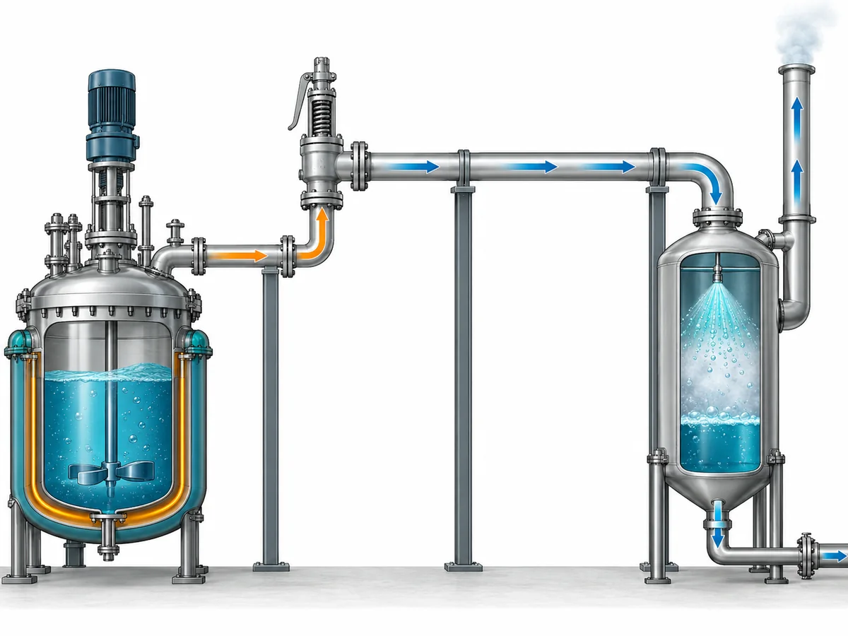
Inlet conditions require the same system view. Restrictive inlet piping can reduce pressure available at the device and contribute to unstable behavior. Exact acceptable inlet-loss limits, outlet-pressure limits, reaction forces, piping dimensions, and supports must come from the governing design basis and manufacturer data rather than from a universal number in a general article.
Verify the Selected Device Against the Actual Runaway Duty
Once the runaway scenario, relieving conditions, and installed-system constraints are defined, a candidate device can be evaluated. This is where several quantities that are often mixed together must remain separate.
Required relieving load is not certified capacity
Il required relieving load comes from the protected process and the governing relief scenario. It describes what the reactor needs the relief system to handle.
Il required flow area comes from applying the applicable sizing method to that duty and the relevant relieving conditions.
Il selected valve or orifice identifies a physical flow path.
Il documented or certified capacity is evidence of the selected device’s performance under its stated capacity basis.
These quantities form a verification chain; they are not interchangeable:
required relieving load ≠ required flow area ≠ selected orifice ≠ nominal connection size ≠ documented or certified capacity
A larger flange does not prove adequate capacity. The same set pressure does not prove the same capacity. A familiar orifice designation should not be assumed to transfer the same certified performance across different manufacturers, standards, product series, phases, or service conditions.
The selection is complete only when the candidate device’s applicable capacity is adequate for the required duty under the relevant basis.
Keep the pressure terms separate
Operating pressure, design pressure or MAWP, set pressure, overpressure, accumulation, and relieving pressure describe different parts of the pressure-protection problem.
For a reactor runaway article without a confirmed jurisdiction or project code, it is safe to explain the distinctions but not to publish a universal relationship or percentage and apply it to every reactor.
The project should instead identify:
- the protected equipment pressure limit;
- the governing code or project basis;
- the intended valve set pressure;
- the allowed pressure response for the governing scenario; and
- the relieving pressure used in the applicable sizing method.
The governing standard, edition, and project specification determine the exact acceptance relationship.
Check service compatibility at the relieving condition
The relieving state can be hotter, more reactive, more corrosive, or compositionally different from normal operation. A material grade that is acceptable at the normal process condition does not automatically prove that the entire valve is suitable for the runaway condition.
The review may need to distinguish among:
- body material;
- nozzle and disc or trim;
- spring and bellows materials;
- seat and seal;
- gasket;
- pilot components, if applicable; and
- rupture-disk materials, if a combination device is used.
The correct result may be “requires material review” rather than an immediate yes-or-no valve recommendation. That is a valid engineering outcome when the service chemistry is not yet defined.
Verification should end in evidence, not assumptions
Before a candidate valve is accepted for project review, the engineer should be able to connect the process requirement to product evidence.
A practical verification sequence is:
- confirm the governing runaway scenario;
- confirm the required relieving load and relieving state;
- confirm the sizing method and required flow area;
- identify the candidate device and flow path;
- confirm the applicable documented or certified capacity;
- confirm back-pressure and inlet-system compatibility;
- confirm materials and temperature suitability;
- confirm the applicable code, certification, and project documentation.
If one of those steps is unresolved, the unresolved item should remain visible rather than being hidden behind a model designation.
What to Send for a Reactor Runaway Relief-Device Review
A useful engineering review starts with the relief basis, not with a request such as “quote a DN50 safety valve.”
The information package should contain the inputs that can change the required capacity, configuration, materials, or installed behavior.
Reactor and scenario data
- protected reactor or pressure boundary;
- credible runaway scenario and initiating condition;
- relief-load calculation or reactive-hazard basis;
- required relieving rate, if already established;
- pressione di esercizio;
- pressione di progetto o MAWP;
- intended set-pressure requirement or basis;
- pressione di scarico;
- relieving temperature.
Process-fluid data
- reaction mixture and relevant composition;
- expected relieving phase;
- possible two-phase, flashing, foaming, or entrainment behavior;
- solids, crystallization, polymerization, viscosity, or fouling concerns;
- corrosive or otherwise material-critical constituents.
Installed-system data
- valve inlet piping and connection;
- outlet piping and connection;
- contropressione sovrapposta;
- built-up back-pressure basis or disposal-system information;
- destinazione dello scarico;
- existing rupture disk or other relief-device arrangement, if any.
Project and verification data
- governing code or standard, if confirmed;
- project specification;
- material requirements;
- certification or capacity-documentation requirement;
- inspection, test, and documentation requirements.
With those inputs, the review can answer a useful question: not merely whether a valve fits the nozzle, but whether the proposed pressure-relief-device arrangement can be verified against the governing runaway duty.
Domande Frequenti
È possibile utilizzare una valvola di sicurezza convenzionale a molla per una reazione incontrollata?
È possibile, ma il fatto che una valvola sia convenzionale e a molla non ne stabilisce di per sé l'idoneità. La scelta dipende dalla capacità di scarico richiesta in caso di fuga incontrollata, dalla fase di sfioro, dalle condizioni di ingresso, dalla contropressione, dalla pulizia del servizio o dal rischio di incrostazioni, dai requisiti dei materiali e dai limiti di prestazione documentati della valvola specifica. Una valvola convenzionale deve quindi essere valutata rispetto allo stesso scenario e alle stesse condizioni del sistema installato di qualsiasi altra configurazione candidata.
When does two-phase relief change reactor safety-valve selection?
It becomes a selection issue when the governing runaway analysis indicates that the relief stream can contain both vapor and liquid rather than behaving as a single-phase stream. That can change the applicable sizing method and required flow area. The relief phase should be established from the reactive and thermodynamic analysis; it should not be assumed simply because the equipment is a reactor.
When should a rupture disc be considered with a reactor safety valve?
A rupture disc may enter the review when the service presents issues such as credible fouling, polymerization, corrosion, leakage control, isolation, or other project-specific requirements. It is not automatically required for a runaway reaction. If a rupture disk and safety valve are used as a combination, the arrangement, installation, and applicable combination-capacity basis must be verified for the actual devices and governing project requirements.
Engineering Review Next Step
If the runaway-relief basis has already been established, send the relieving rate, relieving pressure and temperature, expected phase, process composition, fouling or polymerization concerns, inlet and outlet conditions, back pressure, discharge destination, material requirements, and governing project specification for engineering review.
The objective is to verify the pressure-relief-device arrangement against the real runaway duty before a valve model, capacity, or configuration is confirmed.