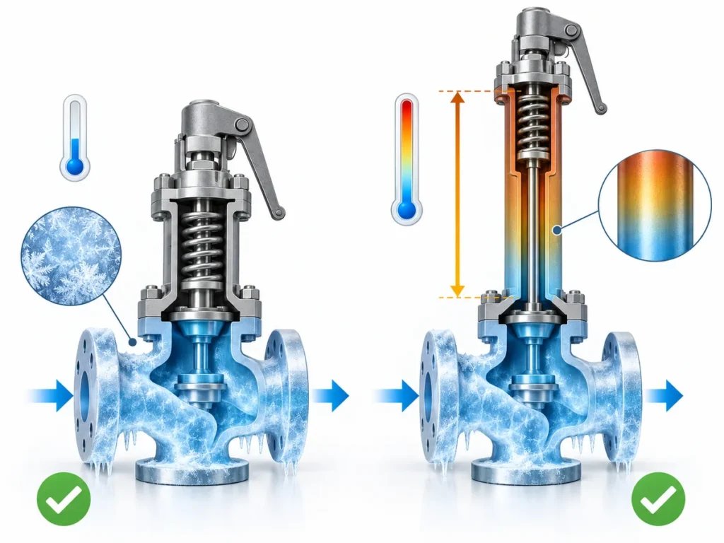
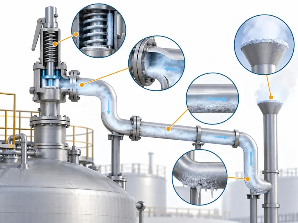
قارن بين مهام صمام التنفيس الحراري وصمام الأمان للضغط في أنابيب LNG/LPG، بما في ذلك السائل المحتجز، والسعة، والطور، والضغط الخلفي، وفحوصات طلب عروض الأسعار.

In LNG and LPG piping, a thermal relief valve and a pressure safety valve are not two opposite protection principles. A thermal-expansion relief valve is itself a pressure-relief device. The useful difference is the واجب التنفيس: what is causing pressure to rise, what section is being protected, and what load the device must relieve.
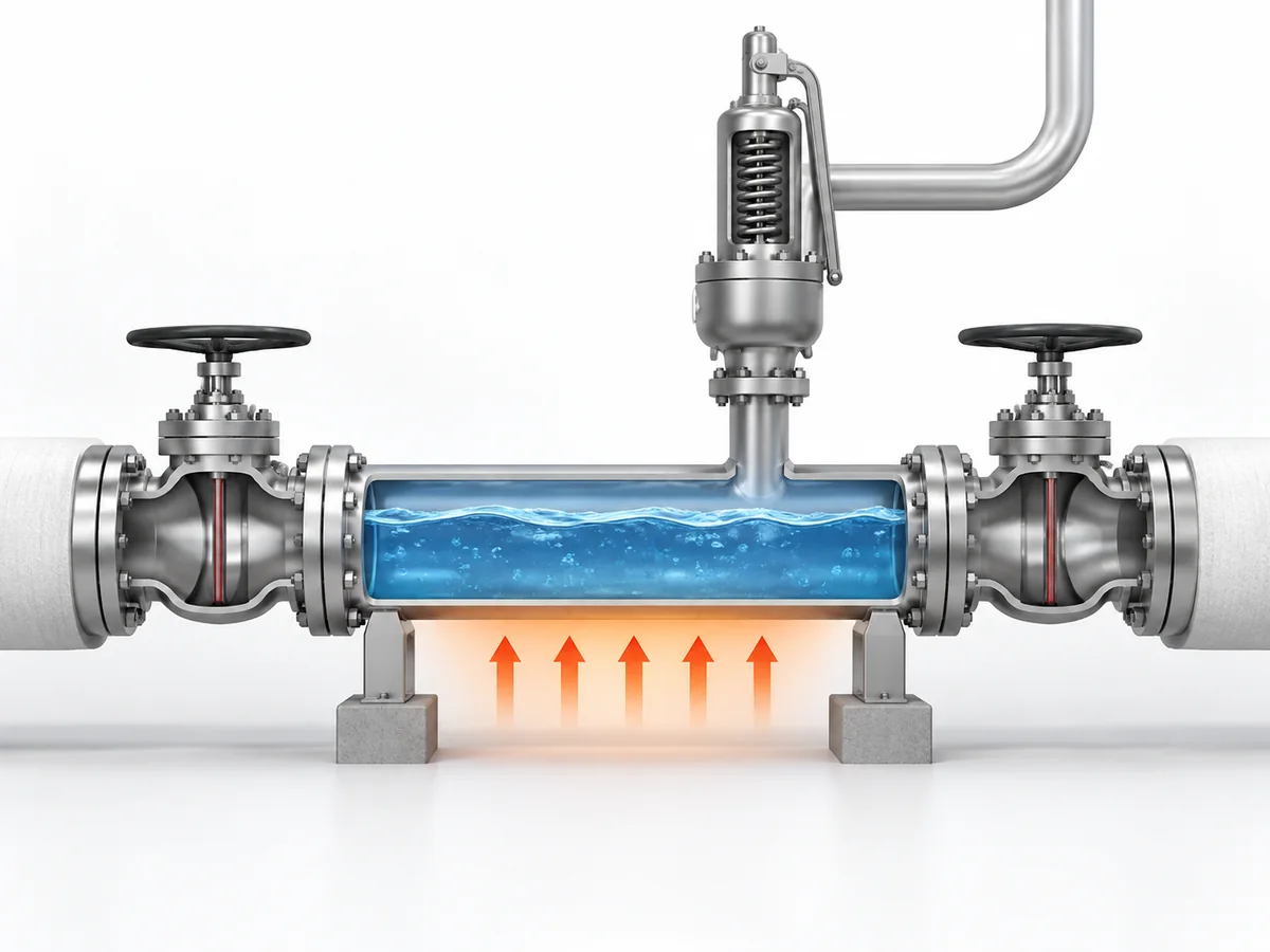
CGA PS-28 describes a thermal expansion relief valve as a pressure-relief device used on piping systems to prevent overpressure caused by thermal expansion of a limited trapped process-fluid volume, including cases involving cryogenic liquids or cold gases trapped between valves or other devices.
That leads to a more reliable engineering sequence: define the protected section → identify the credible pressure-rise mechanism → establish the required relief duty → verify the pressure-relief device and installed system.
A blocked-in liquid warming inside an isolated pipe section can create a thermal-expansion duty. Another system may instead have a blocked-flow, pump-related, vapor-generation, fire or other credible overpressure case. Those cases should not be collapsed into a single “TRV versus PSV” product choice. API 521 addresses overpressure causes, individual relieving rates and downstream disposal systems as parts of the pressure-relief-system problem.
The valve name is therefore a starting point—not the engineering specification.
Thermal Relief vs Pressure Safety Relief: What Is the Real Difference?
The real difference is duty first, hardware second.
A thermal-expansion relief duty exists because a trapped fluid changes condition and creates pressure as it warms.
The protective device still responds to pressure.
“Thermal” describes the cause of the overpressure; it does not turn the device into a temperature-operated valve.
CGA PS-28 makes that distinction especially clear by classifying the thermal expansion relief valve as a pressure-relief device.
“PSV,” “PRV,” “safety valve” and “relief valve” also should not be treated as universally interchangeable product classes.
ISO 4126-1, for example, is a product standard for safety valves rather than an application standard.
The governing project standard, datasheet and valve documentation therefore matter more than the abbreviation alone.
| نقطة المقارنة | Thermal-expansion relief duty | Other pressure-relief duty |
|---|---|---|
| Primary question | Can a trapped fluid volume build pressure as its condition changes? | What other credible mechanism can overpressure the protected system? |
| First thing to define | Isolated protected section and trapped inventory | Protected system and overpressure scenario |
| Does the valve name establish capacity? | لا | لا |
| Does pipe size establish required capacity? | لا | لا |
| What ultimately controls selection? | Required duty plus actual service and installed conditions | Required duty plus actual service and installed conditions |
For a broader terminology comparison, see the
PRV vs PSV vs safety valve vs relief valve guide.
This article only uses the terminology needed to make the LNG/LPG piping decision.
When Does LNG or LPG Piping Become a Thermal-Relief Case?
Start with the pressure boundary, not the valve catalogue.
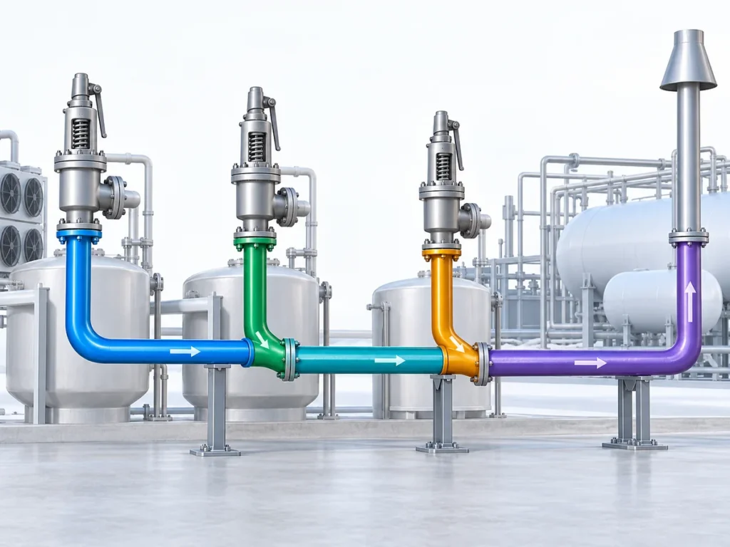
A thermal-relief case becomes a credible candidate when a finite fluid volume can become isolated and warming, thermal expansion or an applicable cryogenic state change can increase pressure while that section remains blocked in.
-
Define the protected section.
Identify the valves, equipment or other boundaries that isolate it. -
Confirm whether fluid can actually become trapped.
An LNG or LPG line does not become a thermal-relief case simply because the medium is liquefied gas. -
Establish the trapped fluid and state.
Liquid, cold gas and a potentially changing phase should not be assumed interchangeable. -
Identify the pressure-rise mechanism.
Determine whether warming or thermal expansion is actually the credible cause. - Only then establish the thermal-relief duty and required capacity.
Within its specific scope for LNG road-vehicle fuelling stations,
ISO 16924:2026
defines a thermal relief valve around protection against excess pressure caused by cryogenic liquid vaporization or by warming of cold gas trapped in an isolated pipeline section or other small component.
That definition is useful for understanding the LNG thermal-relief mechanism, but the standard’s fuelling-station scope should not be expanded into a universal rule for every LNG terminal or process plant.
A typical isolated section between two shutoff boundaries is easy to visualize, but it is not the only possible configuration.
What matters is whether the proposed relief device is connected to the actual volume that can become overpressured.
Identifying a thermal-expansion case also does يحدد complete the valve selection.
Set-pressure basis, required relieving capacity, phase, temperature, back pressure and discharge destination remain separate verification items.
When Is a Thermal-Relief Valve Not Enough?
A thermal-only assumption is no longer sufficient when another credible pressure-rise mechanism exists—or when the actual relieving condition has not yet been established.
API 521 addresses the principal causes of overpressure, individual relieving rates and the downstream disposal system rather than treating pressure relief as a catalogue-selection exercise.
Depending on the protected system, further review may be required when there is another process pressure source, a blocked outlet or continuing inflow, a pump-related overpressure condition, vapor generation or another significant phase change, external heat exposure where applicable, an undefined protected boundary, an unknown required relieving rate, or an uncertain liquid, vapor or two-phase relieving state.
The point is not to build a long list of every possible relief scenario.
It is to recognize when the thermal-expansion model no longer describes the complete problem.
Two-phase uncertainty is particularly important.
ISO 4126-10:2024
provides a dedicated sizing framework for gas/liquid two-phase flow in pressurized equipment and piping systems.
An unresolved LNG/LPG relieving condition therefore should not be silently forced into a single-phase assumption.
| If this is unresolved | لماذا هو مهم |
|---|---|
| Protected section | You do not yet know what the valve actually protects. |
| Credible relief cause | The required duty cannot be defined reliably. |
| سعة التنفيس المطلوبة | Connection size cannot substitute for sizing. |
| Relieving phase | Liquid, vapor and two-phase assumptions are not interchangeable. |
| Downstream conditions | Installed performance cannot be judged at the inlet flange alone. |
For the complete capacity calculation and certified-capacity workflow, use the
دليل حساب مقاسات صمامات الأمان وسعة التنفيس المعتمدة
rather than expanding this page into a sizing manual.
Can One Relief Device Cover Both Thermal Expansion and Other Overpressure Cases?
Possibly—but only after the relevant cases are checked independently.
Neither “the main PSV is larger, so it automatically covers thermal expansion” nor “thermal expansion always requires a physically separate valve” is a reliable selection rule.
API 520 الجزء الأول
addresses pressure-relief-device sizing and selection, while
API 520 الجزء الثاني
addresses installation.
The engineering review therefore needs to consider both the required duty and the installed system.
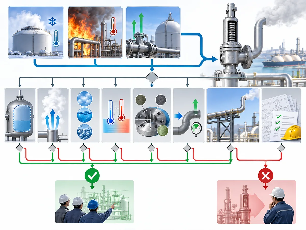
| سؤال التحقق | Why it can change the decision |
|---|---|
| Does the device protect the required boundary for each case? | A valve elsewhere in the system may not protect an isolated section. |
| Have the relevant relief causes been identified? | An omitted case cannot be covered by assumption. |
| Is the required relieving duty established for each applicable case? | Valve label and connection size do not establish load. |
| Does the candidate have appropriate capacity evidence? | Available capacity has to be compared with the required duty. |
| Is the relieving phase known? | A liquid case does not prove suitability for vapor or two-phase relief. |
| Is the set-pressure basis compatible with the protected system? | Opening pressure cannot be reviewed independently of the pressure boundary. |
| Are operating and relieving temperatures within documented limits? | Suitability at one temperature does not prove suitability at another. |
| Are body, trim, seat and seal arrangements supported for the service? | Component suitability is configuration-specific. |
| Are back-pressure conditions supported? | Outlet pressure can affect installed valve behavior. |
| Is the discharge path acceptable? | The valve is only one part of the complete relief path. |
| Are project documentation requirements satisfied? | Technical capability is not the same as project acceptance. |
What matters here is that capacity dominance is not the same as complete suitability.
A candidate with enough capacity for a larger-flow scenario may still need separate verification for a lower-flow thermal case if that case involves a different protected section, phase, temperature, component limitation, back pressure or discharge route.
Likewise, nothing in this comparison means thermal expansion always requires a physically separate device.
Whether one device can serve multiple duties is an engineering conclusion based on the complete system, not a rule that follows from the names “TRV” or “PSV.”
This is a candidate-screening principle, not a statement that one valve has already received project, code or regulatory approval.
What Changes Between LNG and LPG Relief Service?
LNG and LPG can use the same decision framework, but they should not inherit the same service assumptions.
The shared questions are straightforward:
What is protected?
What causes the pressure rise?
What fluid and phase reach the valve?
What capacity is required?
What temperature applies?
ما هو الضغط الخلفي الموجود؟
Where does the relieved fluid go?
What component and documentation evidence supports the candidate?
| Review variable | غاز طبيعي مسال | غاز بترول مسال |
|---|---|---|
| درجة الحرارة | Cryogenic exposure can become a primary suitability boundary. | Use actual operating and relieving temperatures; do not inherit LNG assumptions. |
| حالة المائع | Establish the actual LNG state at the protected section and during relief. | Establish actual LPG state rather than assuming liquid or vapor from the medium name. |
| Flashing / two-phase | Review when process conditions make it credible. | Review when process conditions make it credible. |
| المواد | Verify the configured valve for the required low-temperature duty. | Verify compatibility and actual temperature requirements. |
| المقعد / الإحكام | Low-temperature performance may become a model-level constraint. | Fluid, temperature and leakage requirements still control. |
| الضغط الخلفي | Check the installed outlet system. | Check the installed outlet system. |
| وجهة التفريغ | Define it for the actual project. | Define it for the actual project. |
Cryogenic pressure-relief equipment deserves model-level verification rather than a generic statement such as “stainless steel is suitable for LNG.”
Baker Hughes technical guidance on cryogenic pressure-relief valves
identifies construction materials, trim design, anti-galling measures and sealing features as cryogenic design considerations.
That evidence supports the need to verify the configured product; it does not establish that any specific ZOBAI model has the same construction or service capability.
For the broader application context, see
LNG and LPG pressure-relief applications.
For deeper component-level selection, see the
دليل اختيار مواد صمامات الأمان.
For engineering review, the same questions can be used for LNG and LPG, but the answers should be verified separately for the actual service.
What Should You Confirm Before Selecting a Valve or Sending an RFQ?
Do not send only “Need a thermal relief valve, LNG, DNxx.”
That does not define the protection duty.
A useful engineering enquiry should describe the system first and let the supplier verify the candidate second.
Define the protected system
- equipment or piping section being protected;
- isolation arrangement or system boundaries;
- credible overpressure scenario or scenarios;
- process reason pressure can rise.
Provide the process and relief basis
- medium and relevant composition;
- normal fluid phase;
- expected relieving phase;
- ضغط التشغيل؛;
- design or allowable pressure basis;
- required set-pressure basis;
- درجة حرارة التشغيل؛;
- minimum relevant service temperature;
- expected relieving temperature;
- required relieving rate or the approved calculation basis.
If the phase is uncertain or two-phase relief is credible, state that uncertainty rather than assuming liquid-only or vapor-only sizing.
Define the installed outlet conditions
- وجهة التصريف؛;
- downstream system or header;
- expected back pressure;
- relevant outlet piping restrictions;
- flare, vent, process-return or other project-defined destination where applicable.
State the mechanical and material requirements
- inlet and outlet connection requirements;
- pressure class;
- project material requirements;
- seat / seal requirements;
- medium compatibility requirements;
- leakage requirements;
- installation constraints.
Ask the supplier to confirm the candidate evidence
- exact model and configuration;
- pressure and temperature limits;
- construction materials;
- seat and seal arrangement;
- applicable relieving-capacity evidence;
- supported fluid / phase basis;
- back-pressure limitations;
- connection details;
- test and documentation package;
- conformity or certification only where it actually applies.
The buyer or process engineer defines the protected system and required duty; the supplier confirms what a specific valve configuration can support.
For the broader selection workflow, see the
دليل اختيار صمامات الأمان.
Classify the relief scenario before classifying the valve.
Once the protected boundary, relief cause, capacity, phase, temperature and installed conditions are defined, “thermal relief valve versus PSV” stops being a terminology debate and becomes a traceable engineering review.