تعرّف على كيفية حساب الضغط الخلفي المتراكم في أنابيب تصريف صمام الأمان، وتحديد الحدود الهيدروليكية، والتعامل مع تدفق السائل مقابل الغاز، والتحقق من النتيجة.

الضغط الخلفي المتولد هو الجزء من الضغط عند مخرج صمام الأمان الذي ينشأ بسبب مرور تدفق التنفيس عبر نظام التصريف في اتجاه المصب. وهو ليس نفس الضغط الموجود مسبقًا في مجمع مغلق قبل فتح الصمام. تصنف مصطلحات ISO هذا الضغط الموجود مسبقًا على أنه الضغط الخلفي المتراكب.
لذلك يتكون حساب موثوق للضغط الخلفي المتولد من أربعة أجزاء: تحديد مكون الضغط وحدود الحساب، وإثبات أساس تدفق التصريف الصحيح، وتطبيق طريقة هيدروليكية مناسبة لحالة المائع، ثم مقارنة النتيجة المحسوبة بأساس القبول المعمول به للصمام والمشروع.
يُعد حساب الضغط الخلفي وتحديد ما إذا كان صمام الأمان قادرًا على تحمل هذا الضغط الخلفي مهمتين هندسيتين منفصلتين. يعتمد سلوك الضغط الخلفي على تصميم الصمام وظروف الخدمة، لذلك لا ينبغي استبدال بيانات الصمام المعمول بها وأساس المشروع بنسبة عامة منسوخة من جدول قواعد تقريبية.
ما الضغط الخلفي المتولد الذي تحسبه فعليًا؟
قبل حساب احتكاك الأنابيب، حدد كمية الضغط على جانب المخرج التي تتعامل معها.
الضغط الخلفي المتولد والضغط الخلفي المتراكب والضغط الخلفي الكلي كميات مختلفة
| كمية الضغط | المعنى الهندسي |
|---|---|
| الضغط الخلفي المتراكم | الضغط عند مخرج صمام الأمان الناتج عن مرور التدفق عبر الصمام ونظام التصريف. |
| الضغط الخلفي المتراكب | الضغط الموجود عند مخرج الصمام عند الحاجة إلى تشغيل الصمام، والناتج عن مصادر أخرى في النظام في اتجاه المصب. |
| الضغط الخلفي أثناء التنفيس | ضغط المخرج الناتج عن مكونات الضغط الخلفي المتراكب والمتولد ذات الصلة. |
يحدد مصطلح ISO 4126 الضغط الخلفي باستخدام مكونين: الضغط الخلفي المتراكب والضغط الخلفي المتولد، ويُعرّف المكوّن المتولد بأنه الضغط الناتج عن مرور السريان عبر الصمام ونظام التصريف.
يبرز هذا التمييز عند تصريف الصمام إلى مجمع مغلق أو مشترك. فإذا كان هذا المجمع مضغوطًا بالفعل قبل فتح الصمام المعني، فإن الضغط الموجود لا يكون ناتجًا عن سريان التنفيس الخاص بهذا الصمام.
حدّد نقطة المرجع قبل إجراء الحسابات الهيدروليكية
في مسار حساب خط المخرج وفق ISO 4126-9 المستخدم في هذا الدليل:
- Pb هو الضغط عند مخرج صمام الأمان أثناء التصريف؛;
- Pu هو الضغط عند الطرف النهائي لمسار التصريف المحسوب؛;
- Pb − Pu يمثل الزيادة في الضغط المتولدة فوق حدّ المخرج النهائي في نموذج الحساب هذا.
بدون حدّ المرجع هذا، قد يكون حساب فقدان الضغط صحيحًا حسابيًا بينما يصف مكوّن الضغط الخطأ.
تحديد حدود حساب أنابيب التصريف والمدخلات المطلوبة
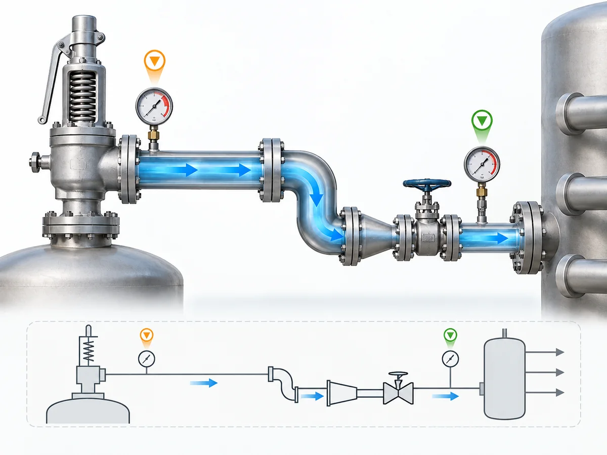
يحتاج حساب الضغط الخلفي المتراكم إلى حدود فيزيائية. تتبّع مسار التصريف من مخرج صمام الأمان إلى نقطة لاحقة يكون فيها ضغط النظام معروفًا أو يمكن تحديده من خلال تحليل النظام المعمول به.
قد تكون الجهة المستقبلة للتصريف الغلاف الجوي، أو مستقبلًا مغلقًا، أو نظام تهوية، أو خط تنفيس مشترك. المهم هو الضغط عند نهاية الحساب وكيفية تحديد ذلك الضغط.
ابدأ بحالة التنفيس المحددة
معدل التنفيس المطلوب للعملية ليس تلقائيًا معدل التدفق الصحيح لحساب أنابيب المخرج لكل جهاز تنفيس ضغط.
قد يعتمد أساس التدفق اللاحق على سلوك تشغيل الصمام وعلى طريقة حساب المقاسات أو التركيب المطبقة. لذلك قد تتطلب بعض الأجهزة ذات الفعل المباشر والتصاميم المعيارية التي تعمل بالبايلوت اعتبارًا مختلفًا عند تحديد التدفق المستخدم في حساب المسار اللاحق.
إذا لم يكن حمل التنفيس المطلوب نفسه قد حُدد بعد، فهذه مهمة حساب مقاسات في المرحلة السابقة. راجع دليل حساب مقاسات صمامات الأمان; ؛ تتناول هذه المقالة معدل التنفيس المناسب كمدخل بدلًا من إعادة حساب سيناريو الضغط الزائد بالكامل.
اجمع مدخلات المائع وظروف التنفيس
يجب أن تحدد حزمة الحسابات، حسب الاقتضاء:
- ما إذا كان التصريف سائلًا أو غازًا أو بخارًا؛;
- ضغط ودرجة حرارة التنفيس؛;
- خصائص المائع المطلوبة وفقًا لطريقة الحساب المختارة؛;
- أساس سعة التدفق المطلوبة أو الواجبة التطبيق؛;
- مساحة تدفق صمام الأمان وبيانات التصريف عندما تستخدمها الطريقة المختارة.
استخدم الخصائص المطابقة للظروف التي تتطلبها الطريقة المختارة بدلًا من استبدالها ببيانات تشغيل غير ذات صلة لمجرد توفرها في ورقة بيانات العملية.
ارسم مسار التصريف الفعلي
سجّل المسار الهيدروليكي وليس فقط مقاس المخرج الاسمي:
- الأقطار الداخلية الفعلية للأنابيب؛;
- الأطوال المستقيمة؛;
- الأكواع والوصلات الأخرى؛;
- الصمامات أو المقاومات؛;
- المخفضات والموسعات؛;
- كاتمات الصوت أو غيرها من المعدات downstream؛;
- تغيرات الارتفاع حيث تتطلبها الطريقة المختارة.
الحساب المعتمد فقط على طول الأنبوب المستقيم لن يمثل مسارًا مركبًا يحتوي على مقاومة موضعية كبيرة. تنتمي أسئلة التركيب الميكانيكي خارج هذه المهمة الهيدروليكية إلى دليل تركيب صمام الأمان.
حدد حدود الضغط في اتجاه المصب
أخيرًا، حدد Pu, أو ضغط المصب المكافئ المستخدم في الطريقة المختارة.
بالنسبة للتصريف إلى الغلاف الجوي، تختلف الحالة الطرفية عن صمام متصل بمجمع مغلق مضغوط. في المجمع المشترك، قد تعتمد الحدود أيضًا على مصادر تنفيس أخرى وحالة النظام قيد التحليل.
| مجموعة المدخلات | ما يجب تحديده | لماذا يغير الحساب |
|---|---|---|
| حالة التنفيس | أساس معدل التصريف المطبق | يحدد الحمل الداخل إلى نظام المخرج. |
| حالة المائع | سائل أو غاز/بخار أو ثنائي الطور محتمل | يحدد الطريقة الهيدروليكية المناسبة. |
| ظروف التنفيس | الضغط ودرجة الحرارة والخصائص المطلوبة | يحدد حالة المائع المستخدمة في الحساب. |
| بيانات الصمام | مساحة التدفق وبيانات التصريف المطبقة عند الحاجة | يدخل في حسابات المخرج وفق المعايير. |
| هندسة الأنابيب | القطر الداخلي الفعلي وأطوال المقاطع | يتحكم في مساحة التدفق والمقاومة الموزعة. |
| المكونات | الوصلات والصمامات والمخفضات والموسعات وغيرها من القيود | يضيف مقاومة موضعية. |
| الارتفاع | التغيرات الرأسية ذات الصلة | قد يسهم في توازن الضغط حسب الطريقة والمائع. |
| حالة الطرف النهائي | الضغط عند الضغط الجوي أو المستقبل أو المجمع أو أي عقدة أخرى في اتجاه المصب | يحدد الحدود الهيدروليكية. |
| حالة النظام المشترك | تدفقات تنفيس أخرى أو ضغط مجمع متغير عند الاقتضاء | قد يغير الضغط الذي يراه الفرع. |
قبل المتابعة، ينبغي أن يجيب أساس الحساب على أربعة أسئلة: ما التدفق الذي يتم تصريفه؟ ما حالة المائع المستخدمة؟ ما المسار الفيزيائي المشمول؟ ما الضغط الموجود عند نهاية ذلك المسار؟
كيفية حساب الضغط الخلفي المتراكم لحالة تنفيس سائل
لحالة محددة سائل أحادي الطور ، يقدم دليل الهندسة الخاص بـ LESER، بتطبيق طريقة خط المخرج وفق ISO 4126-9، علاقة بين مقاومة نظام التصريف والضغط عند مخرج الصمام:
(Pb − Pu) / (P0 − Pb) = ζA [KdrA / (0.9AA)]2
في هذه العلاقة المعروضة، P0, Pb و Pu هي ضغوط مطلقة ويجب استخدامها على أساس ضغط متسق. الفرق Pb − Pu هو مساهمة الضغط المتراكم فوق الحدود المصبّية المحددة في نموذج الحساب هذا.
حيث:
- P0 = relieving pressure, absolute;
- Pb = pressure at the valve outlet during discharge, absolute;
- Pu = pressure at the end of the calculated discharge path, absolute;
- A = safety-valve flow area;
- AA = flow area of the outlet pipe;
- Kdr = applicable derated discharge coefficient used by the method;
- ζA = resistance coefficient representing the downstream path.
The usefulness of the relation is not that it provides an isolated shortcut. It keeps valve flow geometry, outlet-pipe geometry, system resistance, relieving pressure and downstream pressure within one defined calculation model.
Establish the liquid-flow calculation basis
First confirm that the service can legitimately be treated by the selected سائل أحادي الطور method.
ISO 4126-9 states that its application and installation information assumes single-phase flow and routes two-phase conditions to ISO 4126-10. If the liquid can flash materially in the valve or outlet piping, changing the density inside this single-phase equation does not by itself establish a valid two-phase calculation.
Calculate straight-pipe and local resistance
The discharge resistance represented by ζA can include distributed pipe resistance and local component losses.
ζA = λL/D + Σζi
when that representation is consistent with the selected method.
- λL/D represents straight-pipe resistance;
- Σζi represents local resistance from fittings and components.
Use one internally consistent resistance representation. For example, if an elbow has already been converted into equivalent straight-pipe length, counting the same full elbow local-loss coefficient again would duplicate that resistance.
Include static-head effects where applicable
Elevation is a pressure-balance issue, especially in liquid discharge piping, but its treatment is method-dependent.
Some hydraulic methods explicitly include a hydrostatic contribution associated with elevation difference; others are formulated differently. Combining an equation from one method with a separate ρgΔz term from another therefore requires an established technical basis rather than an intuitive addition.
Build the pressure-loss calculation from outlet to boundary
For calculation convenience, define:
R = ζA [KdrA / (0.9AA)]2
The same verified relation can then be rearranged algebraically:
Pb = (Pu + RP0) / (1 + R)
and the built-up component is:
ΔPbuilt-up = Pb − Pu
Pu remains the downstream boundary condition; Pb − Pu is the generated built-up component in this calculation model.
Worked single-phase liquid calculation structure
- Record absolute P0 و Pu on a consistent pressure basis.
- Record valve flow area A and actual discharge-pipe area AA.
- Establish the applicable Kdr.
- Calculate the complete downstream resistance coefficient ζA.
- Calculate R.
- Solve for absolute Pb.
- Calculate Pb − Pu as the built-up component.
- Carry the result into valve/system acceptance review instead of comparing it with an assumed universal percentage.
How to Calculate Built-Up Back Pressure for Gas or Vapor Relief
Gas and vapor discharge need a different calculation approach because density does not remain effectively constant as pressure changes through the discharge system.
A constant-density liquid-style pressure-drop treatment is therefore not automatically valid for a safety-valve gas or vapor discharge.
Why gas or vapor cannot be treated like an incompressible liquid
As gas pressure falls through the outlet system, density and velocity change together. Pressure ratios and thermodynamic properties can become important, and a critical-flow condition can develop within the discharge path.
The need for a separate method comes from this coupling between pressure, density and velocity, rather than simply from the lower density of a gas.
Account for changing pressure, density and flow conditions
Depending on the selected compressible-flow method, relevant inputs can include:
- relieving pressure;
- downstream pressure;
- درجة حرارة التنفيس;
- ratio of specific heats k;
- compressibility or other real-gas information required by the method;
- safety-valve flow area;
- outlet-pipe flow area;
- applicable discharge coefficient;
- total piping resistance.
The properties and pressure basis should come from one selected compressible-flow method rather than from a mixture of unrelated gas-flow equations.
Check whether critical or choked-flow behavior changes the method
LESER’s Engineering manual, applying the ISO 4126-9 outlet-line method, includes a check for a possible second critical-flow condition at the outlet-pipe end:
Pc/P0 = [2/(k + 1)]k/(k − 1) × KdrA/(0.9AA)
This equation checks the potential critical condition at the pipe outlet; it does not by itself calculate the complete valve-outlet back pressure Pb. The pressure quantities used in this critical-pressure relationship are evaluated on the required absolute-pressure basis.
Solve the discharge path to the defined downstream condition
- Establish the applicable discharge-flow basis.
- Define relieving and downstream pressures on the pressure basis required by the selected method.
- Obtain the fluid properties required by the selected compressible-flow model.
- Calculate resistance through the actual outlet path.
- Evaluate the applicable critical outlet condition.
- Solve the selected compressible-flow relationship for the discharge system.
- Revise piping geometry and recalculate if the resulting condition is unacceptable.
For a complicated compressible system, a validated engineering calculation package or hydraulic model may be more appropriate than a compact hand equation. Software still depends on correctly defined boundary conditions, fluid state and relief-case assumptions.
How Fittings, Elevation and a Closed or Common Header Affect the Calculation
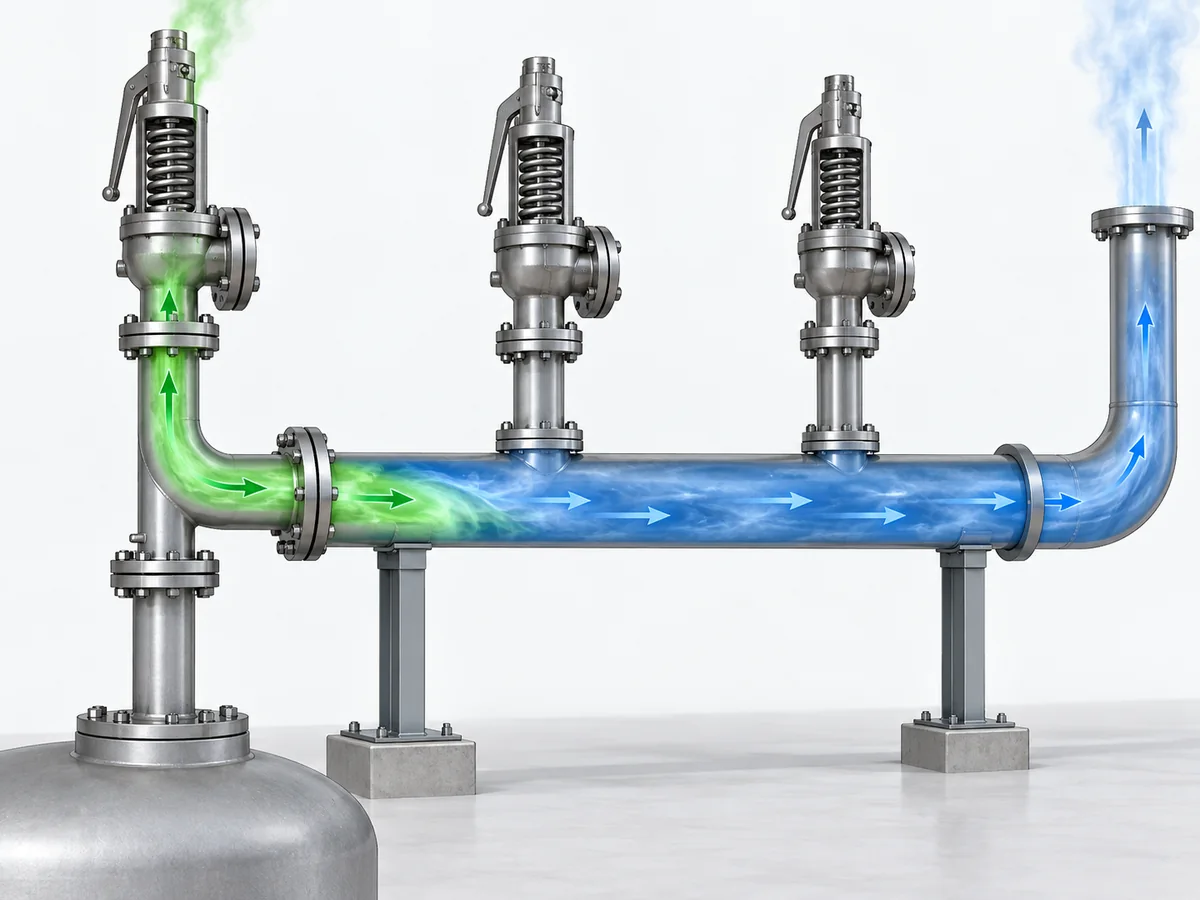
A real safety-valve discharge system rarely consists of one constant-diameter straight pipe to atmosphere. The calculation needs to represent the actual hydraulic path while keeping different pressure contributions conceptually separate.
| Discharge-system feature | How it affects the calculation |
|---|---|
| Straight pipe | Adds distributed resistance. |
| Elbows, valves and fittings | Add local resistance. |
| Reducers and expanders | Change geometry and local hydraulic behavior. |
| الارتفاع | Can modify pressure balance according to fluid and calculation method. |
| Pressurized receiver/header | Sets or influences the downstream boundary pressure. |
| Other relief devices | Can change the pressure in a shared network. |
Include elbows, valves and diameter changes without double counting
Choose one consistent way of representing local resistance.
If a fitting is represented using a local loss coefficient, include that coefficient once. If the selected method converts the fitting into equivalent pipe length, adding the same full local-loss contribution again would overstate the resistance.
Treat elevation according to the applicable fluid calculation
Elevation is a pressure-balance contribution rather than friction.
For liquid systems, hydrostatic head can materially affect the pressure balance. For gas/vapor systems, the appropriate treatment depends on the selected compressible-flow method and properties.
The elevation contribution should therefore follow the selected hydraulic method rather than being appended from an incompatible formula.
Separate downstream/header pressure from the pressure generated by this discharge
Before the subject valve opens:
existing downstream/header pressure → superimposed component
After the subject valve begins relieving:
additional pressure produced by its flow through downstream resistance → built-up component
If other pressure-relief devices discharge into the same network, the pressure seen at the branch connection can change again. In that situation, the additional system interaction needs to be represented rather than hidden inside a fixed downstream-pressure assumption.
Check whether other relief flows can change the system boundary
For the relevant relief scenario, ask:
- Can multiple devices relieve during the same credible event?
- Does their combined flow change the header pressure seen by this valve?
- Can the downstream pressure still be represented by one defensible fixed boundary?
- Or does the problem require a system-level hydraulic calculation?
Once the downstream pressure depends materially on an interacting relief network, a single isolated tailpipe calculation may no longer represent the installed system. The broader relief/disposal-system task belongs in ZOBAI’s دليل أنظمة تنفيس الضغط API 521.
How to Interpret the Calculated Back Pressure
A calculated built-up back pressure is a hydraulic result. It is not, by itself, an allowable back-pressure limit or proof that a particular safety valve is suitable.
Calculated built-up back pressure is not an allowable limit
The calculation answers:
What outlet-side pressure does the defined discharge system generate under the stated assumptions?
The acceptance check answers a different question:
How much back pressure may this particular valve and project accept under the applicable basis?
The second answer can depend on the applicable standard or code, exact valve architecture, manufacturer documentation, service condition and project specification.
Compare the result with the applicable valve and project basis
Determine whether the relevant acceptance check uses:
- built-up back pressure alone;
- الضغط الخلفي المتراكب؛;
- combined outlet back pressure;
- minimum and maximum variable back pressure;
- a manufacturer-defined capacity correction or other design-specific limit.
A conventional spring-loaded valve, balanced bellows valve and pilot-operated valve should not be reduced to a universal percentage table. Their acceptable behavior is design- and service-dependent.
For the broader valve-configuration decision after the hydraulic condition is known, use ZOBAI’s دليل الضغط الخلفي والمنفاخ.
Revisit discharge-pipe sizing when the result is unacceptable
Outlet piping and valve review form an iterative engineering process. If the calculated condition is unacceptable, first examine whether downstream resistance can reasonably be reduced before turning the result into a valve-type selection rule.
Possible review points include:
- increasing discharge-pipe flow area where technically appropriate;
- reducing unnecessary restrictions;
- simplifying routing;
- reviewing high-loss fittings or silencers;
- reassessing the shared-system boundary condition.
After a material hydraulic change, repeat the calculation. If piping changes cannot produce an acceptable condition, assess the valve configuration using exact manufacturer and project evidence.
What information should move into the engineering review or RFQ
A technically useful engineering or supplier review should identify, as applicable:
- وظيفة التنفيس المطلوبة — the protected-system demand;
- outlet calculation flow basis — the flow used for downstream hydraulic checking;
- fluid and phase — liquid, gas/vapor or potentially two-phase;
- relieving pressure and temperature;
- calculated built-up back pressure;
- superimposed back-pressure range;
- whether downstream pressure is constant or variable;
- discharge destination and header arrangement;
- applicable project code or standard;
- candidate valve/configuration data when already defined.
The hydraulic calculation prepares a product-specific engineering question. It does not establish a ZOBAI model limit or product suitability that has not been confirmed by the relevant product documentation.
When a Simple Built-Up Back-Pressure Calculation Is Not Enough
The calculation workflow above is deliberately bounded. It applies only while the assumptions behind the selected single-phase hydraulic method remain defensible.
Flashing or two-phase relief
ISO 4126-9 states that its application and installation information assumes single-phase flow. Gas/liquid two-phase relief requires a different calculation treatment; ISO 4126-10:2024 is one current authoritative reference specifically addressing two-phase safety-device sizing.
If a liquid can flash materially in the valve or outlet piping, or if the relieving stream is already two-phase, a single-phase liquid equation with a substituted density is not enough unless the applicable method explicitly supports that treatment.
The governing project method still has to be established. Referencing an ISO document does not make it the mandatory legal basis for every jurisdiction or project.
Interacting relief devices and complex common headers
A branch-level calculation also becomes insufficient when its downstream pressure is controlled by interacting relief flows.
Escalation is appropriate when:
- several pressure-relief devices may relieve during the applicable scenario;
- their flows materially alter shared-header pressure;
- the terminal disposal system controls the branch condition;
- pressure varies enough that a fixed downstream boundary is not defensible;
- the model requires hydraulic interaction between several relieving sources.
Cases where the hydraulic assumptions are no longer defensible
The selected method should be reassessed if:
- the fluid phase is uncertain;
- significant flashing is possible;
- required thermodynamic properties are unavailable;
- a critical-flow condition cannot be represented by the selected model;
- the downstream pressure cannot be established for the relevant case;
- the result materially depends on an assumption that has not been technically justified.
Missing engineering information should remain visible as an unresolved input rather than being replaced by an optimistic assumption simply so the calculation can continue.
Escalate to a more appropriate system-level analysis
Built-up back-pressure calculation can proceed when:
defined single-phase case + defensible flow basis + known discharge path + defined downstream condition
Use a more appropriate specialist or system-level analysis when:
two-phase/flashing behavior + interacting common-header hydraulics + unresolved critical assumptions
A built-up back-pressure calculation is most useful when its boundary is explicit. Its role is to produce a defined hydraulic result that can be handed to the valve, piping and project review—not to claim that the entire pressure-relief system has been proven acceptable.