了解如何计算安全阀排放管道中的积聚背压,确定水力边界,处理液体与气体流动,并验证计算结果。.

积聚背压是指安全阀出口处因泄放介质流经下游排放系统而产生的那部分压力。. 它与阀门开启前密闭排放总管中已存在的压力不同。ISO 术语将这种预先存在的压力单独定义为 叠加背压.
因此,可靠的背压积聚计算包含四个部分:明确压力分量与计算边界、确定正确的泄放流量基准、选用与流体状态相适应的水力计算方法,然后将计算结果与适用的阀门数据及项目验收依据进行对比。.
计算背压与判断安全阀能否承受该背压是两项独立的工程工作。背压表现取决于阀门设计和使用工况,因此不应以经验表格中照搬的通用百分比替代适用的阀门数据和项目依据。.
您实际计算的是哪种积聚背压?
在计算管道摩擦阻力之前,先确认您所处理的是哪一种出口侧压力。.
积聚背压、叠加背压和总背压是不同的压力量
| 压力量 | 工程含义 |
|---|---|
| 积聚背压 | 安全阀出口处因介质流经阀门和排放系统而产生的压力。. |
| 叠加背压 | 当安全阀需要动作时,由下游系统其他来源引起的、存在于阀门出口处的压力。. |
| 泄放期间的背压 | 由相关叠加背压和积聚背压分量共同形成的出口压力。. |
ISO 4126 术语以叠加背压和积聚背压分量来定义背压,并指出积聚背压分量是由介质流经阀门及排放系统所产生的压力。.
当安全阀向封闭排放总管或共用排放总管排放时,这一区分尤为重要。若该总管在目标安全阀开启前已存在压力,则该压力并非由目标泄放流量产生。.
进行水力计算前先确定基准点
本指南采用的基于 ISO 4126-9 的出口管线计算路径中:
- Pb 为泄放期间安全阀出口处的压力;;
- Pu 为所计算排放路径下游端的压力;;
- Pb − Pu 在本计算模型中表示该下游边界以上产生的压力增量。.
如果没有这个参考边界,压降计算可能在算术上正确,但描述的却是错误的压力分量。.
确定排放管道计算边界与所需输入参数
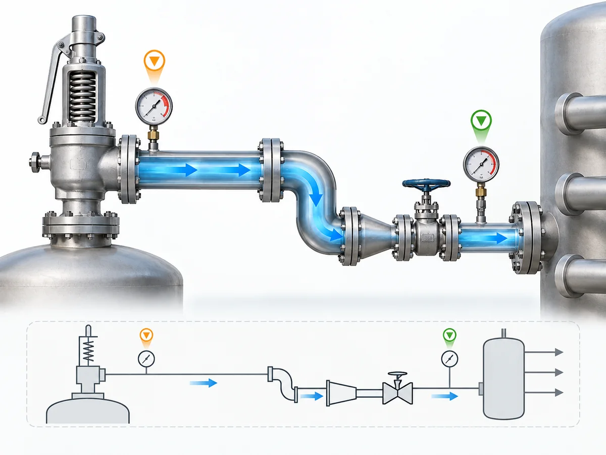
背压积聚计算需要明确的物理边界。从安全阀出口开始追踪排放路径,直至下游压力条件已知或可通过适用系统分析确定的某一点。.
终点可能是大气、密闭接收容器、放空系统或共用泄放总管。关键在于 计算终点处的压力以及该压力是如何确定的.
从已确定的泄放工况开始
所需工艺泄放量并不自动等同于每台压力泄放装置正确的出口管道计算流量。.
下游流量基准可能取决于阀门运行特性以及所采用的定径或安装方法。因此,某些直接作用式装置和调节型先导式结构在确定下游计算所用流量时,可能需要不同的考虑。.
如果所需泄放负荷本身尚未确定,那属于上游定径工作。参见 安全阀定径指南; ;本文将适当的泄放流量作为输入条件,而非重新计算整个超压工况。.
收集流体和泄放条件输入参数
计算文件应视情况明确以下内容:
- 泄放介质为液体、气体还是蒸汽;;
- 泄放压力和温度;;
- 所选计算方法所需的流体物性;;
- 所需或适用的流动排量基准;;
- 所选方法使用安全阀流通面积和排放数据时的相关数据。.
应使用与所选方法要求工况相对应的物性参数,而不是仅因工艺数据表上恰好有无关的运行数据就将其替代使用。.
确定实际泄放路径
记录实际水力路径,而不仅仅是公称出口尺寸:
- 实际管道内径;;
- 直管段长度;;
- 弯头及其他管件;;
- 阀门或节流件;;
- 异径管和扩径管;;
- 消音器或其他下游设备;;
- 所选计算方法要求时的高程变化。.
仅基于直管段长度进行的计算无法代表含有显著局部阻力的实际安装路径。超出本水力计算范围的机械安装问题请参见 安全阀安装指南.
确定下游压力边界
最后,确定 Pu, 或所选计算方法采用的等效下游压力。.
对于大气排放,其终端条件与接入带压封闭排放总管的安全阀不同。在共用排放总管中,边界条件还可能取决于其他泄放源以及所分析的系统工况。.
| 输入分组 | 需确定的内容 | 为何会改变计算 |
|---|---|---|
| 泄放工况 | 适用的泄放流量基准 | 确定进入排放系统的负荷。. |
| 流体状态 | 液体、气体/蒸汽或可能为两相 | 确定适用的水力计算方法。. |
| 泄放条件 | 压力、温度及所需物性参数 | 确定计算所采用的流体状态。. |
| 阀门数据 | 需要时的流通面积及适用排量数据 | 纳入基于标准的出口计算。. |
| 管道几何参数 | 实际内径与各管段长度 | 决定流通面积与沿程阻力。. |
| 组成部件 | 管件、阀门、异径管、扩径管及其他阻力件 | 增加局部阻力。. |
| 标高 | 相关垂直高差 | 根据计算方法和流体,可能影响压力平衡。. |
| 终端工况 | 大气压、接收器、集管或其他下游节点处的压力 | 确定水力边界。. |
| 共用系统状态 | 适用时的其他泄放流量或变化的集管压力 | 可能改变该支路所承受的压力。. |
在继续之前,计算依据应回答四个问题: 排放的是什么流量?采用的是什么流体状态?包含的是哪条物理路径?该路径末端存在什么压力?
如何计算液体泄放工况下的积聚背压
对于确定的 单相液体 工况,LESER 工程手册采用 ISO 4126-9 出口管线方法,给出了排放系统阻力与安全阀出口压力之间的关系:
(Pb − Pu) / (P0 − Pb) = ζA [KdrA / (0.9AA)]2
对于本显示关系式,P0, Pb 和 Pu 均为绝对压力,必须采用一致的绝对压力基准。. 差值 Pb − Pu 为本计算模型中超过规定下游边界的积聚压力贡献。.
其中:
- P0 = 泄放压力,绝对压力;;
- Pb = 排放期间阀出口处的压力,绝对压力;;
- Pu = 计算排放路径末端处的压力,绝对压力;;
- A = 安全阀流通面积;;
- AA = 出口管道流通面积;;
- Kdr = 该方法采用的经降额排量系数;;
- ζA = 表示下游管路阻力的阻力系数。.
该关系的实用价值不在于提供一个孤立的快捷算法,而是将阀门流通几何、出口管道几何、系统阻力、泄放压力和下游压力纳入同一个明确的计算模型。.
建立液体流动计算基础
首先确认该工况可合理地采用所选 单相液体 方法进行计算。.
ISO 4126-9 指出,其应用与安装资料假定为单相流,并将两相工况引至 ISO 4126-10。若液体在阀门或出口管道内可能发生显著闪蒸,仅在本单相方程中改变密度并不能自行建立有效的两相计算。.
计算直管阻力和局部阻力
由 ζ 表示的排放阻力A 可包含沿程管道阻力和局部部件损失。.
ζA = λL/D + Σζi
when that representation is consistent with the selected method.
- λL/D represents straight-pipe resistance;
- Σζi represents local resistance from fittings and components.
Use one internally consistent resistance representation. For example, if an elbow has already been converted into equivalent straight-pipe length, counting the same full elbow local-loss coefficient again would duplicate that resistance.
Include static-head effects where applicable
Elevation is a pressure-balance issue, especially in liquid discharge piping, but its treatment is method-dependent.
Some hydraulic methods explicitly include a hydrostatic contribution associated with elevation difference; others are formulated differently. Combining an equation from one method with a separate ρgΔz term from another therefore requires an established technical basis rather than an intuitive addition.
Build the pressure-loss calculation from outlet to boundary
For calculation convenience, define:
R = ζA [KdrA / (0.9AA)]2
The same verified relation can then be rearranged algebraically:
Pb = (Pu + RP0) / (1 + R)
and the built-up component is:
ΔPbuilt-up = Pb − Pu
Pu remains the downstream boundary condition; Pb − Pu is the generated built-up component in this calculation model.
Worked single-phase liquid calculation structure
- Record absolute P0 和 Pu on a consistent pressure basis.
- Record valve flow area A and actual discharge-pipe area AA.
- Establish the applicable Kdr.
- Calculate the complete downstream resistance coefficient ζA.
- Calculate R.
- Solve for absolute Pb.
- Calculate Pb − Pu as the built-up component.
- Carry the result into valve/system acceptance review instead of comparing it with an assumed universal percentage.
How to Calculate Built-Up Back Pressure for Gas or Vapor Relief
Gas and vapor discharge need a different calculation approach because density does not remain effectively constant as pressure changes through the discharge system.
A constant-density liquid-style pressure-drop treatment is therefore not automatically valid for a safety-valve gas or vapor discharge.
Why gas or vapor cannot be treated like an incompressible liquid
As gas pressure falls through the outlet system, density and velocity change together. Pressure ratios and thermodynamic properties can become important, and a critical-flow condition can develop within the discharge path.
The need for a separate method comes from this coupling between pressure, density and velocity, rather than simply from the lower density of a gas.
Account for changing pressure, density and flow conditions
Depending on the selected compressible-flow method, relevant inputs can include:
- relieving pressure;
- downstream pressure;
- 泄放温度;;
- ratio of specific heats k;
- compressibility or other real-gas information required by the method;
- safety-valve flow area;
- outlet-pipe flow area;
- applicable discharge coefficient;
- total piping resistance.
The properties and pressure basis should come from one selected compressible-flow method rather than from a mixture of unrelated gas-flow equations.
Check whether critical or choked-flow behavior changes the method
LESER’s Engineering manual, applying the ISO 4126-9 outlet-line method, includes a check for a possible second critical-flow condition at the outlet-pipe end:
Pc/P0 = [2/(k + 1)]k/(k − 1) × KdrA/(0.9AA)
This equation checks the potential critical condition at the pipe outlet; it does not by itself calculate the complete valve-outlet back pressure Pb. The pressure quantities used in this critical-pressure relationship are evaluated on the required absolute-pressure basis.
Solve the discharge path to the defined downstream condition
- Establish the applicable discharge-flow basis.
- Define relieving and downstream pressures on the pressure basis required by the selected method.
- Obtain the fluid properties required by the selected compressible-flow model.
- Calculate resistance through the actual outlet path.
- Evaluate the applicable critical outlet condition.
- Solve the selected compressible-flow relationship for the discharge system.
- Revise piping geometry and recalculate if the resulting condition is unacceptable.
For a complicated compressible system, a validated engineering calculation package or hydraulic model may be more appropriate than a compact hand equation. Software still depends on correctly defined boundary conditions, fluid state and relief-case assumptions.
How Fittings, Elevation and a Closed or Common Header Affect the Calculation
A real safety-valve discharge system rarely consists of one constant-diameter straight pipe to atmosphere. The calculation needs to represent the actual hydraulic path while keeping different pressure contributions conceptually separate.
| Discharge-system feature | How it affects the calculation |
|---|---|
| Straight pipe | Adds distributed resistance. |
| Elbows, valves and fittings | Add local resistance. |
| Reducers and expanders | Change geometry and local hydraulic behavior. |
| 标高 | Can modify pressure balance according to fluid and calculation method. |
| Pressurized receiver/header | Sets or influences the downstream boundary pressure. |
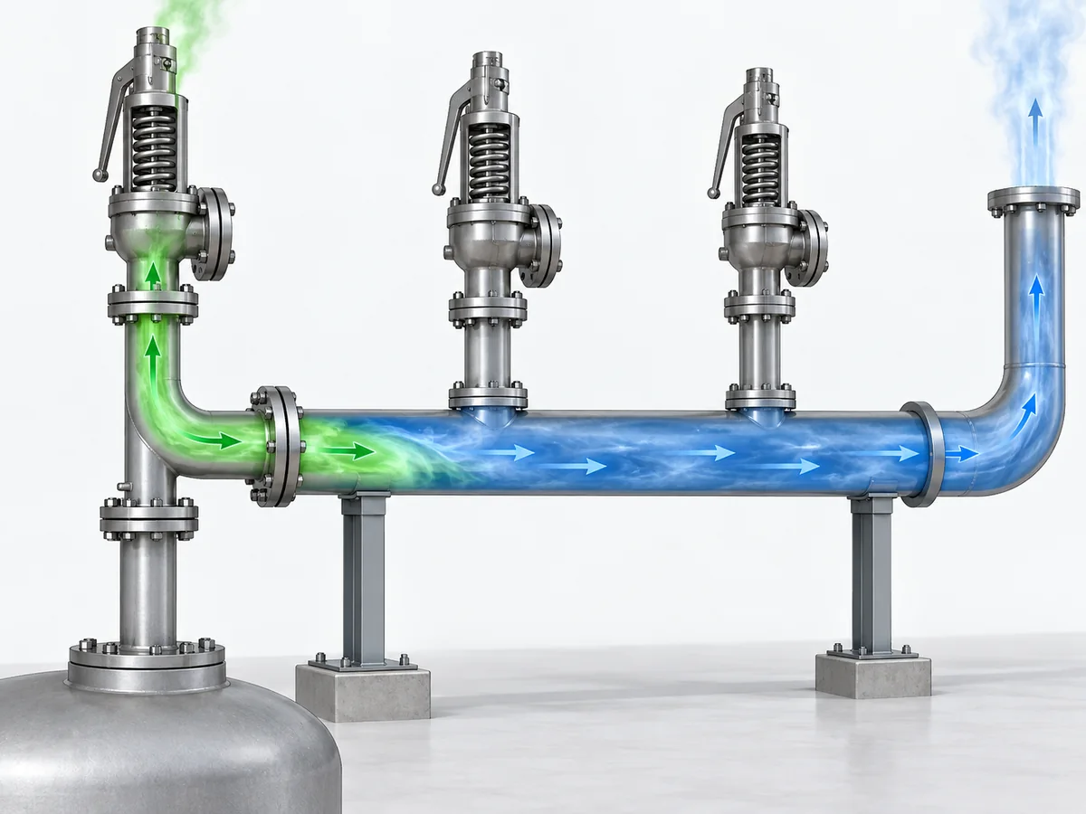
| Other relief devices | Can change the pressure in a shared network. |
Include elbows, valves and diameter changes without double counting
Choose one consistent way of representing local resistance.
If a fitting is represented using a local loss coefficient, include that coefficient once. If the selected method converts the fitting into equivalent pipe length, adding the same full local-loss contribution again would overstate the resistance.
Treat elevation according to the applicable fluid calculation
Elevation is a pressure-balance contribution rather than friction.
For liquid systems, hydrostatic head can materially affect the pressure balance. For gas/vapor systems, the appropriate treatment depends on the selected compressible-flow method and properties.
The elevation contribution should therefore follow the selected hydraulic method rather than being appended from an incompatible formula.
Separate downstream/header pressure from the pressure generated by this discharge
Before the subject valve opens:
existing downstream/header pressure → superimposed component
After the subject valve begins relieving:
additional pressure produced by its flow through downstream resistance → built-up component
If other pressure-relief devices discharge into the same network, the pressure seen at the branch connection can change again. In that situation, the additional system interaction needs to be represented rather than hidden inside a fixed downstream-pressure assumption.
Check whether other relief flows can change the system boundary
For the relevant relief scenario, ask:
- Can multiple devices relieve during the same credible event?
- Does their combined flow change the header pressure seen by this valve?
- Can the downstream pressure still be represented by one defensible fixed boundary?
- Or does the problem require a system-level hydraulic calculation?
Once the downstream pressure depends materially on an interacting relief network, a single isolated tailpipe calculation may no longer represent the installed system. The broader relief/disposal-system task belongs in ZOBAI’s API 521 Pressure Relief Systems Guide.
How to Interpret the Calculated Back Pressure
A calculated built-up back pressure is a hydraulic result. It is not, by itself, an allowable back-pressure limit or proof that a particular safety valve is suitable.
Calculated built-up back pressure is not an allowable limit
The calculation answers:
What outlet-side pressure does the defined discharge system generate under the stated assumptions?
The acceptance check answers a different question:
How much back pressure may this particular valve and project accept under the applicable basis?
The second answer can depend on the applicable standard or code, exact valve architecture, manufacturer documentation, service condition and project specification.
Compare the result with the applicable valve and project basis
Determine whether the relevant acceptance check uses:
- built-up back pressure alone;
- superimposed back pressure;
- combined outlet back pressure;
- minimum and maximum variable back pressure;
- a manufacturer-defined capacity correction or other design-specific limit.
A conventional spring-loaded valve, balanced bellows valve and pilot-operated valve should not be reduced to a universal percentage table. Their acceptable behavior is design- and service-dependent.
For the broader valve-configuration decision after the hydraulic condition is known, use ZOBAI’s 背压与波纹管指南.
Revisit discharge-pipe sizing when the result is unacceptable
Outlet piping and valve review form an iterative engineering process. If the calculated condition is unacceptable, first examine whether downstream resistance can reasonably be reduced before turning the result into a valve-type selection rule.
Possible review points include:
- increasing discharge-pipe flow area where technically appropriate;
- reducing unnecessary restrictions;
- simplifying routing;
- reviewing high-loss fittings or silencers;
- reassessing the shared-system boundary condition.
After a material hydraulic change, repeat the calculation. If piping changes cannot produce an acceptable condition, assess the valve configuration using exact manufacturer and project evidence.
What information should move into the engineering review or RFQ
A technically useful engineering or supplier review should identify, as applicable:
- required relief duty — the protected-system demand;
- outlet calculation flow basis — the flow used for downstream hydraulic checking;
- fluid and phase — liquid, gas/vapor or potentially two-phase;
- relieving pressure and temperature;
- calculated built-up back pressure;
- superimposed back-pressure range;
- whether downstream pressure is constant or variable;
- discharge destination and header arrangement;
- applicable project code or standard;
- candidate valve/configuration data when already defined.
The hydraulic calculation prepares a product-specific engineering question. It does not establish a ZOBAI model limit or product suitability that has not been confirmed by the relevant product documentation.
When a Simple Built-Up Back-Pressure Calculation Is Not Enough
The calculation workflow above is deliberately bounded. It applies only while the assumptions behind the selected single-phase hydraulic method remain defensible.
Flashing or two-phase relief
ISO 4126-9 states that its application and installation information assumes single-phase flow. Gas/liquid two-phase relief requires a different calculation treatment; ISO 4126-10:2024 is one current authoritative reference specifically addressing two-phase safety-device sizing.
If a liquid can flash materially in the valve or outlet piping, or if the relieving stream is already two-phase, a single-phase liquid equation with a substituted density is not enough unless the applicable method explicitly supports that treatment.
The governing project method still has to be established. Referencing an ISO document does not make it the mandatory legal basis for every jurisdiction or project.
Interacting relief devices and complex common headers
A branch-level calculation also becomes insufficient when its downstream pressure is controlled by interacting relief flows.
Escalation is appropriate when:
- several pressure-relief devices may relieve during the applicable scenario;
- their flows materially alter shared-header pressure;
- the terminal disposal system controls the branch condition;
- pressure varies enough that a fixed downstream boundary is not defensible;
- the model requires hydraulic interaction between several relieving sources.
Cases where the hydraulic assumptions are no longer defensible
The selected method should be reassessed if:
- the fluid phase is uncertain;
- significant flashing is possible;
- required thermodynamic properties are unavailable;
- a critical-flow condition cannot be represented by the selected model;
- the downstream pressure cannot be established for the relevant case;
- the result materially depends on an assumption that has not been technically justified.
Missing engineering information should remain visible as an unresolved input rather than being replaced by an optimistic assumption simply so the calculation can continue.
Escalate to a more appropriate system-level analysis
Built-up back-pressure calculation can proceed when:
defined single-phase case + defensible flow basis + known discharge path + defined downstream condition
Use a more appropriate specialist or system-level analysis when:
two-phase/flashing behavior + interacting common-header hydraulics + unresolved critical assumptions
A built-up back-pressure calculation is most useful when its boundary is explicit. Its role is to produce a defined hydraulic result that can be handed to the valve, piping and project review—not to claim that the entire pressure-relief system has been proven acceptable.