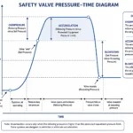
Back pressure can change how a safety valve opens, reaches lift, discharges, blows down and reseats, even when the valve passed a workshop set-pressure test. It may already exist at the outlet before opening, or it may develop after relief flow enters the discharge piping. The effect is not limited to a simple set-pressure shift: …
Back pressure can change how a safety valve opens, reaches lift, discharges, blows down and reseats, even when the valve passed a workshop set-pressure test. It may already exist at the outlet before opening, or it may develop after relief flow enters the discharge piping. The effect is not limited to a simple set-pressure shift: depending on valve design, outlet pressure can alter force balance, available lift, effective relieving capacity, chatter risk, blowdown, seat tightness and post-lift leakage.
The same principle applies to safety valves, safety relief valves and other reclosing pressure-relief valves, but the equipment tag alone does not establish the response. A conventional direct spring-loaded valve, a balanced bellows valve and a pilot-operated safety valve use different pressure areas and control arrangements. Their allowable superimposed and built-up back pressure must therefore be checked against the specific model, certified data, fluid, relieving conditions and outlet system.
60-Second Safety Valve Back Pressure Review
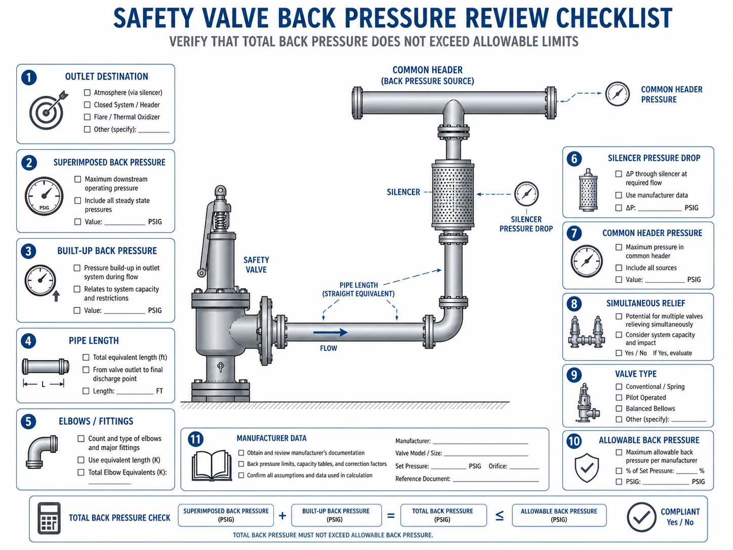
Before approving a new valve, a replacement, a silencer or a discharge-header modification, confirm the following information. If the required relieving flow, pressure range or downstream scenario is unknown, the installed valve response has not been adequately established.
What Is Back Pressure in a Safety Valve?
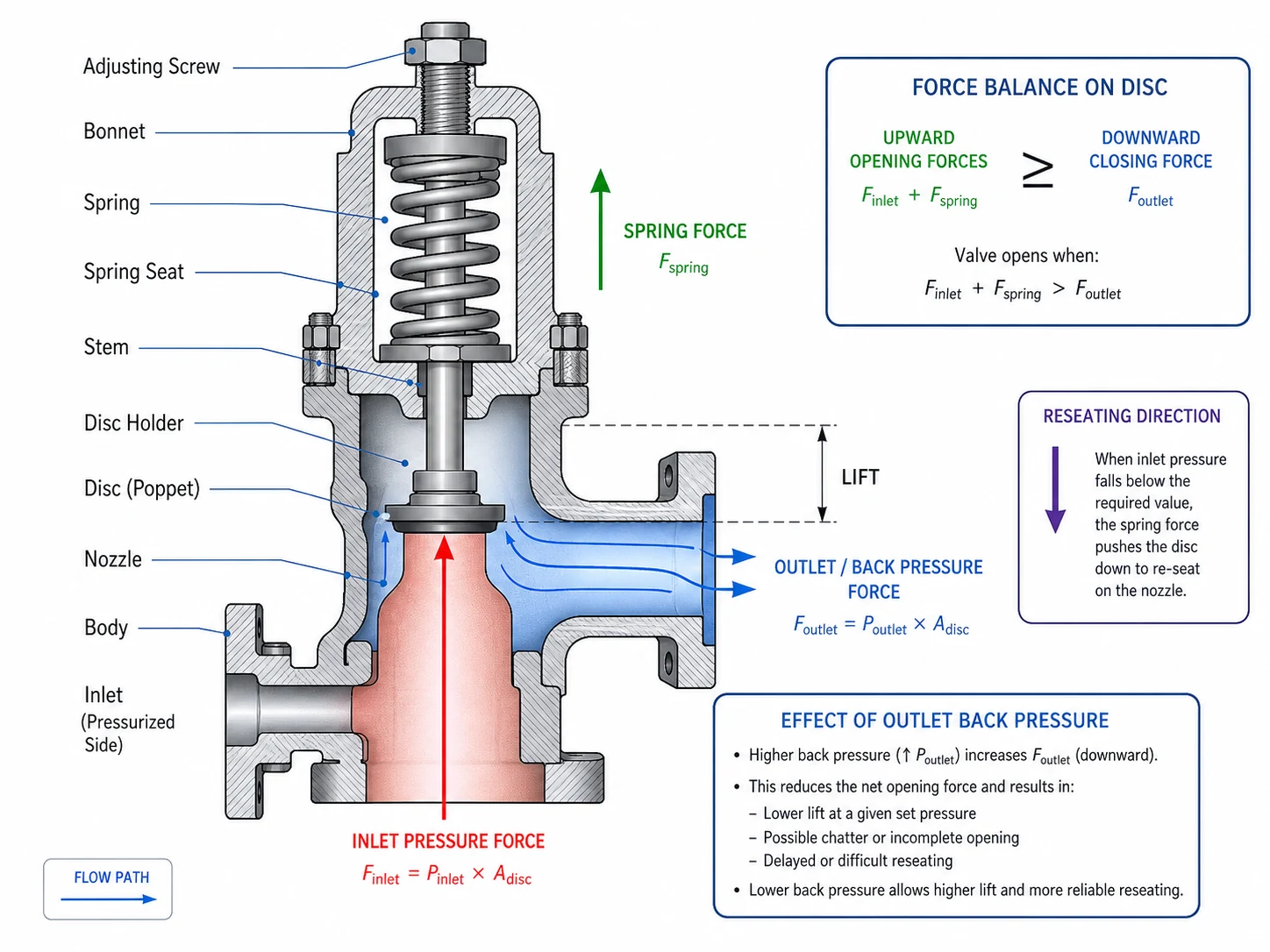
Back pressure is pressure acting at the outlet of a pressure-relief valve. It can exist while the valve is closed, and it can increase after the valve opens. Depending on the valve’s internal pressure areas and control method, that outlet pressure may influence the forces acting on the disc, bellows, piston, dome, pilot or spring chamber.
Back pressure must be distinguished from the other pressures used in safety-valve engineering:
Inlet Pressure
Pressure at the valve inlet from the protected equipment. It provides the opening force and can differ from vessel pressure when the inlet piping has pressure loss.
Set Pressure
The inlet pressure at which the valve is adjusted to demonstrate its specified opening characteristic under the approved test basis.
Relieving Pressure
The pressure condition used to determine or verify relieving capacity during the governing overpressure event.
Back Pressure
Outlet-side pressure that can influence set response, lift, capacity, blowdown, closing force and reseating, depending on valve construction.
Typical back-pressure sources include flare and vent headers, recovery systems, scrubbers, knockout drums, long tailpipes, silencers, elevated discharge stacks, downstream process pressure, condensate head, fouling, partial blockage and other relief devices connected to the same network.
Set pressure, overpressure, accumulation and blowdown must also remain distinct. Set pressure determines the specified opening-response point; overpressure is referenced to set pressure; accumulation is referenced to the protected equipment limit; blowdown is the difference between set and reseating pressure. Back pressure can interact with all of these behaviours but is not interchangeable with any of them. See 安全阀整定压力、超压与启闭压差.
Superimposed Back Pressure vs Built-Up Back Pressure
Superimposed Back Pressure
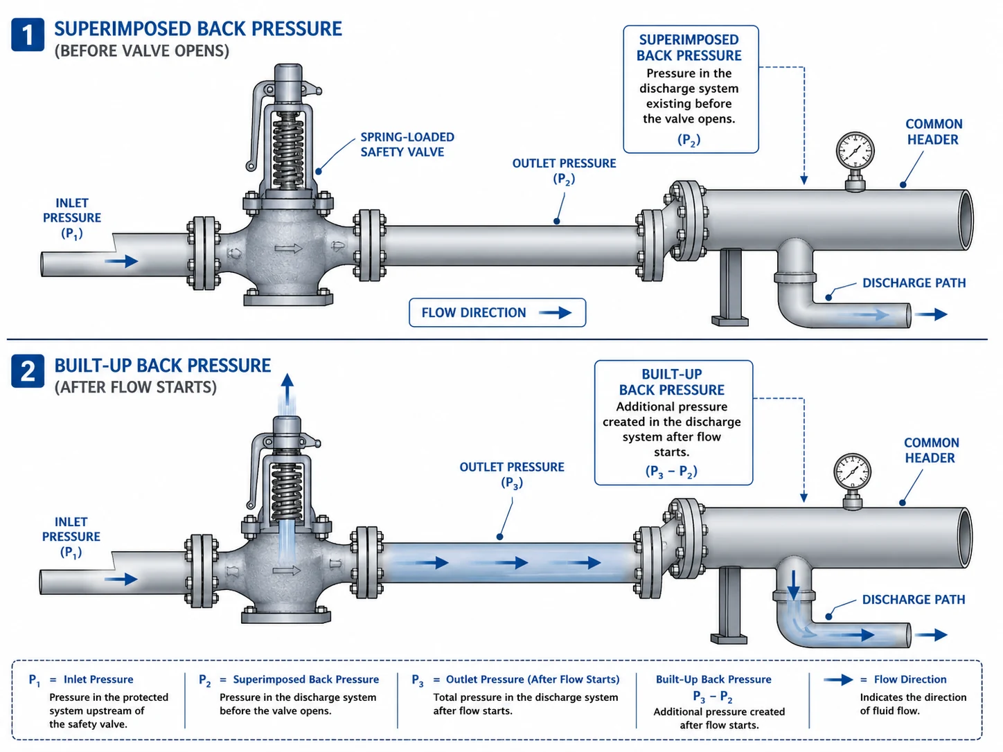
Superimposed back pressure is pressure present at the valve outlet before the valve opens. It may be constant, such as a stable downstream vessel pressure, or variable, such as a flare-header pressure that changes with plant operation, purge rate, another relief event or compressor loading.
Constant and variable describe the behaviour of the superimposed component; they are not separate categories from superimposed back pressure. This distinction matters because a stable, defined outlet pressure may be addressed through a model-specific calibration or cold differential test pressure procedure, while variable pressure cannot normally be represented by one fixed correction.
Common sources include:
- a pressurized flare, vent or recovery header;
- a downstream separator, scrubber or closed disposal vessel;
- another process system maintaining outlet pressure;
- other relief devices discharging into the same network;
- hydrostatic head from retained liquid or condensate;
- purge, blanketing or compressor pressure in the disposal system.
Built-Up Back Pressure
Built-up back pressure is generated after the valve opens because relieving flow encounters resistance in the outlet system. It is a hydraulic result of the governing flow case rather than a fixed valve property.
Built-up back pressure depends on:
- required relieving capacity and actual fluid properties;
- gas, steam, liquid, flashing or two-phase flow behaviour;
- outlet diameter, length, elevation, roughness and fittings;
- reducers, branch junctions, silencers and mufflers;
- scrubber, knockout drum, flare tip or recovery-equipment pressure loss;
- credible simultaneous relief from other devices;
- condensate, corrosion products, deposits or partial obstruction;
- transient and acoustic effects where the system is dynamically sensitive.
| Review Item | Superimposed Back Pressure | Built-Up Back Pressure |
|---|---|---|
| When it exists | Before the valve opens | After relieving flow begins |
| Primary source | Existing downstream or header pressure | Flow resistance in the discharge system |
| Typical behaviour | Constant, variable, pulsating or transient | Changes with flow, fluid state and network condition |
| Main valve concern | Opening force balance, repeatability and test correction | Lift, effective capacity, chatter, reaction and reseating |
| How it is established | Operating and relief-network pressure cases before opening | Hydraulic calculation at the applicable relieving flow |
| Common error | Using one average value for a variable header | Calculating at normal flow instead of the governing relief load |
Total Back Pressure and the Required Calculation Basis
Total back pressure is the outlet pressure acting on the valve during a defined relieving event. It combines the applicable superimposed component with the built-up component generated by that same relief case.
The arithmetic relationship is conceptually simple, but the engineering basis is often mishandled. The values must refer to the same time, location, fluid condition and pressure basis. Do not combine a maximum flare pressure from one operating event with a built-up pressure calculated for a different relief load unless that combination is a credible simultaneous case.
The review should state:
- whether pressures are gauge or absolute;
- where outlet pressure is evaluated;
- which valve or devices are relieving;
- required mass or volumetric flow and fluid phase;
- relieving temperature and composition;
- minimum, normal and maximum superimposed values;
- steady-state, transient or pulsating assumptions;
- drainage, liquid head and elevation effects;
- the calculation method and hydraulic model revision.
How Back Pressure Affects Conventional Spring-Loaded Safety Valves
A conventional spring-loaded safety valve is generally more exposed to outlet-pressure effects because the outlet pressure can act on internal areas that are not fully balanced. The exact direction and magnitude of the effect depend on the valve geometry, bonnet arrangement, fluid and manufacturer design.
Possible installed effects include:
- shift or loss of repeatability in the opening response under superimposed pressure;
- reduced or unstable lift during discharge;
- lower effective relieving performance than the selected catalog value suggests;
- changes in blowdown and reseating pressure;
- flutter or chatter when outlet pressure interacts with inlet pressure loss;
- disc, nozzle, guide, spindle and spring damage from repeated impact;
- post-lift seat leakage and product loss.
A constant superimposed pressure may be addressed through a manufacturer-approved test correction for some valves. That correction does not make variable or built-up back pressure disappear, and it does not validate outlet hydraulics. A valve can be correctly calibrated for set pressure and still be unsuitable at the relieving-flow condition.
Conventional Valve Chattered After a Flare Header Expansion
Problem: A gas-service valve repeatedly chattered and leaked after a plant connected additional relief devices to its flare header.
Cause: The valve’s set pressure and bench test were acceptable, but credible simultaneous relief increased variable superimposed and built-up back pressure. The original conventional-valve selection had been based on the earlier header condition.
Correction: Engineers recalculated the common header, reviewed inlet pressure loss and required capacity, repaired the damaged trim, and selected a suitable valve configuration within a manufacturer-supported back-pressure envelope. The management-of-change package was updated so the header revision and valve basis remained traceable.
Conventional valves remain appropriate for many services where outlet pressure is low, stable and within the approved envelope. Review the Spring-Loaded Safety Valves page and Spring-Loaded vs Pilot-Operated Safety Valves for broader type selection.
How Back Pressure Affects Balanced Bellows Safety Valves
A balanced bellows valve uses a bellows and associated pressure areas to reduce the effect of outlet pressure on the spring-loaded moving assembly. It is often reviewed where back pressure is significant or variable, or where the spring chamber needs separation from corrosive discharge media.
The word “balanced” does not mean unrestricted. A bellows valve still requires review of:
- maximum superimposed, built-up and total back pressure;
- capacity correction or certified performance at the outlet condition;
- bellows pressure, temperature, stroke and fatigue limits;
- corrosion, chloride, sour-service or condensate compatibility;
- bonnet vent routing and the consequence of blockage;
- the effect of bellows rupture on valve force balance and process release;
- guide, spindle, nozzle, disc and seat condition;
- outlet flange rating, piping reaction and vibration;
- inspection and replacement interval based on service severity.
A Plugged Bonnet Vent Defeated the Intended Bellows Balance
Problem: A balanced bellows valve developed inconsistent opening and persistent leakage after maintenance.
Cause: The bonnet vent had been capped to stop a perceived emissions path. The cap allowed pressure to build in the bonnet and concealed early bellows leakage, changing the force balance the valve had been selected to provide.
Correction: The valve was removed, inspected and repaired under the approved quality route. The vent was restored and routed safely without imposing back pressure, and the site maintenance instruction was revised to identify the vent as a functional component rather than an optional drain.
For detailed design review, use the Back Pressure and Bellows Engineering Hub. Product-specific options are available under 波纹管平衡式安全阀 和 背压平衡式安全阀.
How Back Pressure Affects Pilot-Operated Safety Valves
A pilot-operated safety valve uses system pressure, a pilot and a control chamber or dome to operate the main valve. Some configurations can tolerate conditions that are difficult for a conventional valve, but high back pressure does not automatically make a pilot-operated design the correct choice.
The review should cover:
- allowable superimposed, built-up and total back pressure for the exact main-valve and pilot combination;
- whether the pilot exhaust vents to atmosphere, to the main outlet or to another controlled location;
- the effect of outlet pressure on pilot exhaust, dome pressure and reset behaviour;
- remote or local sensing, sensing-line pressure drop and connection location;
- filters, restrictions, check valves and test connections in the pilot circuit;
- liquid carryover, solids, waxing, crystallization, polymerization, icing and hydrates;
- soft-seat and elastomer compatibility with pressure, temperature and fluid;
- field-test arrangements and maintenance capability;
- failure modes that could leave the main valve open, closed or leaking.
Pilot Circuit Became Unstable in Dirty, Condensing Gas Service
Problem: A pilot-operated valve initially provided tight shutoff but later opened and reseated inconsistently when the common outlet header pressure changed.
Cause: Condensate and solids restricted the pilot sensing and exhaust passages. The exhaust arrangement also exposed the pilot to variable outlet pressure that had not been fully defined in the original datasheet.
Correction: The pilot system was cleaned and its sensing, drainage and exhaust routing were redesigned. Engineering also reassessed whether the service cleanliness and maintenance resources justified retaining the pilot-operated design or using a more contamination-tolerant alternative.
ISO 4126-4 provides product requirements for pilot-operated safety valves, but it does not replace application analysis. Review the Pilot-Operated Safety Valves page for product-specific discussion.
Conventional, Bellows and Pilot Valve Comparison
| Review Factor | Conventional Spring-Loaded | Balanced Bellows | Pilot-Operated |
|---|---|---|---|
| Back-pressure sensitivity | Can materially affect opening, lift and reseating; use design-specific limits | Reduces force-balance influence within approved bellows and capacity limits | Depends on main valve, pilot type, dome and exhaust arrangement |
| Variable header pressure | Requires careful engineering review and may become unsuitable | Often considered when materials and venting are acceptable | May be suitable for selected configurations in compatible clean service |
| Constant superimposed pressure | May require approved test correction or CDTP procedure | Set response is less affected within the design envelope | Depends on pilot reference and exhaust pressure |
| Dirty or polymerizing medium | May be more tolerant depending on guide and trim | Bellows and guides still require fouling review | Small pilot and sensing passages can be vulnerable |
| Corrosive outlet medium | Spring chamber exposure depends on construction | Bellows may isolate upper parts; bellows and vent materials are critical | Pilot, exhaust and seals require complete material review |
| Maintenance complexity | Generally lower | Bellows condition and vent must be inspected | Higher; pilot, sensing, filter, seals and exhaust require maintenance |
| Evidence required | Certified capacity and allowable back-pressure data | Capacity, bellows envelope, venting and failure information | Main valve, pilot, exhaust, dome and sensing performance data |
| Typical selection error | Used beyond its outlet-pressure envelope because it is mechanically simple | Assumed to eliminate all back-pressure and capacity effects | Selected for “high back pressure” without cleanliness and exhaust review |
This table is a screening aid. Final selection must use the required relief load, certified or project-accepted capacity, fluid state, outlet-pressure cases, materials, inlet and outlet piping, manufacturer limits and applicable code.
Need a Valve-Type Review?
Provide the protected equipment, relief scenario, required capacity, fluid, set pressure, superimposed pressure range, built-up pressure calculation, current valve datasheet and outlet piping sketch.
Upload Data for Engineering Review Review High Back Pressure ApplicationsBack Pressure, Certified Capacity and Installed Performance
Required relieving capacity and certified capacity answer different questions. The required capacity comes from the governing overpressure scenario. Certified or project-accepted capacity describes the flow performance of a defined valve, effective orifice, fluid and configuration at specified pressure conditions.
Connection size does not establish either value. Two valves with the same inlet and outlet sizes can have different effective orifices, lift, coefficients, back-pressure limits and certified capacities.
Back pressure may affect installed performance by:
- reducing the pressure differential available across the valve and outlet system;
- limiting or destabilizing valve lift;
- requiring a model-specific capacity correction or certified data set;
- increasing outlet-system resistance and reaction forces;
- changing blowdown and reseating behaviour;
- placing the valve outside its approved operating envelope;
- interacting with inlet pressure loss and valve oversizing.
Do not approve a valve by comparing the relief load with an unrestricted catalog capacity when the quoted data assume a different downstream pressure. The supplier should identify the certified-capacity basis and the allowable back-pressure envelope for the exact configuration.
Set Pressure Was Correct but Capacity Was No Longer Adequate
Problem: After a process debottleneck, a valve opened at the specified pressure but vessel pressure continued to rise.
Cause: Required relieving capacity had increased, while the existing valve’s capacity had been accepted from its connection size and original catalog rating. The new flare-header pressure also reduced the approved performance margin.
Correction: Engineering recalculated the governing load, verified the effective orifice and certified capacity at the actual outlet condition, and selected a revised valve and discharge-system arrangement. The correction addressed capacity and back pressure together rather than changing set pressure.
使用 Safety Valve Sizing and Certified Relieving Capacity Guide 和 API 520 Safety Valve Sizing Guide for the sizing workflow.
Back Pressure, Chatter and Flutter
What Is Chatter?
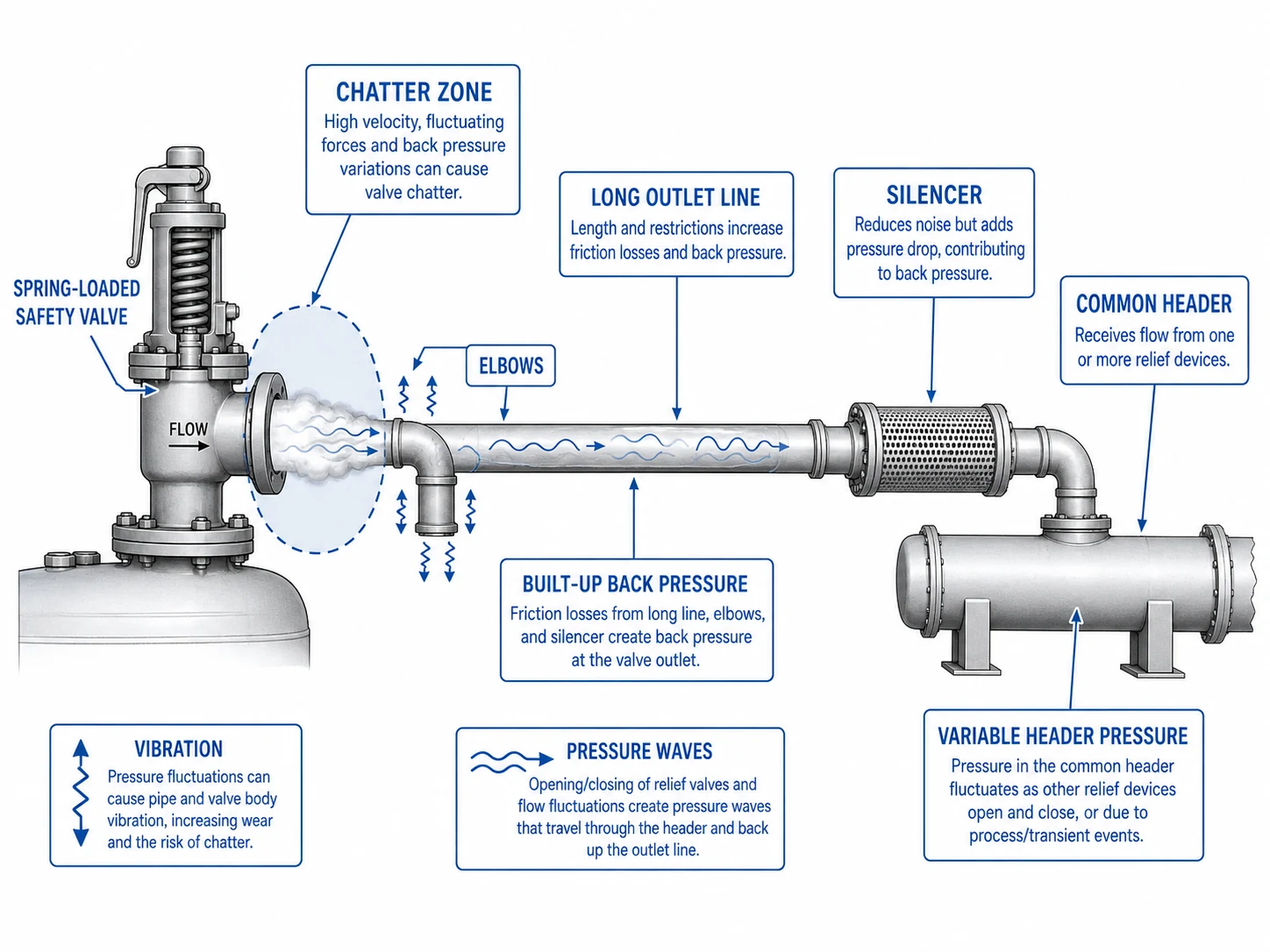
Chatter is rapid high-amplitude opening and closing in which the disc repeatedly contacts the seat. It can damage the nozzle, disc, guide, spindle, spring, bellows and connected piping, and it frequently produces post-lift leakage.
What Is Flutter?
Flutter is rapid oscillation of the moving parts without necessarily reaching full closure on every cycle. It can still reduce stable capacity, produce vibration and accelerate wear.
Back Pressure Is Usually One Part of the Causal Chain
Chatter and flutter are not proof of one isolated back-pressure problem. A complete diagnosis should also review:
- excessive inlet pressure loss after opening;
- an oversized orifice operating at low or unstable lift;
- process pressure pulsation or control instability;
- built-up or variable superimposed back pressure;
- unsuitable blowdown or internal adjustment;
- guide friction, deposits, corrosion or misalignment;
- two-phase, flashing or acoustically coupled flow;
- unsupported outlet piping, reaction load and body distortion;
- retained condensate or liquid hammer in the discharge line.
Where chatter has damaged the seat, set-pressure verification and a defined seat-tightness test may be required after repair. API 527 addresses seat-tightness methods for applicable metal- and soft-seated pressure relief valves, but it does not validate the outlet hydraulic system. See the API 527 Seat Tightness Test Guide.
Outlet Piping, Silencers, Common Headers and Flare Systems
Outlet Pipe Diameter, Length and Elevation
The outlet must carry the governing relief load without creating an unacceptable pressure condition. Small diameters, long runs, abrupt reducers, multiple elbows and high elevations increase resistance. Elevation and retained liquid can also add static head that is absent from a dry-gas calculation.
Silencers and Mufflers
Silencers reduce noise but add pressure loss and can accumulate condensate, scale or debris. Installing or replacing a silencer changes the original discharge-system basis and should trigger a new back-pressure, drainage and reaction-force review.
Common Discharge Headers
A common header can create variable superimposed pressure before one valve opens and additional built-up pressure during simultaneous relief. The analysis should identify credible combinations rather than assuming either that all devices open together or that every valve relieves alone.
Flare and Closed Vent Networks
A flare or closed vent must be evaluated as a network. Header pressure can depend on knockout equipment, flare-tip resistance, liquid accumulation, downstream restrictions, purge flow, compressor operation and the plant relief scenario. The pressure at an individual valve outlet may differ substantially from a single header design value.
Mechanical Loads, Drainage and Materials
Hydraulic acceptability does not prove mechanical acceptability. The outlet system should also be checked for reaction force, support, thermal expansion, nozzle loading, vibration, acoustic fatigue, low-point drainage and safe discharge. Pipe strain can distort the valve body and impair seat alignment.
| Outlet-System Condition | Potential Valve Effect | Required Review |
|---|---|---|
| Long or undersized tailpipe | High built-up pressure, reduced lift and vibration | Hydraulic pressure loss and mechanical support |
| Common flare header | Variable superimposed pressure and simultaneous-flow interaction | Credible network cases and dynamic conditions |
| Silencer or muffler | Added resistance, condensate retention and reaction load | Pressure drop, drainage and manufacturer limits |
| Blocked drain or liquid pocket | Hydrostatic back pressure, corrosion, water hammer and poor reseating | Low points, drain design, weather and process condensate |
| Corrosive or sour discharge | Bellows, nozzle, disc, guide, pilot and seal deterioration | Complete component material review; NACE MR0175 / ISO 15156 where specified |
| Unsupported outlet elbow | Body distortion, flange leakage and seat misalignment | Reaction, thermal movement and independent support |
使用 Safety Valve Installation Guide for inlet, outlet, support, drainage and commissioning checks. For flare and depressuring-system context, see the API 521 Pressure Relief Systems Guide.
Illustrative Engineering Example: A Header Modification Creates Chatter Risk
Initial Information
| Protected equipment | Gas separator |
|---|---|
| Valve set pressure | 10 barg |
| Required relieving capacity | 8,500 kg/h gas |
| Original outlet basis | Short atmospheric discharge line |
| Modified outlet | Extended line connected to a common recovery header |
| 叠加背压 | 0.7 barg for the reviewed operating case |
| Calculated built-up back pressure | 1.1 barg at the stated relieving flow |
Problem and Root Cause
The valve passed a workshop set-pressure test but chattered after the outlet modification. The bench test did not reproduce the new header pressure or discharge resistance. The combined illustrative outlet condition was 1.8 barg for that defined case, and the original valve selection had not been reviewed against it.
Corrective and Preventive Actions
- confirm the governing individual and simultaneous-relief cases;
- verify the required capacity and selected effective orifice;
- calculate inlet pressure loss and outlet pressure for the same scenario;
- compare the conventional valve with manufacturer-certified back-pressure data;
- review piping changes before changing valve type;
- evaluate balanced bellows or pilot-operated alternatives only after materials, vent, pilot and maintenance limits are defined;
- inspect the disc, nozzle, guide and spindle for chatter damage;
- update drawings, calculations, datasheets and management-of-change records.
Lesson: Set pressure can be correct while the installed relief system remains unstable or capacity-limited.
When Specialist Engineering or Manufacturer Review Is Required
Do not complete the back-pressure decision from one generic percentage or a web article alone when any of the following applies:
Variable Header Pressure
Downstream pressure changes materially with plant operation, purge flow, compressor status or relief combinations.
Two-Phase or Flashing Flow
The outlet contains liquid and vapor or the fluid changes phase through the valve and piping.
Multiple Simultaneous Devices
The common-header result depends on credible combinations of relief loads and timing.
Back Pressure Near the Performance Limit
The predicted condition approaches the manufacturer envelope or requires a capacity correction.
Dirty or Reactive Medium
Particles, polymer, wax, crystals, hydrates or corrosion can affect bellows, guides, pilots and outlet resistance.
Repeated Chatter or Mechanical Damage
The valve shows impact marks, guide wear, recurring leakage, vibration or unstable lift history.
Silencer or Major Outlet Modification
A new restriction, longer route, flare connection or recovery system changes the approved basis.
Toxic, Flammable or Sour Service
Bellows failure, bonnet vent release, pilot exhaust and leakage destination have additional consequences.
Eight-Step Back Pressure Review Process
- Define the protected equipment and governing relief scenario.
Confirm MAWP, set-pressure basis, fluid state, required capacity, relieving pressure and temperature. - Map the complete discharge path.
Include pipe sizes, lengths, elevations, fittings, branches, silencers, headers, scrubbers, knockout equipment and disposal destination. - Determine superimposed pressure cases.
Record minimum, normal, maximum, constant and variable downstream pressures before opening. - Calculate built-up back pressure.
Use the governing flow, fluid properties and credible simultaneous flows. Keep the pressure basis and scenario consistent. - Review the valve construction.
Compare conventional, balanced bellows and pilot-operated response using model-specific certified data. - Verify capacity and stability.
Confirm required versus certified capacity, effective orifice, inlet loss, outlet pressure, blowdown and chatter risk. - Check materials, mechanical loads and drainage.
Review reaction force, support, thermal expansion, nozzle load, condensate, bellows, pilot seals and corrosion. - Document and approve the final basis.
Update calculations, drawings, datasheets, manufacturer deviations, inspection requirements and management-of-change records.
Back Pressure Data to Include in an RFQ or Technical Review
| Required Information | Why It Matters |
|---|---|
| Protected equipment, MAWP and code basis | Defines the pressure boundary and applicable overpressure-protection route. |
| Governing relief scenario | Establishes the event that generates the required load. |
| Medium, composition, phase and relieving temperature | Controls sizing, hydraulics, materials and valve type. |
| Set pressure, relieving pressure and allowable accumulation basis | Connects valve operation to the equipment limit and capacity calculation. |
| Required relieving capacity | Defines the flow the valve and outlet system must handle. |
| Selected or required effective orifice | Prevents approval by connection size alone. |
| Minimum, normal and maximum superimposed pressure | Defines the outlet condition before opening and its variability. |
| Calculated built-up pressure | Shows pressure generated by the governing discharge flow. |
| Total back pressure for each applicable case | Supports comparison with the valve performance envelope. |
| Outlet piping isometric, size, length, elevation and fittings | Provides the hydraulic and mechanical calculation basis. |
| Header, flare, scrubber and simultaneous-relief information | Defines common-system pressure and flow interaction. |
| Silencer, muffler or downstream equipment data | Identifies pressure drop, drainage and reaction requirements. |
| Current valve model, nameplate and failure history | Supports replacement, root-cause and compatibility review. |
| Body, nozzle, disc, guide, spring, bellows, pilot and seal materials | Supports corrosion, temperature, sour-service and fouling review. |
| Inlet pressure loss and installation arrangement | Prevents treating outlet pressure as the only cause of instability. |
Documents to Request from the Supplier
- completed valve datasheet and general arrangement drawing;
- certified or project-accepted capacity for the stated fluid and pressure basis;
- allowable superimposed, built-up and total back-pressure information;
- capacity-correction or performance-envelope data where applicable;
- bellows material, design limits, bonnet vent and failure information;
- pilot type, sensing, dome and exhaust details where applicable;
- body, nozzle, disc, guide, spindle, spring, bellows, gasket and soft-part materials;
- installation, drainage, support and outlet-piping instructions;
- set-pressure, seat-tightness and pressure-test records as specified;
- inspection, maintenance, spare-parts and repair requirements;
- exact standard, edition, marking and certificate scope.
使用 Safety Valve Procurement Checklist for the broader bid review and supplier-document package.
Common Safety Valve Back Pressure Mistakes
Assuming Atmospheric Discharge
A flare, header, scrubber, silencer or recovery system has its own pressure behaviour and is not an open vent.
Using One Universal Percentage
Allowable back pressure depends on valve construction, fluid, relief case, certified data and manufacturer limits.
Mixing Different Relief Cases
A maximum header pressure from one case is combined with a built-up pressure from another without proving the combination is credible.
Adding a Silencer After Selection
A silencer changes resistance, reaction, acoustic response and drainage and requires renewed review.
Ignoring Simultaneous Relief
Individual valves may be acceptable alone while the common header is unacceptable under a credible combination.
Blocking a Bellows Bonnet Vent
This can defeat the balancing arrangement, hide bellows leakage and change the force balance.
Selecting a Pilot Only for High Back Pressure
Dirty medium, pilot exhaust, sensing loss, freezing and maintenance may make the design unreliable.
Ignoring Inlet Pressure Loss
Outlet pressure may be blamed for chatter while a restrictive inlet causes the nozzle pressure to collapse after opening.
Approving by Connection Size
Connection size does not prove effective orifice, certified capacity or back-pressure performance.
Repairing Chatter Damage Only
Seat repair will not prevent recurrence if the hydraulic or mechanical cause remains.
Standards and Authoritative Technical References
The required standard depends on the protected equipment, industry, jurisdiction, owner specification and valve construction. Use the official project-required edition; a web summary does not replace the copyrighted standard or responsible engineer’s approval.
| Reference | Role in This Topic | Official or Supporting Link |
|---|---|---|
| ASME BPVC Section XIII | Rules for overpressure protection of boilers, pressure vessels and piping systems within the ASME framework. | ASME official page |
| ASME BPVC Section I | Power-boiler construction context where boiler safety valves and discharge arrangements are involved. | ASME official page |
| ASME BPVC Section VIII, Division 1 | Pressure-vessel design, inspection, testing and certification context for the protected equipment. | ASME official page |
| API 520 Part I | Sizing and selection, including required capacity, valve configuration and the pressure basis used for capacity. | API official page · ZOBAI API 520 Guide |
| API 520 Part II | Installation and engineering analysis of pressure-relieving-device installations, including inlet and outlet conditions. | API official page |
| API 521 | Pressure-relieving and depressuring-system guidance for flare, vent and disposal networks. | API official page · ZOBAI API 521 Guide |
| API 527 | Seat-tightness testing after manufacture or repair; it does not validate outlet hydraulics or relieving capacity. | API official document · ZOBAI API 527 Guide |
| API RP 576 | Inspection practices for pressure-relieving devices, relevant after chatter, bellows damage, corrosion or recurring leakage. | Use the project-required official edition. |
| ISO 4126-1 | General product requirements for safety valves; it is a product standard and does not replace application analysis. | ISO official page |
| ISO 4126-4 | General product requirements for pilot-operated safety valves. | ISO official page |
| National Board VR / NBIC | Authorized pressure-relief-valve repair route where required by the owner or jurisdiction. | National Board VR official page |
FAQ About Safety Valve Back Pressure
安全阀中的背压是什么?
Back pressure is pressure acting at the valve outlet. It may exist before opening or develop after relieving flow passes through the outlet piping, silencer, header, flare, scrubber or recovery system.
What is the difference between superimposed and built-up back pressure?
Superimposed back pressure exists before the valve opens and may be constant or variable. Built-up back pressure is generated after opening by flow resistance in the discharge system.
什么是总背压?
Total back pressure is the outlet pressure acting during a defined relief event. It combines the applicable superimposed component with the built-up component for the same scenario, location and pressure basis.
How does back pressure affect a conventional spring-loaded safety valve?
Depending on valve geometry, outlet pressure can influence opening force balance, lift, effective capacity, blowdown and reseating. Excessive or variable pressure can contribute to flutter, chatter and seat damage.
Does a balanced bellows valve eliminate back pressure problems?
No. A bellows reduces the force effect of outlet pressure within its design envelope, but outlet hydraulics, certified capacity, bellows limits, material compatibility, bonnet venting and failure detection still require review.
Can a pilot-operated safety valve handle high back pressure?
Some configurations can handle selected high-back-pressure conditions, but suitability depends on the main valve, pilot type, dome, sensing path, exhaust arrangement, medium cleanliness and manufacturer performance data.
Can constant superimposed back pressure be corrected during calibration?
Some valve designs allow a manufacturer-approved cold differential test pressure or other correction for a defined constant superimposed pressure. This does not represent variable or built-up back pressure and does not validate the discharge system.
Does back pressure reduce safety valve capacity?
It can reduce or alter effective installed performance, depending on valve type and fluid. Capacity must be verified using the certified or manufacturer-approved basis for the actual downstream pressure condition.
Why does a safety valve chatter only after installation?
The installed system may add outlet resistance, variable header pressure, inlet pressure loss, vibration, liquid pockets or unstable flow that are absent from a workshop set-pressure test. Oversizing and process pulsation should also be checked.
Can a silencer be added to a safety valve outlet?
Only after its pressure drop, built-up back pressure, drainage, reaction forces, acoustic behaviour and manufacturer limits have been reviewed. A silencer changes the original discharge-system basis.
When should back pressure be recalculated?
Recalculate or revalidate it after changes to relief loads, outlet piping, silencers, headers, flare systems, downstream operating pressure, simultaneous-relief assumptions or process throughput.
Is there one allowable back pressure percentage for every safety valve?
No. The acceptable condition depends on valve construction, fluid, relief rate, pressure variability, certified data, applicable code and manufacturer limits.
Why is certified relieving capacity more important than connection size?
Connection size confirms the physical interface. Certified or project-accepted capacity establishes how much flow the selected valve and effective orifice can pass under defined pressure, fluid and configuration conditions.
What should be inspected after back-pressure-related chatter?
Inspect the nozzle, disc, seat, guide, spindle, spring, bellows, pilot components, piping supports and outlet system. After repair, perform the required calibration, seat-tightness test, documentation, locking and resealing under the approved quality route.
Need a Back Pressure or Chatter Review?
Send the protected equipment, current valve datasheet or nameplate, required relieving capacity, medium, set pressure, superimposed pressure range, built-up pressure calculation, outlet piping sketch, silencer data and common-header or flare information.
Send Outlet System Data 获取安全阀报价