هندسة صمام الأمان ذي المنفاخ المتوازن: فتحة تهوية الغطاء في صمام الأمان ذي المنفاخ المتوازن جزء من ترتيب مرجع الضغط حول المنفاخ وحجرة الزنبرك. سدّها، أو ترك غطاء النقل في مكانه، أو توجيهها إلى نظام يفرض ضغطًا غير مقصود يمكن أن يغيّر الحالة التي يفترضها تصميم الصمام. إذا …

هندسة صمام الأمان ذي المنفاخ المتوازن
فتحة تهوية الغطاء في صمام الأمان ذي المنفاخ المتوازن جزء من ترتيب مرجع الضغط حول المنفاخ وحجرة الزنبرك. سدّها، أو ترك غطاء النقل في مكانه، أو توجيهها إلى نظام يفرض ضغطًا غير مقصود يمكن أن يغيّر الحالة التي يفترضها تصميم الصمام. إذا ظهر سائل العملية لاحقًا عند فتحة التهوية، يصبح تسرب المنفاخ المحتمل مسار فحص مهمًا. يعتمد ترتيب التهوية الصحيح على التصميم الدقيق للصمام، والوسط والطور، وعواقب التسرب الخطير، ودرجة حرارة التصريف، والضغط الخلفي للمخرج، والضغط عند أي وجهة مقترحة للتهوية. قبل تغيير التهوية، تأكد من رسم الشركة المصنعة وظروف المشروع الفعلية بدلاً من معاملة الوصلة كمصرف بسيط أو ثقب غير مستخدم.
إجابة سريعة:
حافظ على فتحة تهوية الغطاء بالتهيئة المطلوبة لصمام المنفاخ المتوازن المختار. لا تسدّها لمجرد عدم خروج أي شيء عادة من الوصلة. إذا كانت الخدمة الخطرة تتطلب تهوية موجهة، فقيّم كلاً من الاحتواء الآمن والضغط الذي يمكن أن يفرضه التوجيه على الغطاء. تسرب العملية غير المتوقع من فتحة التهوية دليل يتطلب التحقيق، لكنه لا يثبت بحد ذاته فشلًا محددًا للمنفاخ، أو تغيرًا في ضغط الضبط، أو نتيجة سعة.
حافظ على فتحة تهوية الغطاء بالتهيئة المطلوبة لصمام المنفاخ المتوازن المختار. لا تسدّها لمجرد عدم خروج أي شيء عادة من الوصلة. إذا كانت الخدمة الخطرة تتطلب تهوية موجهة، فقيّم كلاً من الاحتواء الآمن والضغط الذي يمكن أن يفرضه التوجيه على الغطاء. تسرب العملية غير المتوقع من فتحة التهوية دليل يتطلب التحقيق، لكنه لا يثبت بحد ذاته فشلًا محددًا للمنفاخ، أو تغيرًا في ضغط الضبط، أو نتيجة سعة.
حدود الصفحة:
يركز هذا المقال تحديدًا على مرجع ضغط الغطاء، والسد، وتوجيه التهوية، ومؤشر فشل المنفاخ. للتأثير الأوسع لضغط المخرج على تهيئة الصمام، انظر
الضغط الخلفي والمنفاخ.
يركز هذا المقال تحديدًا على مرجع ضغط الغطاء، والسد، وتوجيه التهوية، ومؤشر فشل المنفاخ. للتأثير الأوسع لضغط المخرج على تهيئة الصمام، انظر
الضغط الخلفي والمنفاخ.
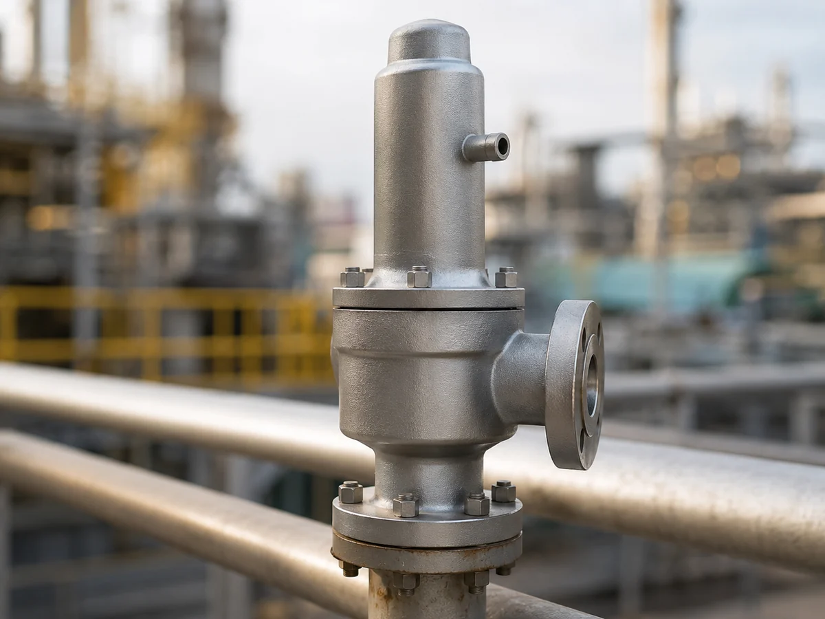
صورة WebP النهائية المرفوعة مقبولة في المرحلة 10C. مشهد صناعي توضيحي؛ ليس دليلاً على طراز ZOBAI محدد، أو شهادة، أو مشروع مركب.
ما الذي تفعله فتحة تهوية الغطاء فعليًا؟
يستخدم صمام الأمان ذو المنفاخ المتوازن ترتيب منفاخ لتقليل تأثير الضغط الخلفي للمخرج على القوى المتحكمة في فتح الصمام. المنفاخ مهم، لكن حالة الضغط في جانب الغطاء هي أيضًا جزء من التصميم.
من منظور حماية الضغط، السؤال المهم ليس ببساطة ما إذا كانت فتحة التهوية موجودة. السؤال هو ما الضغط الذي يُفترض أن تشير إليه حجرة الغطاء.
إذا كان التصميم يتوقع أن تبقى منطقة الغطاء (البنيه) قريبة من الضغط الجوي أو حالة مرجعية محددة أخرى، فإن فتحة تهوية مسدودة أو خط تهوية مضغوط خارجيًا يمكن أن يتعارض مع هذا الافتراض.
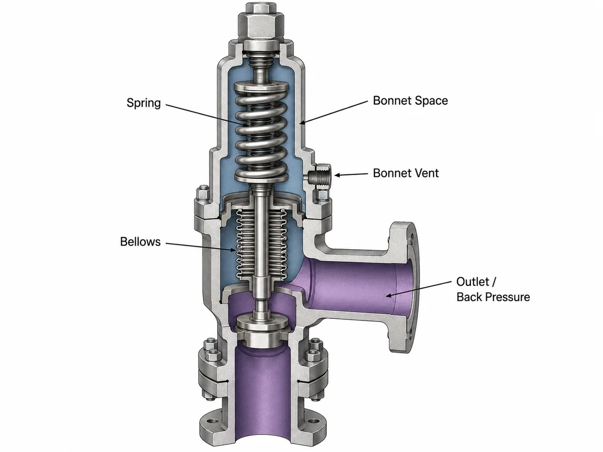
صورة WebP النهائية المرفوعة مقبولة في المرحلة 10C. رسم توضيحي هندسي مبسط؛ تختلف هندسة المنفاخ الدقيقة والمساحات الفعالة وترتيبات التهوية حسب تصميم الصمام.
لا تخلط بين ضغط الغطاء (البنيه) وضغط المخرج الراجع
| مصطلح الضغط | أين ينطبق ذلك | لماذا يهم هنا |
|---|---|---|
| ضغط التشغيل | حماية المعدات أثناء التشغيل العادي | يساعد في تحديد حالة التشغيل العادية ولكنه لا يحدد ضغط فتحة تهوية الغطاء. |
| ضغط الضبط | أساس الضغط لفتح الصمام وفقًا لتعريف الخدمة/الاختبار المطبق | يجب ألا يُستنتج من مظهر أو حالة فتحة تهوية الغطاء. |
| الضغط الخلفي المتراكب | ضغط المخرج الموجود قبل فتح الصمام | يعمل في نظام التفريغ ويجب تمييزه عن الضغط المفروض مباشرة على فتحة تهوية الغطاء. |
| الضغط الخلفي المتراكم | ضغط المخرج الناتج عن تدفق التفريغ بعد الفتح | يعتمد على مقاومة نظام التفريغ وليس هو نفسه ضغط فتحة تهوية الغطاء. |
| ضغط فتحة تهوية الغطاء | الضغط عند نقطة التوصيل المرجعية على جانب الغطاء | يمكن أن يؤثر على بيئة الضغط حول حجرة المنفاخ/الزنبرك إذا كان التصميم يتوقع حالة مرجعية أخرى. |
الحد الهندسي:
صمام المنفاخ المتوازن لا يلغي تلقائيًا كل قيود الضغط الراجع. إن الضغط الراجع المتراكب والمتراكم المقبول، وحدود الضغط/درجة الحرارة للمنفاخ، وضغط الغطاء المسموح به تخضع لتصميم الصمام الفعلي وبيانات الشركة المصنعة.
صمام المنفاخ المتوازن لا يلغي تلقائيًا كل قيود الضغط الراجع. إن الضغط الراجع المتراكب والمتراكم المقبول، وحدود الضغط/درجة الحرارة للمنفاخ، وضغط الغطاء المسموح به تخضع لتصميم الصمام الفعلي وبيانات الشركة المصنعة.
للعلاقة الهندسية الأوسع بين ضغط المخرج والتكوين المتوازن، راجع
صمامات أمان متوازنة بمنفاخ.
ماذا يحدث إذا كانت فتحة تهوية الغطاء مسدودة أو محجوبة؟
الانسداد المتعمد يشكل خطرًا واضحًا، ولكن فتحات التهوية في الغطاء العلوي (البونيه) قد تصبح أيضًا مقيدة بسبب الأوساخ أو الطلاء أو نواتج التآكل أو الحشرات أو العزل أو الجليد أو الحماية المؤقتة أثناء النقل التي لم تتم إزالتها أبدًا.
الانسداد المتعمد
قد تبدو الفتحة الملولبة غير مكتملة، لذلك قد يميل فريق الصيانة إلى تركيب سدادة عمياء أو غطاء. لا ينبغي القيام بذلك حتى يتم تحديد الفتحة بشكل قاطع والتحقق من متطلبات الشركة المصنعة للصمام.
الانسداد البيئي
قد تتطلب التركيبات الخارجية عناية خاصة فيما يتعلق بالتجمد والتلوث والحماية من الطقس. يجب ألا يؤدي ترتيب الحماية إلى تحويل فتحة تهوية وظيفية عن طريق الخطأ إلى غطاء علوي مغلق.
سلسلة الأعطال الهندسية
| الخطوة | الحالة المحتملة | العواقب الهندسية | ما يجب التحقق منه |
|---|---|---|---|
| 1 | تصبح فتحة التهوية مسدودة أو مقيدة | قد يُفقد الاتصال الحر بالمرجع المقصود للغطاء العلوي (البونيه). | حالة فتحة التنفيس الفعلية والترتيب المطلوب من الشركة المصنعة |
| 2 | قد ينحرف ضغط الغطاء عن الحالة المرجعية المقصودة | قد تختلف بيئة قوة الضغط حول المنفاخ والتجميع المتحرك عن افتراض التصميم. | ضغط الغطاء الفعلي، وتقييد فتحة التنفيس، وبنية الصمام |
| 3 | قد تتغير استجابة الصمام | قد يتأثر سلوك الفتح أو إعادة الإغلاق أو الاستقرار حسب التصميم. | بيانات الشركة المصنعة وتقييم هندسي مُتحكم فيه |
| 4 | يرى المشغل فقط وصلة مسدودة | لا يمكن للمظهر الخارجي تحديد تأثير الضغط. | لا تستنتج تغيرًا في ضغط الضبط أو تغيرًا في السعة دون دليل. |
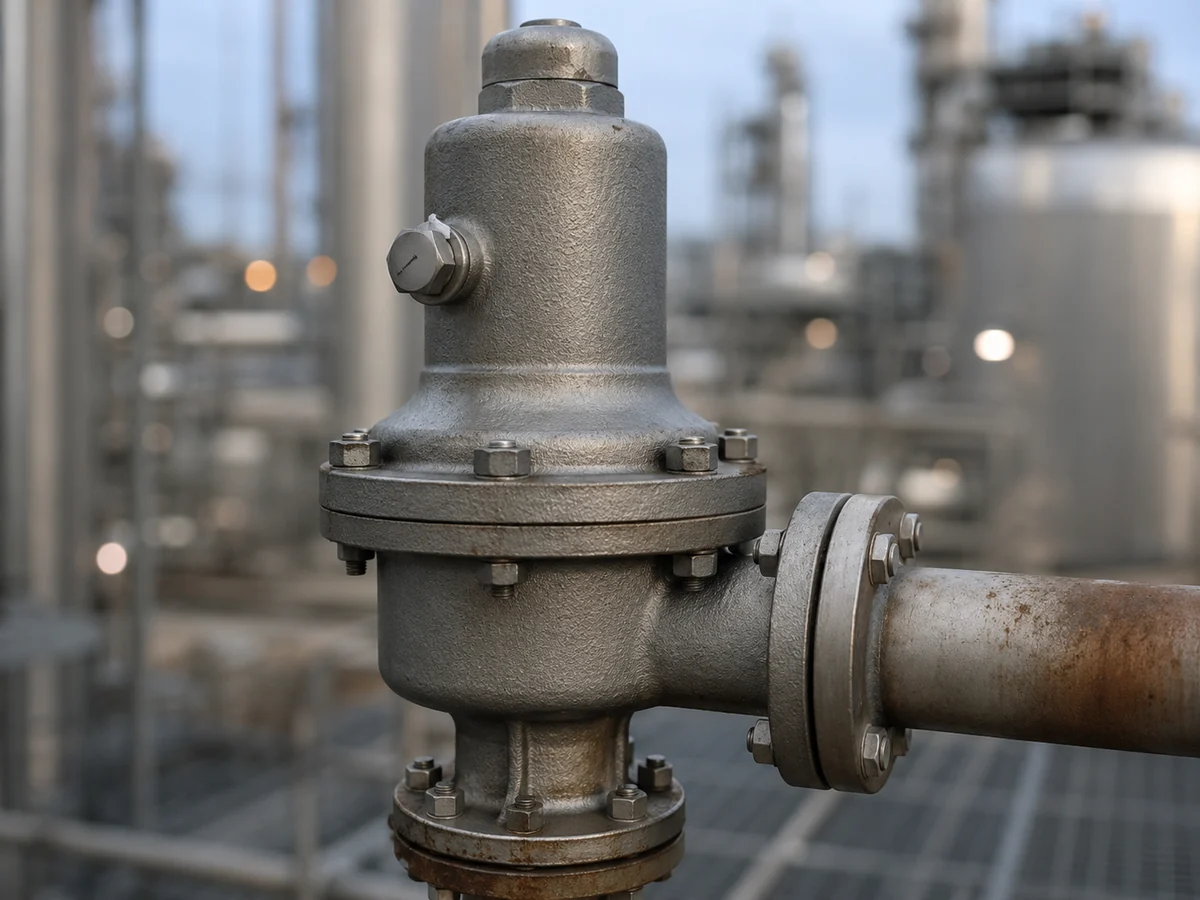
تم قبول صورة WebP النهائية المرفوعة في المرحلة 10C. رسم توضيحي واقعي فقط؛ يجب تأكيد مسار التنفيس الفعلي والقيود المقبولة لتصميم الصمام المحدد.
التنفيس إلى الجو أم التوجيه إلى موقع آمن؟
يجب التعامل مع التنفيس الجوي المباشر والتنفيس الموجه كترتيبات هندسية مختلفة بدلاً من قواعد عامة.
ترتيب التنفيس المباشر
قد يكون التنفيس المباشر مناسبًا عندما يتطلب تصميم الصمام المحدد هذا المرجع، ولا يسبب الوسط خطر إطلاق غير مقبول، ولا تسد البيئة الفتحة.
ترتيب التنفيس الموجه
قد تتطلب الخدمة السامة أو القابلة للاشتعال أو المسببة للتآكل أو الخطرة بأي شكل آخر توجيهًا محكمًا. يجب عندئذ مراجعة ضغط الوجهة والقيود والصرف وطول الخط والتعرض البيئي.
جدول قرار أولي لتوجيه التنفيس
| الترتيب المقترح | الفائدة المحتملة | المخاطر الهندسية الرئيسية | المراجعة المطلوبة |
|---|---|---|---|
| تنفيس مباشر إلى الغلاف الجوي المحلي المعتمد | مرجع ضغط بسيط مع أدنى مقاومة للمرور | تعرض الأفراد، الطقس، التلوث أو التجمد | خطر متوسط، متطلبات الشركة المصنعة وموقع التركيب |
| تنفيس موجه إلى موقع مفتوح آمن | ينقل أي تسرب محتمل من فشل المنفاخ بعيدًا عن الأفراد | القيود، تراكم السوائل، التجمد أو تأثيرات الخطوط الطويلة | توجيه الخط، التصريف، نقطة النهاية وإرشادات الشركة المصنعة |
| تنفيس متصل بنظام مغلق مشترك | احتمالية احتواء التسرب الخطير | قد يُفرض ضغط النظام المستقبِل على غطاء الصمام | نطاق ضغط الوجهة، فقد الضغط في الخط، تصميم الصمام والهندسة الهندسية للمشروع |
| تنفيس متصل بمشعب ضغط متغير | إدارة مركزية للتسرب | ضغط الغطاء المتغير يمكن أن يخلق حالة قوة متغيرة | الحد الأدنى/الأقصى لضغط المشعب وقبول الشركة المصنعة |
لا تنشئ مصدر ضغط جديد:
قد يؤدي التنفيس المتصل بوجهة مغلقة أو مضغوطة إلى تعريض مساحة الغطاء لضغط مختلف عن المرجع التصميمي. يجب مراجعة الاحتواء الآمن وسلوك ضغط الصمام الصحيح معًا.
قد يؤدي التنفيس المتصل بوجهة مغلقة أو مضغوطة إلى تعريض مساحة الغطاء لضغط مختلف عن المرجع التصميمي. يجب مراجعة الاحتواء الآمن وسلوك ضغط الصمام الصحيح معًا.
تغطي الاعتبارات العامة للتفريغ والدعم وخطوط الأنابيب في
دليل تركيب صمامات الأمان.
لمزيد من السياق حول التنفيس ونظام التصريف، راجع
أنظمة تنفيس الضغط API 521.
ماذا يمكن أن يخبرك التسرب من فتحة التهوية في الغطاء عن حالة المنفاخ؟
ظهور غاز أو بخار أو سائل عملية غير متوقع عند فتحة تهوية الغطاء قد يشير إلى فقدان الحد الفاصل للضغط الذي يفصل عادةً منطقة الغطاء عن جانب العملية أو مخرج الصمام.
لذلك، يعد تسرب المنفاخ مسارًا مهمًا للتحقيق، ولكن يجب التعامل مع تسرب فتحة التهوية كعرض وليس كتشخيص كامل.
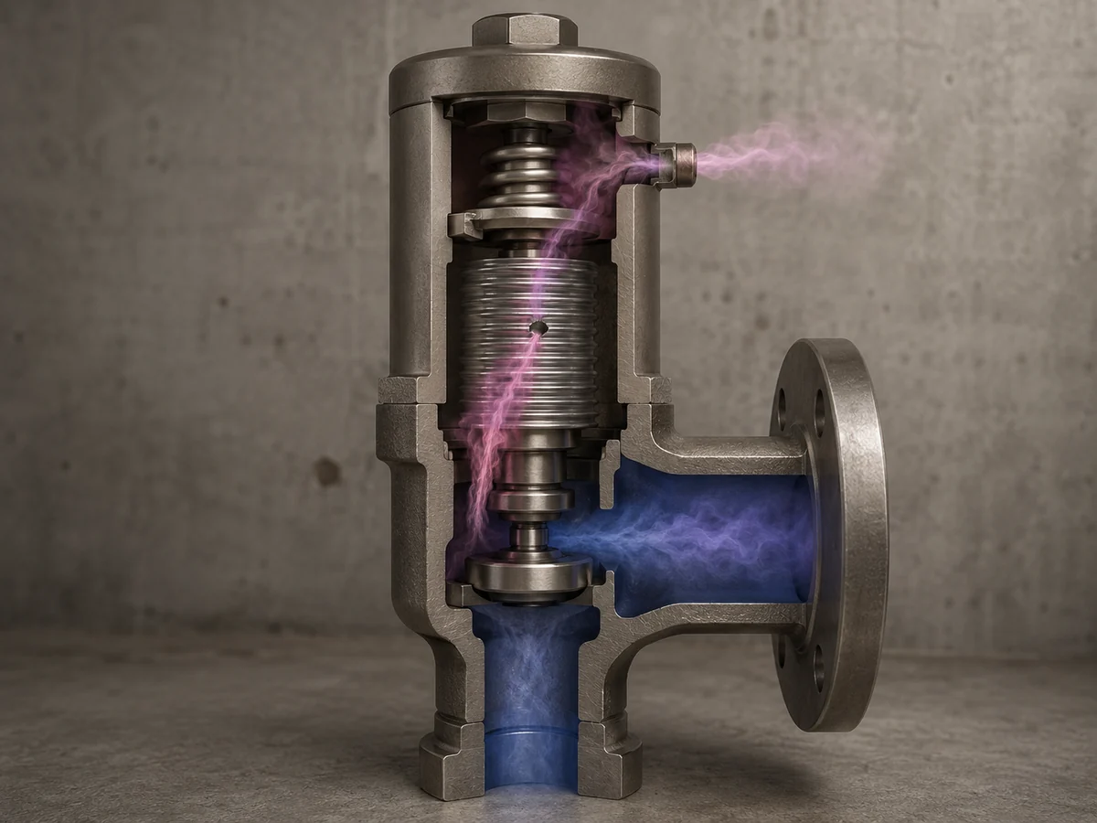
تم قبول صورة WebP المرفوعة النهائية في المرحلة 10C. توضيح مفاهيمي فقط؛ تسرب فتحة التهوية هو عرض تشخيصي، وليس دليلاً على عيب محدد أو تغيير في ضغط الضبط أو نتيجة سعة.
مصفوفة استكشاف أخطاء تسرب فتحة تهوية الغطاء وإصلاحها
| الملاحظة | القلق المحتمل | تحقق بعد ذلك | لا تستنتج بعد |
|---|---|---|---|
| يظهر بخار العملية عند فتحة التهوية للغطاء | احتمال وجود تسرب في المنفاخ أو مسار ضغط داخلي آخر | بنية الصمام، حالة المنفاخ، ضغط التشغيل وسجل الصيانة | أن العيب الدقيق في المنفاخ معروف |
| تقطر سائل من فتحة التهوية الموصولة | احتمال تسرب من العملية أو تكاثف أو دخول مياه خارجية | هوية السائل، التصريف، التوصيلات وسلامة المنفاخ | أن كل السائل نشأ من خلال منفاخ ممزق |
| تبقى فتحة التهوية جافة | لا يوجد تسرب خارجي واضح | الفحص/التوثيق العادي حسب المتطلبات | أن المنفاخ مثبت أنه سليم |
| يبدأ التسرب بعد الصيانة | احتمال وجود مشكلة في التجميع أو المنفاخ أو الإغلاق الداخلي | سجلات الإصلاح، هوية الأجزاء، التجميع والاختبارات المطلوبة بعد الإصلاح | أن فتحة التهوية للغطاء نفسها تسببت في العيب |
لا تقم بسد تسرب غير مفسر:
قد يؤدي إغلاق فتحة التهوية إلى إخفاء الأعراض مع تغيير حالة الضغط في الغطاء. يجب مراجعة حالة الصمام الأساسية وترتيب الحماية من الضغط المطلوب.
قد يؤدي إغلاق فتحة التهوية إلى إخفاء الأعراض مع تغيير حالة الضغط في الغطاء. يجب مراجعة حالة الصمام الأساسية وترتيب الحماية من الضغط المطلوب.
هل يؤدي فشل المنفاخ دائمًا إلى سلوك موحد للصمام؟
لا. يعتمد استجابة فشل المنفاخ على بنية الصمام.
تعتمد بعض ترتيبات الخراطيم المتوازنة بشكل أساسي على الخرطوم لعزل الضغط. وقد تتضمن التصميمات الأخرى ميزات موازنة مساعدة تهدف إلى التأثير على سلوك الصمام بعد حدوث عيب في الخرطوم.
| سؤال التصميم | لماذا هو مهم | الأدلة المطلوبة |
|---|---|---|
| هل يتم توفير الموازنة بواسطة الخرطوم فقط؟ | قد يؤدي فقدان سلامة الخرطوم إلى تغيير العلاقة المقصودة بين الضغط والقوة. | الرسم المقطعي من الشركة المصنعة وبيانات النموذج |
| هل توجد ميزة موازنة مساعدة؟ | قد يكون للصمام فلسفة مختلفة للاستجابة للأعطال. | وثائق تصميم مؤكدة خاصة بالنموذج |
| هل يمكن لفتحة التهوية في الغطاء تفريغ تسرب الخرطوم بأمان؟ | تؤثر إدارة الأعطال على تعرض الأفراد ومتطلبات التوجيه. | الوسط، الضغط، درجة الحرارة، ترتيب التهوية ومتطلبات الموقع |
| هل التشغيل المستمر مقبول بعد الاشتباه في فشل الخرطوم؟ | هذا قرار يتعلق بحماية الضغط والتشغيل، وليس استنتاجًا يعتمد على الفحص البصري. | إرشادات الشركة المصنعة، إجراءات المصنع، ومراجعة هندسية مسؤولة |
لذلك يجب أن يظل سؤالان منفصلين:
- هل الخرطوم لا يزال سليمًا؟
- كيف تم تصميم هذا الصمام بالضبط للتصرف إذا فقدت سلامة الخرطوم؟
لا يمكن استنتاج أي من الإجابتين بشكل موثوق من الوصف العام “صمام أمان متوازن الخرطوم”.”
أخطاء شائعة في تركيب فتحة تهوية الغطاء
| قرار التركيب | المخاطر الرئيسية | ما يجب تأكيده |
|---|---|---|
| تركيب سدادة أو غطاء أعمى | فقدان مرجع ضغط غطاء المحرك المقصود | رسم الشركة المصنعة ومتطلبات التشغيل |
| ترك حماية الشحن في مكانها | انسداد غير مقصود | تعليمات التركيب والفحص النهائي |
| التوصيل بخط ضغط مشترك | ضغط خارجي مفروض على غطاء المحرك | ضغط الوجهة وحد تصميم الصمام |
| استخدام أنابيب شديدة التقييد | مسار تفريغ ضغط مقيد أو فشل المنفاخ | الشركة المصنعة وهندسة المشروع |
| إنشاء جيوب سائلة | مشاكل تصريف أو تقييد أو تجمد | التوجيه والانحدار والنقاط المنخفضة والبيئة |
| تغطية فتحة التهوية بالعزل أو الطلاء | مسار تهوية مخفي أو مسدود | تفاصيل العزل ووصول الصيانة |
| دعم أنابيب التهوية من الصمام بطريقة تضيف حملاً | إجهاد ميكانيكي على وصلة صغيرة أو غطاء | دعم مستقل ومرونة الأنابيب |
| تغيير التوجيه دون إدارة التغيير أو تحديث المستند | قد يعتمد الفحص المستقبلي على أساس تصميم قديم | رسم معتمد وسجل تعديل ووثائق تشغيل |
كما أن أعمال تهوية الغطاء لا تصحح فقدان ضغط المدخل غير المرتبط أو سعة التصريف غير الكافية أو مقاومة نظام المخرج الزائدة. تتطلب هذه الحالات مراجعة هندسية خاصة بها.
قائمة فحص تهوية الغطاء
فحص بصري
- تحديد فتحة تهوية الغطاء بشكل مؤكد.
- التحقق من عدم وجود سدادات أو أغطية غير مصرح بها.
- تأكيد إزالة الحماية المؤقتة حيثما يلزم.
- تحقق من وجود أوساخ أو طلاء أو تآكل أو انسداد بسبب العزل أو الجليد.
- افحص الأنابيب الممددة والدعامات الميكانيكية.
- حدد نقطة النهاية.
- ابحث عن أي تسرب غير متوقع للعملية.
- تحقق من وجود مصائد سوائل واضحة أو مشاكل تصريف.
فحص المستندات
- الشركة المصنعة والطراز بالضبط
- رسم مقطعي
- تكوين المنفاخ
- خاصية الموازنة المساعدة، إن وجدت
- ترتيب فتحة تهوية الغطاء المقصود
- الوسط والطور
- درجات حرارة التشغيل والتنفيس
- ضغوط التشغيل والضبط
- ظروف الضغط الخلفي
- سجل الصيانة وفحص المنفاخ
نقاط توقف الفحص
- لا تغير وصلة التهوية حتى يتم التأكد من أن الفتحة هي فتحة تهوية الغطاء وفهم مرجع الضغط المطلوب.
- لا تعتبر فتحة التهوية الواضحة دليلاً على سلامة المنفاخ.
- لا تغلق التسرب الملحوظ في العملية كحل صيانة مؤقت.
- لا تقم بإدخال مجمع تهوية جديد دون التأكد من نطاق الضغط عند نقطة النهاية.
- لا تحدد فترة فحص عامة من هذه المقالة؛ يعتمد تكرار الفحص على شدة الخدمة وإرشادات الشركة المصنعة وإجراءات المصنع والمتطلبات المطبقة.

الصورة النهائية المرفوعة بصيغة WebP مقبولة في المرحلة 10C. مشهد توضيحي للتفتيش؛ وليس دليلاً على مشروع أو شهادة أو نتيجة اختبار محددة لشركة ZOBAI.
مصفوفة قرار تنفيس الغطاء حسب ظروف التشغيل
| حالة الخدمة | الاهتمام الرئيسي بالتنفيس | ما يجب تأكيده | التوجيه الهندسي |
|---|---|---|---|
| غاز أو بخار نظيف غير خطير | الحفاظ على مرجع الضغط المقصود | متطلب الشركة المصنعة للتنفيس والبيئة | قد يكون الترتيب المباشر ممكنًا إذا تمت الموافقة عليه |
| بخار سام أو قابل للاشتعال | إطلاق بعد تسرب محتمل للمنفاخ | تصنيف المخاطر والإنهاء | مراجعة توجيه التنفيس الآمن المناسب |
| وسط أكّال | إطلاق مادة أكالة بعد تلف المنفاخ | توافق المنفاخ والأنابيب والمواد المكشوفة | مراجعة المواد والتوجيه |
| بيئة خارجية متجمدة | انسداد بالجليد | حماية من الرطوبة ودرجة الحرارة والطقس | منع الانسداد دون إغلاق التنفيس |
| بيئة متسخة أو مغبرة | تقييد المواد الغريبة | طريقة الحماية وإمكانية الوصول للفحص | الحفاظ على اتصال ضغط حر |
| التنفيس متصل بنظام آخر | ضغط غير مقصود في الغطاء | ضغط الوجهة والتقييد والصرف | مراجعة الشركة المصنعة وهندسة النظام |
| تسرب عملية غير متوقع | احتمال فقدان سلامة المنفاخ | بنية الصمام ومصدر التسرب الفعلي | الترقية إلى فحص خاضع للرقابة |
هذه المصفوفة أداة فرز أولية. لا تغني عن حدود ضغط التنفيس الخاصة بالشركة المصنعة، أو حدود المنفاخ، أو الهندسة الهندسية للمشروع.
ما لا يثبته تنفيس غطاء الصمام
| الملاحظة | ما قد يخبرك به | ما لا يثبته |
|---|---|---|
| يظهر التنفيس مفتوحًا وواضحًا | لا يوجد انسداد مرئي | سلامة المنفاخ |
| التنفيس مسدود | قد يكون مرجع الضغط معرضًا للخطر | التأثير الدقيق على سلوك الفتح |
| ظهور سائل العملية عند التنفيس | احتمال فشل حد الضغط الداخلي | الموقع الدقيق لفشل المنفاخ |
| لا يوجد تسرب مرئي | لا يوجد تسرب خارجي واضح | ضغط الضبط، أو إحكام المقعد، أو السعة المطلوبة |
| يصل التنفيس إلى موقع آمن مخصص | نهاية الأنبوب محددة | أن ضغط التنفيس، أو القيد، أو توافق المواد مقبول |
حد السعة:
لا تثبت حالة تنفيس غطاء الصمام السعة التصريفية المطلوبة أو الموثقة/المعتمدة من الشركة المصنعة. ضغط الضبط ليس سعة، وحجم وصلة المدخل/المخرج لا يثبت اختيار الفوهة أو سعة الحماية.
للعلاقة المنفصلة بين حمل التخفيف المطلوب، والفوهة المختارة، والسعة الموثقة، راجع
حساب مقاسات صمامات الأمان وسعة التنفيس المعتمدة
دليلنا.
لا تثبت حالة تنفيس غطاء الصمام السعة التصريفية المطلوبة أو الموثقة/المعتمدة من الشركة المصنعة. ضغط الضبط ليس سعة، وحجم وصلة المدخل/المخرج لا يثبت اختيار الفوهة أو سعة الحماية.
للعلاقة المنفصلة بين حمل التخفيف المطلوب، والفوهة المختارة، والسعة الموثقة، راجع
حساب مقاسات صمامات الأمان وسعة التنفيس المعتمدة
دليلنا.
أي اختبار أو مستند يجيب عن أي سؤال؟
فحص تنفيس الغطاء هو جزء واحد فقط من التحقق من حالة الصمام. الاختبارات والسجلات المختلفة تجيب عن أسئلة هندسية مختلفة ولا ينبغي التعامل معها على أنها قابلة للتبادل.
| دليل | السؤال الرئيسي الذي تتم الإجابة عنه | ما لا يحل محله |
|---|---|---|
| الفحص البصري لتنفيس الغطاء | هل التنفيس مفتوح بشكل مرئي، وموجه بشكل صحيح، وخالٍ من التلف أو التسرب الواضح؟ | اختبار سلامة المنفاخ، أو التحقق من ضبط الضغط، أو مراجعة السعة |
| الرسم المقطعي / ورقة البيانات من الشركة المصنعة | ما هو البناء المقصود للصمام وترتيب تنفيس الغطاء؟ | فحص الحالة الفعلية للصمام المثبت |
| التحقق من ضغط الضبط | هل يفتح الصمام عند ضغط الاختبار المطلوب وفقًا للإجراء المعمول به؟ | تحديد السعة المطلوبة/المعتمدة أو تأكيد حالة المنفاخ |
| اختبار إحكام المقعد | هل يتوافق تسرب المقعد مع أساس القبول المعمول به؟ | تشخيص تسرب المنفاخ أو التحقق من السعة |
| فحص المنفاخ / التحقق من السلامة المعتمد | ما هي حالة المنفاخ وفقًا لإجراء الصيانة المعمول به؟ | حساب حمولة التنفيس أو مراجعة الضغط الخلفي للنظام |
| وثائق السعة | ما هو أداء التنفيس الموثق/المعتمد الذي ينطبق في ظل الظروف المحددة؟ | تأكيد أن سيناريو التنفيس المركب وخطوط الأنابيب صحيحة |
| سجل الصيانة / الإصلاح | ما الأعمال والأجزاء والفحوصات بعد الإصلاح التي تم تنفيذها؟ | الفحص الميداني الحالي عندما تتغير الحالة |
يجب تأكيد الوثائق المطلوبة ونطاق الاختبار مقابل الصمام المحدد، وتعليمات الشركة المصنعة، والكود المعمول به، ومسار الإصلاح، ومواصفات المشروع.
فحوصات المواد والوسائط لتوجيه تنفيس غطاء الصمام
توجيه التنفيس ليس مجرد مسألة ضغط. إذا فقد المنفاخ سلامته، فقد تتعرض أجزاء من مسار تنفيس غطاء الصمام التي تكون جافة عادةً لسائل العملية. لذلك يجب أن يأخذ مراجعة المواد في الاعتبار حالة الفشل المحتملة بالإضافة إلى التشغيل العادي.
| عامل الخدمة | المكونات التي يجب مراجعتها | الاهتمام الرئيسي |
|---|---|---|
| سائل عملية مسبب للتآكل | المنفاخ، الأجزاء المكشوفة من جانب غطاء الصمام، أنابيب التنفيس، التركيبات ومواد النهاية | يمكن أن يؤدي فشل المنفاخ إلى تعريض المكونات المعزولة عادةً لسائل مسبب للتآكل. |
| درجة حرارة تخفيف عالية | المنفاخ، بيئة الزنبرك، غطاء الصمام، أنابيب التنفيس، الأختام/الحشيات حيثما ينطبق ذلك | يجب أن تغطي القدرة الحرارية حالة الفشل والتوجيه ذات الصلة. |
| بخار متكثف | خط التنفيس، النقاط المنخفضة، ترتيب التصريف والنهاية | يمكن أن يتسبب المكثف في تقييد أو تآكل أو خطر تجمد. |
| وسط سام أو قابل للاشتعال | أنابيب التنفيس، الوصلات، الوجهة وترتيب المراقبة حيثما ينطبق ذلك | يجب مراعاة إدارة التحرير دون فرض ضغط غطاء غير مقبول. |
| خدمة ملوثة أو خدمة تتسبب في بلمرة. | منطقة المنفاخ، فتحة التنفيس وأي توجيه للأنابيب صغيرة القطر | يمكن أن تقيد الرواسب الحركة أو نقل الضغط. |
| بيئة خارجية بدرجة حرارة منخفضة | مخرج التنفيس، النقاط المنخفضة والحماية من الطقس | يمكن أن تتجمد الرطوبة أو المكثفات وتسد المسار. |
حدود المواد:
تسمية مادة الجسم وحدها لا تثبت ملاءمة تنفيس الغطاء أو المنفاخ. قم بتأكيد المنفاخ، والمكونات المتأثرة، وبيئة الزنبرك، والحشيات/الأختام وأي أنابيب تنفيس مقابل الوسط الفعلي ودرجات الحرارة.
تسمية مادة الجسم وحدها لا تثبت ملاءمة تنفيس الغطاء أو المنفاخ. قم بتأكيد المنفاخ، والمكونات المتأثرة، وبيئة الزنبرك، والحشيات/الأختام وأي أنابيب تنفيس مقابل الوسط الفعلي ودرجات الحرارة.
ما يجب تأكيده قبل تغيير ترتيب تنفيس الغطاء
لا تقم بتعديل التنفيس بناءً على خيط التوصيل أو الأنابيب المجاورة فقط. يجب ربط قرار التنفيس بالمعدات المحمية وأساس نظام التحرير الفعلي.
المعدات المحمية وأساس التحرير
- المعدات المحمية
- سيناريو التنفيس الحاكم
- ضغط التشغيل
- أقصى ضغط تشغيل آمن (MAWP) أو ضغط التصميم
- ضغط الضبط
- السعة المطلوبة للتنفيس وأساس السعة
- درجة حرارة التنفيس
الخدمة والضغط الخلفي
- الوسط والطور
- الخصائص السامة أو القابلة للاشتعال أو المسببة للتآكل
- الضغط الخلفي المتراكب
- الضغط الخلفي المتراكم
- ضغط ثابت أو متغير
- ترتيب مشعب التفريغ
تركيب الصمام
- الشركة المصنعة
- الطراز/النوع الدقيق
- تصميم وخامة المنفاخ (Bellows)
- بيئة عمل الزنبرك
- تصميم المقعد/المانع للتسرب حيثما ينطبق
- خاصية الموازنة المساعدة، إذا كانت مثبتة
- وصلة تنفيس غطاء الصمام (Bonnet)
- مرجع غطاء الصمام المعتمد من الشركة المصنعة
مسار التنفيس المقترح
- ترتيب مباشر أو عبر أنابيب
- حجم الخط وطوله
- الوصلات والقيود
- نقاط التصريف والنقاط المنخفضة
- موقع الإنهاء
- الضغط الأدنى والأقصى لنظام الاستقبال
- التعرض البيئي
- مواد خط التنفيس
المعلومات المطلوبة للمراجعة الهندسية أو طلب عرض السعر
- لوحة بيانات الصمام الحالية وصور فوتوغرافية واضحة
- ورقة البيانات الحالية والرسم المقطعي/التجميعي إن وجد
- المعدات المحمية وسيناريو التنفيس الحاكم
- الوسط والطور والخواص الخطرة
- ضغط التشغيل، أقصى ضغط تشغيل آمن/ضغط التصميم، وضغط الضبط
- سعة التصريف المطلوبة وأساس الحساب، إن وجدت
- درجة حرارة التنفيس
- الضغط الخلفي المتراكب والمتزايد
- ترتيب أنابيب الدخول والخروج
- وصلة تنفيس الغطاء الحالية ونقطة الإنهاء
- مسار التنفيس الجديد المقترح ونطاق ضغط الاستقبال
- مواد المنفاخ والتقليم وخط التنفيس إن كانت معروفة
- الكود المعمول به والنسخة المعتمدة ومواصفات المشروع والمستندات المطلوبة
إذا أدى الفحص إلى استبدال أوسع للصمام أو مراجعة التكوين، استخدم
دليل اختيار صمامات الأمان
كخطوة تالية بدلاً من استبدال الصمام بناءً على المظهر أو حجم الوصلة فقط.
سيناريوهات هندسية مركبة
السيناريو 1 — انسداد فتحة التنفيس الخارجية بالجليد
الملاحظة: صمام أمان بمنفاخ متوازن مركب في الهواء الطلق وتتجمد الرطوبة حول فتحة تنفيس الغطاء.
اعتبار هندسي: قد لا يحافظ الغطاء بعد الآن على مرجع الضغط المقصود في تصميم الصمام.
الاتجاه التصحيحي: تأكيد ترتيب التنفيس المعتمد، واستعادة مسار تنفيس حر وفقًا لإجراءات المصنع المعمول بها، والتحقيق في مصدر الرطوبة أو المتكثفات.
الوقاية: استخدم ترتيبًا جويًا معتمدًا من الشركة المصنعة/المشروع يمنع الانسداد البيئي دون إغلاق أو ضغط غير مقصود على فتحة التنفيس.
السيناريو 2 — الأبخرة الخطرة تتطلب تنفيسًا موجهًا
الملاحظة: تحتوي المعدات المحمية على بخار خطير، والإطلاق المباشر الموضعي بعد تسرب محتمل في المنفاخ غير مقبول وفقًا لفلسفة السلامة في الموقع.
اعتبار هندسي: يمكن أن يؤدي توجيه التنفيس إلى تحسين إدارة الإطلاق، ولكن الوجهة المغلقة أو المتغيرة الضغط قد تفرض ضغطًا على الغطاء.
الاتجاه التصحيحي: راجع ضغط الوجهة، وتقييد الخط، والتصريف، وتوافق المواد، والإنهاء جنبًا إلى جنب مع متطلبات الشركة المصنعة للصمام.
الوقاية: أدرج ترتيب تنفيس الغطاء ونطاق ضغط الوجهة في ورقة بيانات المشروع ومراجعة خطوط الأنابيب بدلاً من معالجة التنفيس كتفصيل للتركيب الميداني.
السيناريو 3 — ظهور سائل العملية عند تنفيس الغطاء
الملاحظة: يتم اكتشاف بخار العملية عند تنفيس الغطاء الذي لم يُظهر أي إطلاق سابقًا.
اعتبار هندسي: يصبح فقدان سلامة المنفاخ أو مسار ضغط داخلي آخر آلية فشل محتملة.
الاتجاه التصحيحي: اتبع عملية القرار المعتمدة في الموقع للحفاظ على الحماية من الضغط الزائد أثناء مراجعة بناء الصمام، وحالة المنفاخ، وسجل الصيانة، والاختبارات المطلوبة.
الوقاية: احتفظ بسجلات الإصلاح، وتحقق من قطع الغيار وفحوصات ما بعد الصيانة، ولا تستخدم سد فتحة التنفيس كبديل عن التشخيص.
هذه سيناريوهات هندسية مركبة للتدريب. وهي لا تمثل مشاريع العملاء، أو سجلات الاختبار الميداني لشركة ZOBAI، أو دليل أداء خاص بنموذج معين.
المراجع الفنية والحدود الهندسية
يجب مراجعة تنفيس الغطاء كجزء من تركيب جهاز تخفيف الضغط الكامل ونظام التخفيف/التخلص. المراجع أدناه تخدم أدوارًا مختلفة كأدلة؛ الأمثلة الخاصة بالشركة المصنعة لا تثبت بناء أو أداء كل صمام أمان متوازن المنفاخ.
-
Spirax Sarco — تركيب صمام الأمان
— إرشادات التركيب التي تغطي تنفيس غطاء الصمام المتوازن، والانسداد بالمواد الغريبة أو الجليد، واعتبارات الضغط. -
المركز الأوروبي لسلامة العمليات — ورقة تعلم صمام الأمان متوازن المنفاخ
— مادة تعليمية لسلامة العمليات تتناول سدادة الشحن المتروكة على تنفيس غطاء المنفاخ المتوازن واحتياطات التنفيس ذات الصلة. -
LESER — أساسيات التصميم
— مرجع هندسي من الشركة المصنعة يصف مناطق ضغط الغطاء وتكوينات المكبس المتوازن المساعدة. -
LESER — الدليل الهندسي
— إرشادات الشركة المصنعة ذات الصلة بتركيب أنابيب التنفيس الآمنة للوسائط القابلة للاشتعال أو السامة أو المسببة للتآكل. -
Emerson Crosby — كشف تسرب المنفاخ
— مثال خاص بطراز يوضح مراقبة تسرب المنفاخ، ومكبس احتياطي، والانبعاثات عبر تنفيس الغطاء؛ وهو ليس قاعدة عامة لتصميم الصمامات. -
معهد البترول الأمريكي — API 520 الجزء الثاني
— سياق أوسع لتركيب أجهزة تخفيف الضغط. -
معهد البترول الأمريكي — API المعيار 521
— سياق أوسع لأنظمة تخفيف الضغط وخفضه.
تحقق من إصدار المعيار المعتمد، ومتطلبات الشركة المصنعة، والسلطة المحلية للمشروع الفعلي. لا تثبت هذه المراجع صلاحية الشهادة أو السعة أو علامة الكود أو ملاءمة طراز معين لأي صمام ZOBAI.
أسئلة متكررة
لماذا يحتاج صمام الأمان ذو المنفاخ المتوازن إلى تنفيس الغطاء؟
فتحة التهوية في الغطاء تساعد في الحفاظ على مرجع الضغط المطلوب على جانب الغطاء في ترتيب المنفاخ المتوازن. يعتمد الضغط المطلوب بدقة وتكوين فتحة التهوية على تصميم الصمام وبيانات الشركة المصنعة.
هل يمكن سد فتحة التهوية في الغطاء العلوي لصمام الأمان ذي المنفاخ المتوازن؟
لا تقم بتوصيله ما لم تسمح الشركة المصنعة المختارة صراحةً بهذا الترتيب. يمكن أن يؤدي انسداد فتحة التهوية إلى تغيير حالة ضغط الغطاء التي يفترضها تصميم الصمام.
هل يمكنني توصيل فتحة التهوية العلوية بنظام أنابيب مغلق؟
فقط بعد المراجعة الهندسية. قد يكون النظام المغلق مناسبًا لإدارة التسرب في بعض الخدمات، ولكن يجب أن تظل ضغوطه الدنيا والقصوى، والقيود، والتصريف، والنهاية متوافقة مع مرجع ضغط الغطاء المطلوب للصمام.
ماذا يعني تسرب الهواء من فتحة غطاء المحرك؟
يمكن أن يشير تسرب سائل العملية غير المتوقع إلى فقدان سلامة المنفاخ أو مسار تسرب داخلي آخر، اعتمادًا على تصميم الصمام. يجب أن يؤدي ذلك إلى إجراء تحقيق بدلاً من سد فتحة التنفيس فورًا.
هل يعني تسرب فتحة غطاء المحرك دائمًا أن المنفاخ قد تمزق؟
لا، إنه عرض مهم، ولكن يجب التحقق من مسار التسرب الفعلي وحالة المنفاخ وبناء الصمام.
هل يجب توجيه فتحات الغطاء العلوي للخدمات السامة أو القابلة للاشتعال إلى مكان آمن؟
قد يكون التوجيه الآمن مطلوبًا عندما يشكل التسرب المحتمل خطرًا غير مقبول. يعتمد الوجهة الدقيقة وترتيب الأنابيب على الوسط، ومتطلبات الموقع، وتصميم الصمام، وضغط الوجهة، وتعليمات الشركة المصنعة.
ما هي المعلومات التي يجب التحقق منها قبل تعديل أنابيب تنفيس الغطاء؟
تأكد من طراز الصمام وبنية المنفاخ، والمعدات المحمية وسيناريو التنفيس، والوسط والطور، وضغط التشغيل، أو MAWP أو ضغط التصميم، وضبط الضغط، ودرجة حرارة التنفيس، والضغط الخلفي المتراكب والمتراكم، وضغط الوجهة المقترح، وقيود خط التنفيس والمواد، ومتطلبات الشركة المصنعة والمشروع المعمول بها.
هل تحتاج إلى مراجعة هندسية لترتيب تنفيس الغطاء؟
أرسل المعدات المحمية، وسيناريو التخفيف الحاكم، والوسط والطور، وضغط التشغيل، أو MAWP أو ضغط التصميم، وضبط الضغط، وسعة التخفيف المطلوبة والأساس إذا كان متاحًا، ودرجة حرارة التخفيف، والضغط الخلفي المتراكب والمتراكم، وطراز الشركة المصنعة/الصمام، ومعلومات المنفاخ والمواد، ووصلة تنفيس الغطاء، والتوجيه الحالي، ونطاق ضغط الإنهاء المقترح، والرسومات أو الصور المتاحة.