了解为什么3%入口损失准则并非通用的合格/不合格判定规则、哪些因素决定其适用性,以及如何审查超过该准则的安全阀安装。.

A 3% 入口压力损失 该准则在审查泄压阀安装时被广泛采用,但它并非适用于每台安全阀、每项标准或每种工况的通用合格/不合格判定规则。.
Under API 520 Part II, the familiar 3% value is an important screening criterion for nonrecoverable inlet pressure loss. API’s official standards information identifies Part II, 7th Edition as the published edition used for this article and notes that it introduced an 工程分析 用于评估泄压装置安装的路径。.
这一区分决定了该数值应如何使用。工程师不应从“压降是否低于3%?”开始,更合理的顺序是:先确定控制基准,确认所计算的是哪种损失,识别阀门与感压配置,然后再判断这一常见判据是否确实适用于筛选。.
低于3%的结果本身并不能保证阀门动作稳定;高于3%的结果本身也不能证明所有安装都必须否定。真正重要的是该数值背后的工程依据。.
3%入口压降判据的含义——以及它不能证明什么
根据 API 520 第 II 部分,常用判定准则涉及 被保护设备与泄压阀之间的总不可恢复压力损失,并以阀门整定压力为基准.
该词 不可恢复 很重要。入口压力损失并不只是被保护设备与安全阀之间可能存在的每一个压差。摩擦、湍流、管件、节流件及其他流动阻力都会在流体流向安全阀的过程中消耗压力。高程和可回收速度效应必须按适用的水力计算方法处理,而不能不加区分地归入“3%压降”。”
流量基准也必须说明。按API惯例,安全阀额定排量是常见的设计基准,但不能写成在每一种允许配置下的每一个入口损失计算都必须始终采用额定流量。某些阀门行为和工程分析路径可能会改变适用的基准。.
因此,像“入口损失 = 2.7%”这样孤立的表述是不完整的,除非已知计算基准。.
| 计算结果 | 其确立的内容 | 其未确立的内容 |
|---|---|---|
| 该安装满足适用的入口损失筛选准则 | 该特定水力筛选条件已满足 | 在所有泄放工况下均能保证稳定运行 |
| 该安装超出常见的筛选值 | 需要进一步技术审查 | 必然发生颤振、必然自动失效或普遍被规范否决 |
| 经许可的工程分析支持该安装方案 | 针对具体安装可能存在有记录的技术依据 | 可以忽略该排量、阀门特定限制或项目要求 |
这是对常见“3%规则”的首个重大修正: 该百分比是筛选判据,而非物理稳定性边界.
泄压阀具有系统动态特性,单一百分比无法完全描述。因此,满足该筛选条件不应被解读为“阀门不会颤振”,正如超出该条件也不应被解读为“阀门将会颤振”。”
什么决定 3% 判定准则是否适用?
在套用任何百分比准则之前,先确定实际管辖该装置的相关规范。.
API、ASME、ISO、国家法规、业主规范以及制造商说明都可能对项目产生影响,但它们的适用范围和效力并不相同。.
关于这些角色的整体说明,请参阅 ZOBAI 的 安全阀标准指南. 对于明确采用 API 方法的项目,请参阅单独的 API 520 安全阀工程指南 提供更全面的选型与安装依据。.
从适用依据入手,而非百分比
ASME 指明 BPVC Section VIII Division 1, 2025 为本评审所采用的现行版本。.
在 2025 BPVC Section VIII Division 1 结构中,与本主题相关的入口压力损失材料见 非强制性附录 M, ,位于安装与操作指导部分,并明确涵盖装置及可压缩流体工况范围。该状态应予保留,不应简化为“ASME 普遍要求 3%”。”
ISO 对同一问题提供了不同的说明。. ISO 4126-9 具体是 ISO 4126 系列中关于应用与安装的部分。其发布范围涵盖安全阀和先导式安全阀,并指出安装信息假定 单相流.
因此“项目遵循 ISO 4126”仍不足以说明问题。相关部分和适用工况范围至关重要。.
然后确定装置配置
接下来的问题是安装何种泄压装置。.
常规直接弹簧载荷式安全阀、平衡式结构和先导式安全阀不一定遵循相同的稳定性或感压逻辑。对于先导式装置,先导阀从何处感测被保护系统的压力可能尤为重要。.
这并不意味着“先导式 = 不受 3% 规则约束”。正确的区分更为具体: 特定的传感布置可能会改变入口压力损失对阀门控制的影响,而主阀入口水力特性仍可能影响可用的泄放压力和排量.
需要先了解工作原理区别的读者可使用单独的 先导式安全阀工作原理指南 而不是将本文扩展为完整的先导阀教程。.
确认使用工况与泄放工况
主导路径还可能取决于该装置所防护的对象。.
仅针对液体热膨胀这一明确工况,不应自动推广至工艺加热、汽化、火灾暴露、出口堵塞或其他可信的超压工况。同样,未经核对相应标准依据,不应假定单相安装基础可覆盖两相泄放工况。.
ISO 明确了这一范围边界:第 9 部分指出其安装信息以单相流为前提,而 ISO 4126-10:2024 分别针对气液两相流的安全阀和爆破片选型计算进行说明。.
实际流程为:
控制依据 → 装置与感压配置 → 使用工况与泄放工况 → 计算依据 → 适用的入口压损判据。.
百分比在这些问题之后确定。.
为什么入口压损会影响安全阀的稳定性
当阀门开始排放后,入口压损为何重要就更加清楚了。.
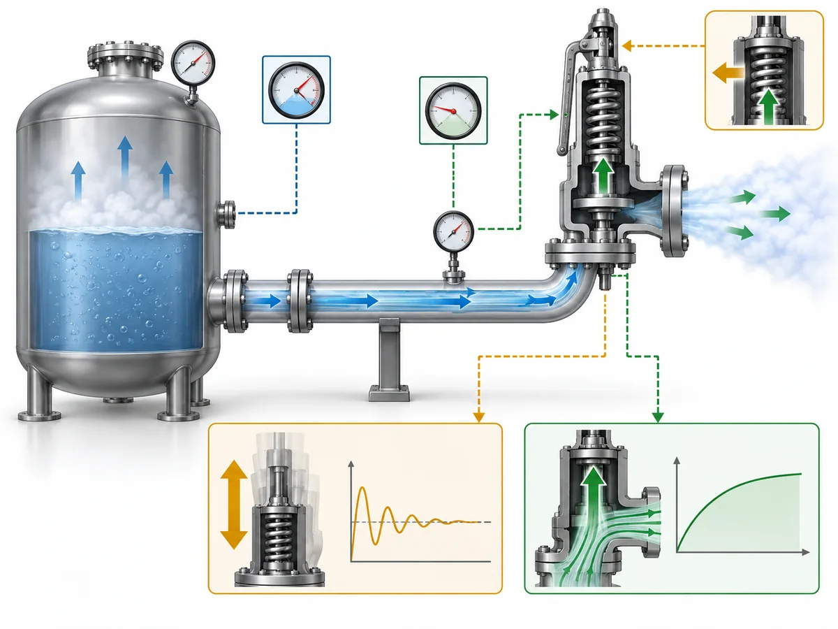
在泄放事件发生前,受保护系统与阀门入口处的压力可能较为接近,仅存在相关的静压效应差异。一旦形成较大的泄放流量,入口管路中的摩擦和湍流就会产生不可恢复的压力损失。.
此时阀门入口压力可能低于受保护设备的压力。.
对于直接作用弹簧式安全阀,这一变化会与控制开启、阀瓣升程和回座的力平衡相互作用。简化过程为:
受保护系统压力升高 → 阀门开启 → 泄放流量增大 → 入口压损增大 → 阀门入口压力变化 → 阀门响应变化 → 流量再次变化。.
在管路与阀门特性不利组合的情况下,这种反馈可能导致运行不稳定。.
但将这一机理简单归结为“超过3%时安全阀发生颤振”仍然是不正确的。入口压损只是系统的一部分。阀门特性、泄放需求、出口背压、选型计算以及动态或声学相互作用也会影响稳定性。.
出口背压与入口压力损失是相互独立的工程变量。研究下游侧问题的读者应使用专门的 弹簧式安全阀背压指南 而不是将两项计算合并处理。.
入口压力损失还会引发第二个问题,不应在颤振讨论中被忽略: 泄放能力.
不可恢复的压力损失会降低泄放阀入口在流动过程中可用的压力。当该影响较为显著时,必须单独校核其对泄放能力的影响。.
这给工程师提出了两个不同的问题:
阀门/系统是否预期能够稳定运行?
已安装的阀门在实际入口工况下是否仍能提供所需的泄放能力?
通过其中一项校核并不自动回答另一项。.
当熟悉的 3% 判据并非决策的全部依据时
“非通用”并不意味着“3% 可以被忽略”。它意味着公认的工程框架中包含与适用范围相关的工况,在这些工况下,仅凭与常见筛选值进行简单比较无法完成判定。.
具体安装可能需要有文件记录的工程分析
API 官方关于以下内容的资料 API 520 第II部分,第7版 确认该已发布版本引入了用于评估泄压装置安装的工程分析。.
在 API 520 第二部分中,该针对具体安装的路径可以超出单一摩擦损失百分比的范围,并在适用时考虑排量影响、阀门行为、力平衡、系统响应、运行历史或动态相互作用。.
这不应被表述为“允许工程师忽略 3% 的例外情况”。该分析的存在是为了确定是否 特定安装工况 具有可辩护的技术依据。.
已知的不稳定行为会改变该判断。在本文采用的 API 520 Part II 工程分析框架下,对于已有可信颤振证据的现有安装,不应仅因后续能够出具计算书就将其重新判定为可接受。.
狭窄的热膨胀工况需要作狭义解释
API 520 Part II 对仅由环境受热引起的液体水力膨胀这一边界狭窄的工况,也与一般入口损失筛查路径区别对待。.
该词 仅由 至关重要。.
同样的处理方式不得擅自扩展至每一条封闭液体管线、每一个热泄放阀、可能使液体汽化的工艺加热工况,或存在其他可信超压工况的系统。.
If the duty no longer fits that narrow basis, the ordinary inlet-loss assessment has to be revisited.
Remote sensing changes the question, not the laws of hydraulics
API 520 Part II gives specific treatment to a remotely sensed pilot-operated pressure relief valve. In that arrangement, the pilot can sense pressure at a location selected to represent protected-system pressure rather than relying only on the pressure at the main valve inlet.
That can alter the relationship between main-inlet pressure loss and pilot control.
It does 不 mean the pressure loss in the main inlet disappears. The main valve still has to pass the required relieving flow, so available inlet pressure and capacity remain relevant.
The sensing line itself also becomes part of the review. Its location, pressure losses, and compatibility with the chosen pilot design may require manufacturer-specific information.
Flow regime can change the standards basis
ISO 4126-9 states that its installation information assumes single-phase discharge, while ISO 4126-10:2024 deals with gas/liquid two-phase sizing.
That supports a scope boundary, not an invented second “two-phase 3% rule.”
If the relieving condition is two-phase, the correct action is to verify the applicable method—not to transfer a single-phase rule unchanged or invent an alternative percentage.
Across these examples, the engineering principle is consistent: do not search for an exception to 3%; identify the actual governing route for the device, duty, sensing arrangement, and installation.
How to Review an Installation Above the Familiar Criterion
An inlet-loss result above the familiar screening value is a reason to investigate. It is not enough information to approve or reject the installation.
1. Verify that the pressure-loss calculation is comparable with the criterion
Check the calculation boundary, inlet pipe geometry, fittings, reducers, restrictions, fluid properties, relief phase, and any upstream device that contributes hydraulic resistance.
A technically correct pressure-drop calculation can still be the wrong comparison if it uses a different pressure quantity or boundary from the governing criterion.
For broader installation geometry and piping considerations, see the 安全阀安装指南.
2. State the flow basis explicitly
Confirm whether the calculation uses rated capacity, required relieving flow, or another basis permitted for the actual device and assessment method.
Do not hide the assumption inside the hydraulic software or calculation sheet. It is one of the inputs that can materially change the reported loss.
3. Check relieving capacity separately
If inlet loss is significant, determine whether the installed inlet pressure changes the available relieving capacity.
If the real question is orifice and certified capacity rather than inlet piping alone, route that work to the 安全阀选型与认证泄放能力指南.
A stability assessment is not a substitute for this capacity check.
4. Confirm the valve architecture and sensing arrangement
Identify whether the device is conventional spring-loaded, balanced, pilot-operated, locally sensed, or remotely sensed.
Where an advanced assessment depends on opening, closing, or pilot characteristics, generic valve-type descriptions are not enough. Device-specific manufacturer information may be required.
5. Treat operating history as evidence—not proof of every future case
For an existing installation, useful records can include actual lift events, inspection findings, repair history, and evidence of damaged seats, guides, internals, or associated piping.
But “we have never seen chatter” is not the same as demonstrating that the system has successfully experienced the governing relief condition.
Conversely, credible evidence that the valve has chattered should materially change the decision. That condition deserves investigation and correction, not a paper justification based solely on a later calculation.
6. Determine whether a recognized engineering-analysis route applies
Where the governing framework permits it, a documented analysis can examine the actual installation rather than relying on the default screening value alone.
Depending on the method, that can require capacity correction, valve characteristics, force balance, pressure response, acoustic considerations, or operating evidence.
The purpose is not to find a mathematical way around the rule. It is to answer a narrower question: Can this particular device and installation be shown to satisfy the applicable engineering basis?
7. Change the installation when the evidence does not support it
Physical modification remains a valid—and sometimes necessary—outcome.
Depending on the cause, the engineering response may involve reducing inlet length, removing avoidable restrictions, using lower-resistance fittings, increasing inlet diameter, better matching the selected relieving capacity to the required load, changing the protection arrangement, or evaluating a different valve/sensing architecture.
Those are options, not a universal repair recipe.
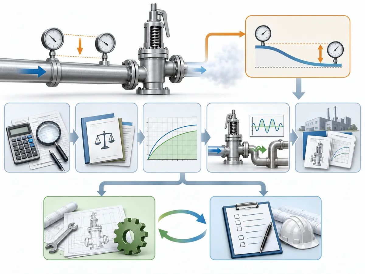
An exceedance should therefore lead to verify → classify → assess → redesign if necessary, rather than “3.1% → automatic failure” or “engineering analysis → automatic acceptance.”
What to Document for Engineering Review or RFQ
An engineer or valve supplier cannot evaluate an inlet-pressure-loss concern reliably from valve size and set pressure alone.
The review package should describe the protected system and the calculation that produced the concern.
| Information to provide | Why it affects the inlet-loss review |
|---|---|
| Protected equipment / pressure boundary | Defines where the inlet path begins |
| Governing code, standard, and project specification | Determines the applicable assessment basis |
| Credible relief scenario | Defines the duty being reviewed |
| 整定压力基准 | Required to interpret percentage-based criteria |
| Required relieving rate | Defines the required protection duty |
| Flow rate used in the inlet-loss calculation | Reveals whether the hydraulic basis matches the selected method |
| Fluid and relieving phase | Affects hydraulics and standards scope |
| Inlet piping layout / isometric | Shows line length, elevation, routing, and restrictions |
| Pipe sizes, reducers, fittings, and valves | Establish the sources of nonrecoverable loss |
| Rupture disk or other upstream device, if present | May add hydraulic resistance |
| Calculated inlet pressure loss and calculation method | Shows the result and how it was obtained |
| Relief-valve architecture | Affects the applicable stability or analysis route |
| Pilot sensing arrangement, where applicable | Can change how protected-system pressure is sensed |
| Device-specific operating data required by the selected analysis | Prevents generic assumptions about actual valve behavior |
| Lift, inspection, and repair history for an existing installation | May reveal evidence relevant to stability assessment |
This is also where general technical guidance ends and product-specific evidence begins.
A public article can explain the inlet-loss decision process. It cannot establish the dynamic behavior, remote-sensing arrangement, stability limit, allowable inlet pressure loss, or advanced-analysis data for a specific safety valve model unless those facts are documented for that model.
So a supplier inquiry should not stop at: “Can your valve work with more than 3% inlet pressure drop?”
A technically useful inquiry provides the relief duty, applicable standard, hydraulic calculation, valve configuration, and unresolved engineering question.